
|

|
Forum Index : Electronics : 8 KW Inverter Build
| Author | Message | ||||
VK6MRG Guru Joined: 08/06/2011 Location: AustraliaPosts: 347 |
LOL.... This is gold! Anyone remember the TV show on the ABC called Monkey? This TV show was based on this Chinese novel. Watched every episode as a kid growing up. Good times. Its easier to ask forgiveness than to seek permission! ............VK6MRG.............VK3MGR............ |
||||
| stevebequik Newbie Joined: 20/07/2016 Location: AustraliaPosts: 12 |
Hey Madness My build I also will be mounting the fets underside. Fets are TO-247 IRFP4332 I also want to reduce the mainboard down to 100mm wide so I can fit 2 prototypes on a 200mm x 300mm sheet. Any chance you can post your artwork. Thanks |
||||
Madness Guru Joined: 08/10/2011 Location: AustraliaPosts: 2498 |
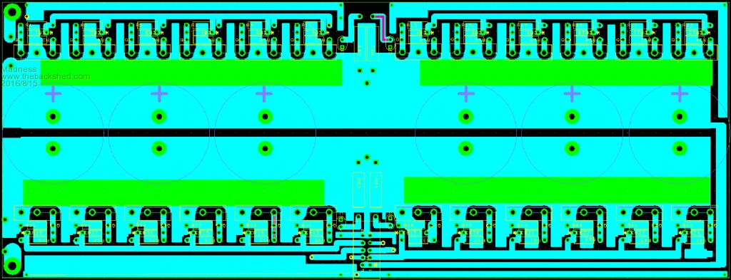
Hi Steve, Yes, no problem, I have yet to verify it is working correctly but I believe it is right. I am using 250 wide PCB so I have made it fit on the size and is 100 mm wide, the image below are from Design Spark, can send you the files if that is any help. 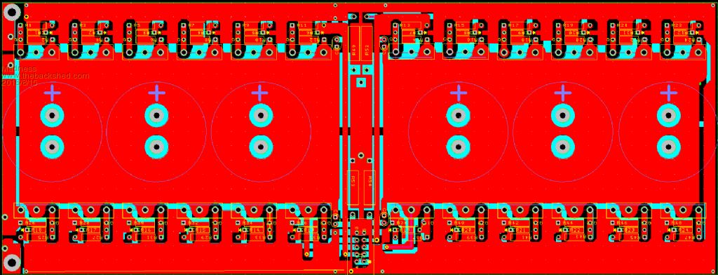
There are only 10 types of people in the world: those who understand binary, and those who don't. |
||||
Madness Guru Joined: 08/10/2011 Location: AustraliaPosts: 2498 |
Finally, I have made some progress after much tearing out of hair, exploding MOSFETs and not to mention swearing and kicking the cat(don't have a cat so don't worry). I have got a working Inverter, had some (understatement) help from Oztules (Dr Nefario) to nut it out. John tries to pass himself off as the village idiot but he is way too modest and smart to be anything remotely close to being an idiot. The voltage feedback to the control PCB must come directly from the output of the transformer, not after the filter or anywhere else! If you don't want to destroy MOSFETs by the bag full keep this in mind. So now I have my Inverter running in pieces on the bench, had it running the 2400 watt heater in my hot water today for 30 plus minutes and everything got just warm to the touch. After all the dramas I had with this I have made a PCB very similar to the original PJ design but condensed down slightly to fit on the 250 X 150 MM 2OZ PCB blanks I have. I will post some photo's tomorrow, all going well should get it in its case then. There are only 10 types of people in the world: those who understand binary, and those who don't. |
||||
Grogster Admin Group Joined: 31/12/2012 Location: New ZealandPosts: 9308 |
WHY does having the VFB AFTER the filter, cause MOSFET death? I will make sure I put my VFB transformer directly on the toroid output, but why does having the VFB transformer past the inductor etc cause the FET's to die? That point in the supply is the actual output you are using, so seems logical to tap into it there.  Smoke makes things work. When the smoke gets out, it stops! |
||||
Madness Guru Joined: 08/10/2011 Location: AustraliaPosts: 2498 |
Yes I hear what you are saying and it seems to make sense, but I have proven what I have written above to be correct, ignore it at your own peril!  Also, I forgot to add that getting the VFB wrong will take out the MOSFET driver chips also, so make sure you have some spares of those on hand if you want to experiment. Having it wrong does work with an EI transformer, but literally lasts 500 milliseconds on a Toroid. There are only 10 types of people in the world: those who understand binary, and those who don't. |
||||
Grogster Admin Group Joined: 31/12/2012 Location: New ZealandPosts: 9308 |
No, I won't - I will certainly do what you are doing. Thanks for your post, and linking me here from my other thread. There are SO MANY threads on a few forums now about these inverter builds, and trying to remember all the important bits from each one....   My current feedback board takes the VFB from AFTER the filter and the C/T, so I am very glad I read the above - I still have time now, to change the FB board, so that the VFB transformer is connected directly to the toroid output. Smoke makes things work. When the smoke gets out, it stops! |
||||
oztules Guru Joined: 26/07/2007 Location: AustraliaPosts: 1686 |
The filtered output is a consequence of what happens in the VFB loop.... not a consequence of the result of the loop. By using the final filtered output for the VFB, you are not feeding back what happened in real time in the loop, but in fact feeding back a result that has been massaged outside the working loop... a kind of hysteresis loop... that wont work properly. Why....because the information is polluted.... and does no longer contain enough information of what has happened in the loop.... coz you filtered the salient info out. To have high speed load levelling.. ie no sag if you dump 3kw on it and take it off, you need to sample in real time at the coal face with what actually happens in the transformer.... otherwise you cant make up the scaling fast enough to correct it properly... so it will overshoot high and low very fast with the wrong information to make it right... see tinkers traces. That shows the indecisive wave form before the filter ( total mess of noise over a sine wave), and the filtered output... a rough approximation of a wave... add load, and it all goes bang, as the wrong decisions actually count. Mad had the same sort of thing, but it was near instant death. not sure why tinker had time to measure his, must have been some slack in there somewhere... maybe the longer legs of the fets helped... or the 002 board is slightly different in the processing of the signal.... but the end result is always the same.... magic smoke released. ..........oztules Village idiot...or... just another hack out of his depth |
||||
Grogster Admin Group Joined: 31/12/2012 Location: New ZealandPosts: 9308 |
Excellent description of events - thanks. I understand completely why that happens and why it needs to be on the toroid now. I will make 100% sure I put my VFB transformer DIRECTLY on the toroid output - before the inductor and 1uF filter caps. Smoke makes things work. When the smoke gets out, it stops! |
||||
| Tinker Guru Joined: 07/11/2007 Location: AustraliaPosts: 1904 |
Yes, that "read carefully" statement above also applied to my magic smoke experiment. Having it taken apart by now showed all but two mosfets blown, some to smitherines. I'm in the process of a complete rebuilt, this time with 6 mosfets per bridge leg. Why my original set up only blew after a load was applied, it actually ran for some time while I took pictures of the unloaded CRO trace, might remain a mystery as I will not repeat that exercise  . .But the trace pic does show the mains (LC) filter is doing something  . But I will try it first without that filter, taking oztules advice. . But I will try it first without that filter, taking oztules advice.Just to reiterate, where exactly is the 2-4uF cap located in that loop? Is it secondary - current C/T - VFB transformer - 2.2uF cap - mains filter & voltage/power measurement - output? or secondary - 2.2uF cap - current C/T - VFB transformer - another 1uF cap - mains filter & voltage/power measurement - output, as I had planned? This time I'd prefer do connect it right  Klaus |
||||
Madness Guru Joined: 08/10/2011 Location: AustraliaPosts: 2498 |
Might be something else that gets released with those big bangs also, pays to have spare underwear on hand. There are only 10 types of people in the world: those who understand binary, and those who don't. |
||||
oztules Guru Joined: 26/07/2007 Location: AustraliaPosts: 1686 |
The VFB transformer and the 2-5uf shaping cap share the output terminals of the secondary directly... can be some distance away, but they see the secondary warts and all... then anything you want after that. The sine wave at that point will be near perfect, but at high resolution, will have the staircase of the 20khz impressed in it very finely.... then you can filter that out next. Then you will see how the filter works, so far it is the low frequency scramble we have seen it screen out,..... how it reacts to 20khz will remain to be seen... hopeful, but uncertain. ..........oztules Village idiot...or... just another hack out of his depth |
||||
Grogster Admin Group Joined: 31/12/2012 Location: New ZealandPosts: 9308 |
So is this the correct arrangement: 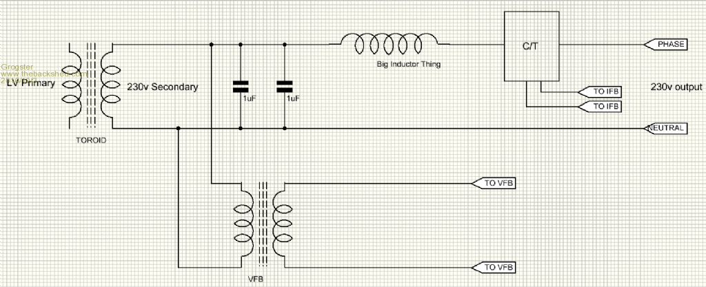 ...or this: 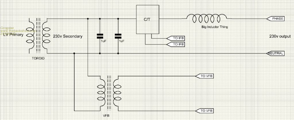 Smoke makes things work. When the smoke gets out, it stops! |
||||
| Tinker Guru Joined: 07/11/2007 Location: AustraliaPosts: 1904 |
Mine is gonna be the second drawing (...or this:) as the VFB transformer, C/T core and shaping caps are all on the same little PCB. I will connect the "big inductor thing" (mine also has small caps on it) last in the queue, just before the mains connections to my house. Oztules, I'll keep my fingers crossed for that big inductor filter to attenuate the 20KHz noise too. Thanks for pointing my nose in the right direction for looking at the CRO screen. Klaus |
||||
oztules Guru Joined: 26/07/2007 Location: AustraliaPosts: 1686 |
No 2 looks good. ......oztules Village idiot...or... just another hack out of his depth |
||||
Grogster Admin Group Joined: 31/12/2012 Location: New ZealandPosts: 9308 |
Cool, thanks. Smoke makes things work. When the smoke gets out, it stops! |
||||
oztules Guru Joined: 26/07/2007 Location: AustraliaPosts: 1686 |
Just when you think you've nailed it, something else proves you wrong... this seems to be normal for me... The position of the filter made a singularly impressive improvement for Mad, and after we worked out why this may be,,, I find that in one of my big units ( the one that has been on test for the last few weeks driving the house 24/7... has the filter before the VFB transformer.. contrary to what was known to work... but there it was.... working... yes it sees 5kw every day and sometimes 7kw for 5 mins or so.... so it works, but I don't know why. It only has the aerosharp 3kw filter in it (x2 parallel). So we know some installations suffer if the filter is placed wrong,and all my other ones are in the supposedly right place and work fine but this one runs perfectly fine too.... why .... don't know.... run clean out of ideas..... So Tinker, check everything as well as changing the filter position... something else is/maybe in play here, and not sure what it can be. Sometimes it just works....  and sometimes we don't know why..... and sometimes we don't know why.....  ...........oztules Village idiot...or... just another hack out of his depth |
||||
Grogster Admin Group Joined: 31/12/2012 Location: New ZealandPosts: 9308 |
I think this sums up my feelings on some of these points now..... https://www.youtube.com/watch?v=umDr0mPuyQc Smoke makes things work. When the smoke gets out, it stops! |
||||
Madness Guru Joined: 08/10/2011 Location: AustraliaPosts: 2498 |
After many trials and tribulations, I am close to getting a working inverter. Somewhere I got the wrong information for the snubbers, they need to be 103 3KV caps and 2W 47-ohm resistors. Also after trying several different circuit board layouts I have now made a design that is very close the original Chinese design. This also uses the heatsinks as conductors for the positive input and AC output. I am yet to test this layout but received an order of MOSFETs I was waiting on today. Here is how I have made the case, very similar to Oztules with 2 Aero-Sharp cases bolted together, except I have included a twist. That is I have rotated it 90 degrees so the air can flow better with natural convection as well as with the assistance of 4 140mm fans. 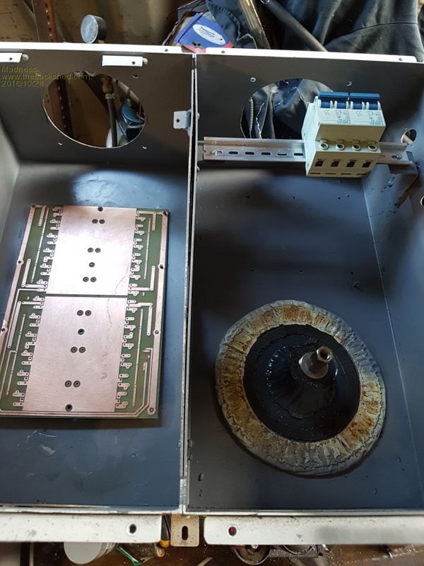 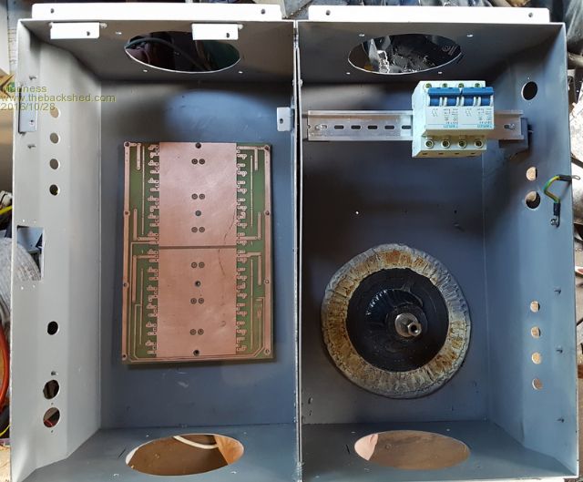 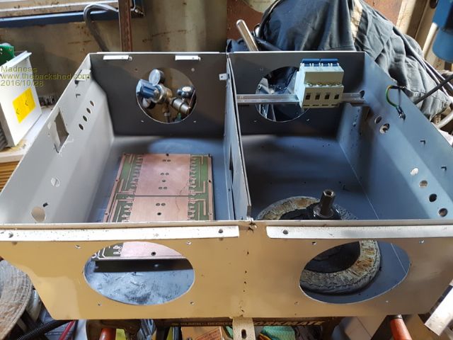 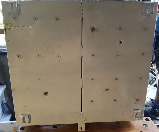 There are only 10 types of people in the world: those who understand binary, and those who don't. |
||||
| Tinker Guru Joined: 07/11/2007 Location: AustraliaPosts: 1904 |
Cutting those big fan holes in 2mm ss would not be my idea of fun  , good on yer for giving it a go. , good on yer for giving it a go.Your comment about 3KV snubber capacitors has me wondering, that rating is more often found in high voltage inverters. I'm using mains rated mylar capacitors which I hope is ample in a 60V primary circuit. Klaus |
||||