
|

|
Forum Index : Electronics : Building a new Inverter.
| Author | Message | ||||
oztules Guru Joined: 26/07/2007 Location: AustraliaPosts: 1686 |
Transformers can take terrible abuse for short periods generally. Heavy load and short circuits do NOT saturate cores, only voltage and frequency can affect that. So how much can it take?? This is really up to you. It can take many many kw for short duration, and less kw for longer duration. The core won't care once it is designed to not be in saturation, so the only thing left to consider is the copper losses in these extreme conditions, and the voltage sag you can tolerate. Copper loss is a function of the resistance.... so more copper is good, and with the torroid, sag is also limited really by the copper losses as well. So if you were to wind the next 85 turns three in hand, you would have a very powerful unit... and 6kw would not be too much problem for intermediate periods. 3kw for longer duration. Off grid you are unlikely to have those powers for long durations, as your batteries will be unhappy. In short, three in hand 85t to finish the secondary will run a house. Another thing to consider before you try to run the bare minimum. The PJ only has current regulation from looking at the AC output with the CT near the AC I/O terminals. So if the voltage sags, the cpu will drive up the pulse width to compensate... if the voltage is still sagging it will push it up further.. it has no cycle by cycle limiting.. so it is possible to o/load the output fets by having too light a secondary or primary, getting rotten regulation, and causing it to blow up at high power. If you keep the copper losses very low, this cannot happen easily, so you will be able to endure much higher outputs for longer if you keep R low.... the magnetic circuits are very tight in torroids. We need to worry about this, not so much for blowing up, but for heating the fet heat sinks too fast. A lossy transformer will work the fets much harder for the same power than a tight transformer..... and you will likely trigger a heat o/l event more than anything else more dramatic. The tight torroid makes it near impossible to use the auto UPS function of the inverter for battery charging. If you want to charge with it..... turn it off, connect ac then turn on.... and most importantly,you MUST MUST turn off the unit before disconnecting the AC source, or the inverter will instantly go back to 50.0 hz, from whatever the mains was, and likely blow everything up due to the inrush currents to the torroid.... up to 60 times the run currents. If this happens to coincide with zero crossing .... it will be toast. If it happens at the AC peak, there will be no problems. Likewise, to test the transformer on the mains you will need a current limiter somewhere in the ac line, as unless you connect up at exactly max AC waveform, it will blow your biggest house fuse in the blink of an eye. zero crossing is the worst point for this, not Ac max. ...........oztules Village idiot...or... just another hack out of his depth |
||||
| gpalterpower Senior Member Joined: 19/07/2009 Location: AustraliaPosts: 175 |
Thanks Oztules. And thanks for you informative reply. I was calling you Oz before ( for short). I tend to do that, so my apologies. 
I can do the additional 3 in hand 85 turns of 1.9, but just a question before I start. I was unraveling the mylar insulation last night to see how it was wound underneath ..... 4 layers of tape later I came down to the 3 in hand start and finish, which I found out is all wound individually, with a separate layer of insulation between each wind...different to what I first thought! It was easy to distinguish and count the EXACT turns. There is 98 per wind. 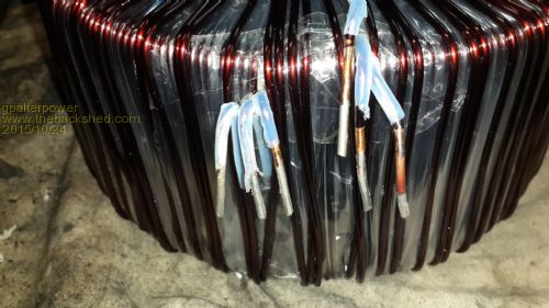
Now that I know this, it would be less work to wind just one extra layer 98 turns of 2.25 and parallel that with the third in hand, then, series with the remainng 2 in hand. BUT, would it be sufficient to do the same job and still power the house?? Would it be down in output, as compared to what you suggested as winding the 85 turns 3 in hand and adding them in series. If that sounds confusing...it is to me!  . .
Dont want to go beyond what you are suggesting. I appreciate you time in this matter, but it could save me some time winding.. I would end up with 196 turns of 8mm squared, slightly less as compared to a combination of 98 turns of 12mm2 and 85 turns of 9mm2. Plus it would give me additional room for the primary. Which seems to be an issue 
Thanks also for you advice on the charging batteries thru the inverter. With enough panels, hopefully, I wont be needing to go down that track, but now at least I am aware of what could happen if I do. Could be catastrophic!! Marcus if it aint broke dont fix it!! |
||||
oztules Guru Joined: 26/07/2007 Location: AustraliaPosts: 1686 |
Something not quite adding up here. If the inner windings are 98 turns then their voltage according to your testing is 98 x 1.4v or 137v So if we use two of these as the first half of our winding we have 137v. If we then use the extra winding, and series it with those, we get 137v + 137v or 270 odd volts. We then wind another 98 turns and parallel that with the second half, we finally get 196 turns 2 in hand@ 270v.... total. Thats fine, and will carry good current. It is actually a better transformer for idle losses, and that means 198/16=12 turns for the primary for 24v system. So yes you only have one winding to put on there..... 98 turns of 2.5mm wire. Does that verify your thoughts? Oz is fine too. Make sure that you verify each winding voltage wise before you tie them together.... One turn makes a huge difference if incorrect on a big torroid.... 1.4v at what current...... ............oztules Village idiot...or... just another hack out of his depth |
||||
| gpalterpower Senior Member Joined: 19/07/2009 Location: AustraliaPosts: 175 |
Thanks Oz. Well, mes thinks eyes better go back and recount dems windins agin!! Maybe I accidentally counted a turn or 2 from another wind. Any way it seems to be an easier way to achieve a similar outcome, and like you say it will be a better tranny for idle losses. And yes, it does verify my thoughts. All I need to do now is procure some enameled wire so I can get onto the rewinding stage. I do realise that is very important to make sure that I wind on exactly the same number of turns. Ill look more into that. Thank you for you help. Much appreciated . Marcus if it aint broke dont fix it!! |
||||
| Pete Locke Senior Member Joined: 26/06/2013 Location: New ZealandPosts: 181 |
...Go see a motor rewinder. Big places like that have left over bits of drums of all calibre of wire. Free if asked the right way  . Yes, been there, done that with rewinding the 1965 V.W Kombi generator. Good luck . Yes, been there, done that with rewinding the 1965 V.W Kombi generator. Good luck  |
||||
| M Del Senior Member Joined: 09/04/2012 Location: AustraliaPosts: 155 |
Seeing as the requirements for reducing idle draws and wasted power is something that can be achieved by a handy man with some electrical skills, a toroid, some wire and a bunch of connectors, is the only reason commercial inverters are lousy in this regard simply cost, or is there another reason behind it. This is something I want to do when physically able to in the near future. I have most of the required abilities and can draw on the expertise of the elecos at work for aspects I am unsure of. Mark |
||||
| Gizmo Admin Group Joined: 05/06/2004 Location: AustraliaPosts: 5078 |
Its all about cost M Del. Cheap inverters use cheap transformers, you get what you pay for. Toroids cost money, so you wont see them in cheap inverters. High end inverters like the Latronics brand, do use toroids, and therefore have low idle current and great efficiency, but you have to pay many thousands of dollars for a Latronics. Glenn The best time to plant a tree was twenty years ago, the second best time is right now. JAQ |
||||
| M Del Senior Member Joined: 09/04/2012 Location: AustraliaPosts: 155 |
Figured it was cost, unit went through a bunch of cheap inverters some years back when gensets became rare for a while, mounted in the back of maintenance vehicles drawing from 24v batteries. One hand lift for 3kw units about the size of an encyclopaedia  , unlike some 2kw units that were two handed and bulky. Cost won out and they kept using the cheapies. , unlike some 2kw units that were two handed and bulky. Cost won out and they kept using the cheapies.
My grid connect is large and heavy, about 96% efficient and has a toroid. It has lasted well unlike some purely electronic ones I have seen. Gets nowhere near as hot as them either. Mark |
||||
| Clockmanfr Guru Joined: 23/10/2015 Location: FrancePosts: 429 |
What I discovered with Oz's Inverter toroid construction was the true simplicity of oztules design. By stacking two or even 3 cores together the centre hole becomes to narrow for a standard toroid machine winder to get in. I purchased 2 cores with each at 190mm OD x 90mm ID X 60mm thick, 6kgs 1.8mm diameter copper winding wire, and some 6 meters of 50mm/2 single covered wire. Total cost for my Oz toroid was about £260 GBP. I put 4 separate 1.8mm diameter 118 turns secondary on my cores and 14 turns of the 50mm/2 for the primary. Total cost for my 'OzInverter' was about £500 GBP. Next time I will go for the bigger cores with a larger OD and a bigger hole in the middle as I struggled to get 14 turns through in a tidy manner. And I will take the primary to 75mm/2 thick...... These are ideal,... 2 off these..... http://www.airlinktransformers.com/toroidal_cores/ros217/ The Metal enclosure is 600mm high, 400mm wide and 300mm deep. I need a support bracket as the whole weighs 52Kgs..... 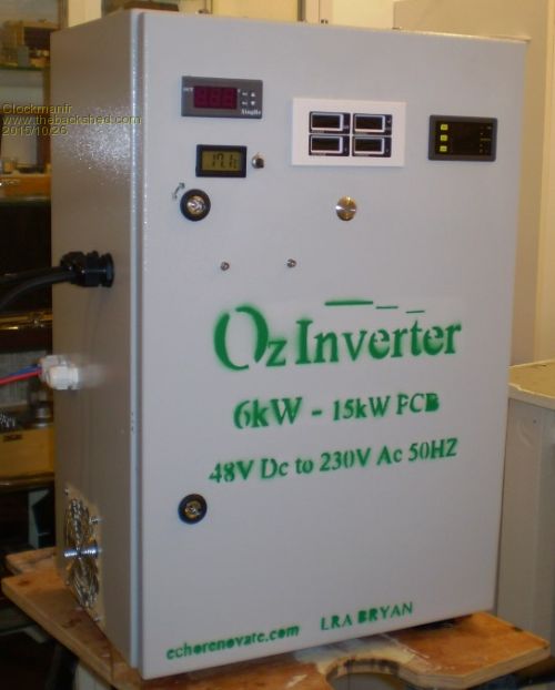
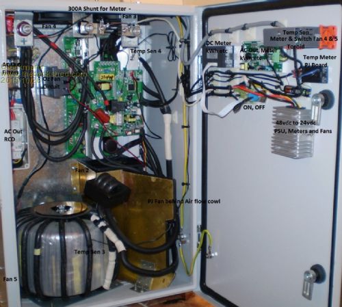
Everything is possible, just give me time. 3 HughP's 3.7m Wind T's (14 years). 5kW PV on 3 Trackers, (10 yrs). 21kW PV AC coupled SH GTI's. OzInverter created Grid. 1300ah 48v. |
||||
| gpalterpower Senior Member Joined: 19/07/2009 Location: AustraliaPosts: 175 |
Thanks Pete, I visited the local motor rewinder this morning . I know these guys preety well as I purchase enaleled wire from them for my work. They have lots of wire sizes but not the one I need. 2.25 is an in between size for them. They have lots of sizes up to 1.7 then a gap till 2.8mm. Im probably going to wind 2 in hand of 1.6mm. We just got back from NZ yesterday after a short 4 days in Queenstown and Glenorchy. Absolutely beautiful. Where you from? Nice job on the cabinet inverter clockmanfr ok ...................to the workshop. Have a big job ahead of me today  if it aint broke dont fix it!! |
||||
| gpalterpower Senior Member Joined: 19/07/2009 Location: AustraliaPosts: 175 |
Morning all Well, got straight in to it on Friday . I cut down a bobbin from an old wire reel into something that was just small enough to fit thru the centre hole, and, after a little maths, I wound what I thought was enough wire to complete the 96 turns of 1.6 wire in the lathe. Plus a little extra just in case! Better too long than 5 turns too short! 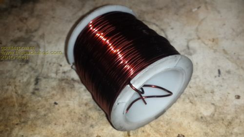
This definitely made things easier as I could pass the bobbin thru the hole and keep the wire taught at the same time. A glove helped as it was cutting in to my hand. First layer done and on to the second. Same again. Slow process but just keep at it 
I thought before doing the final connections, I had better test to make sure the new winding were the correct amount of turns. I did this by powering up any one of the 3 original windings thru a 60w lamp. In theory, the voltage that was induced in the new winding should be exactly the same as any of the other 3 original. When winding the 2 new 1.6mm wire I placed a few additional turns on each. Checking the voltage on the new winding was a couple of volts too high, so I just removed turn by turn until I had the EXACT voltage on each new wind as compared to the original. I paired off 2 of the three original windings as my start and the finish was connected in series, with the remaining third, in parallel with the 2 new I had just wound. I now had a single wind of approx. 190 odd turns of 8mm squared wire. 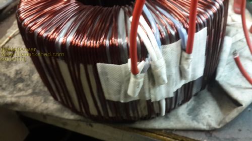
I placed 12v across the new winding and waited till it warmed up. It didn't take long as it was drawing 60A. I then poured varnish (isonel 31) over the windings and watched it melt like hot butter on toast. Then let it air dry overnight. sticky stuff!! 
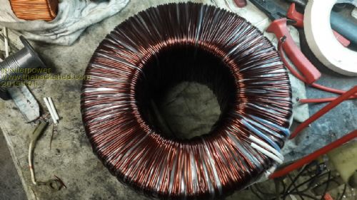
I saved all the mylar insulation( had what seemed like klms of it) and wound it on to another bobbin in the lathe. 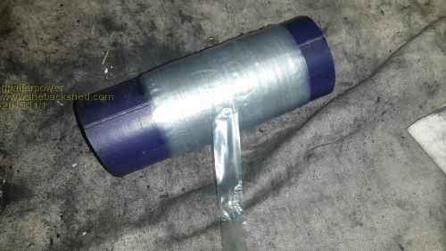
Same story again winding, winding and more winding, passing the bobbin thru the hole till I achieved my goal of insulating the core. Back in the oven again to set the varnish. Solid as! Winding are tight and the mylar seems to be a heat shrink material looking even tighter! Finished product....for now anyway. primary next 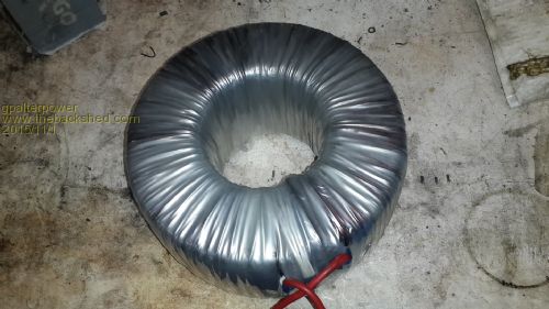
Marcus if it aint broke dont fix it!! |
||||
| gpalterpower Senior Member Joined: 19/07/2009 Location: AustraliaPosts: 175 |
PS Pete, congrats on the all blacks . Well deserved win.  if it aint broke dont fix it!! |
||||
| Pete Locke Senior Member Joined: 26/06/2013 Location: New ZealandPosts: 181 |
Thanks Marcus. Made it to the T.V for the game early. Cracker of a game  . .
Glad you enjoyed your trip to N.Z. Very nice area you visited. I'm up a bit higher and on the other side of the South Island in a town called Hokitika. Best place in the world...although I might be a bit biased to that statement 
Cheers Pete. P.S Great looking toroid you have created. Great stuff. |
||||
| Tinker Guru Joined: 07/11/2007 Location: AustraliaPosts: 1904 |
Marcus, using a trimmed down bobbin to wind wire through a toroid core is not the way I would do that. I'd use a shuttle (as in weaving loom), this can simply be cut from a plywood strip and made as long as is comfortable to use. Of course, the longer it is the more wire it will hold for the same full shuttle diameter. Klaus |
||||
oztules Guru Joined: 26/07/2007 Location: AustraliaPosts: 1686 |
Klaus, That only works well with thin wire... it is next to useless for heavy gauges... you end up with a sloppy kinked mess in no time. Using the method Marcus used, provided you unwind in the right direction, the heavy wire will lay tightly against the torroid walls, without kinks or bends. The shuttle method relies on you being able to straighten the wire out each pass through by just pulling it tight... you need about 100kg to pull straighten 2mm wire, particularly if it is work hardened. 1.6mm is too strong to do that way either.... particularly a rewind.. the wire gets very springy .. quickly. I have wound quite a few now, both 1.6mm and 2mm.... shuttle method sounds good until you try it with heavy wire. Dual and tripple torroids is even more problematic, as the internal straights are 5 or 6 inches long or more, you need the wire to naturally hug the wall, or it becomes a springy mess. Been there and tried it. http://www.anotherpower.com/board/index.php/topic,1044.0.html ................oztules Village idiot...or... just another hack out of his depth |
||||
| Tinker Guru Joined: 07/11/2007 Location: AustraliaPosts: 1904 |
Thanks Oztules, point taken. A very long time ago, when I was an apprentice one job was to wind current transformers which had an elongated toroid core (to pass heavy busbars through) and they used fairly thick wire, wound on with a bobbin. But the core was only about 50mm high, I see your point about kinks in longer cores so I won't try that method should I ever locate a suitable junked inverter for doing your modifications. Still looking... Klaus |
||||
| Gizmo Admin Group Joined: 05/06/2004 Location: AustraliaPosts: 5078 |
Just a update on my inverter. Its been in constant use for a couple of weeks now, and has worked perfectly. The variable speed cooling fan has worked well, I can hear it speed up and slow down as loads cut in and out. On cool nights it stops altogether. Occasionally I get a alarm beep and LED flash when I start up a big old bench disc sander. The sander uses a old school induction motor with the internal centrifugal contacts, and a big flywheel. Welding is fine on my small old mig welder, and no issues with any other power tools. The icing on the cake has been the stormy weather. Last week most nights we had storms with lots of lightning, and for the first time in years I didn't care. Usually as a storm approaches I would shut down the inverter to protect it, and read a book under a 12v LED light for a couple of hours. But now I can leave the inverter running and watch TV, knowing if a nasty lightning strike takes out the inverter, I can switch over to the other inverter, and probably fix the damaged one myself. Glenn The best time to plant a tree was twenty years ago, the second best time is right now. JAQ |
||||
| gpalterpower Senior Member Joined: 19/07/2009 Location: AustraliaPosts: 175 |
Pete. Yep. Thought the all Blacks would win. You guys are just too good. But then, rugby is like a religion in NZ. Klaus. I was originally thinking about using a shuttle as you suggested, but I knew just how stiff that wire can be. Anything over 1.25mm starts to get a little cantankerous. I wound hundred's of armatures, rotors and stators off vehicles over the last 30 years. Was part of my apprenticeship back in the day . Nothing wasted. ...not like today. ..just get a new one! ! Oz, thanks for your help. Priceless! I'm at the point where I wind on the primary. Was wondering if I could get away with using 35mm cable. Have a whole role of it here. Multi strand. Nice and flexy! Glenn, good to hear your new inverter is working fine and that you don't have to read by a backup led lamp when a storm approaches. Speaking of storms we have had a couple of beauties the last few nights. Look like tonight will be fine. Had some good rain! Marcus. if it aint broke dont fix it!! |
||||
oztules Guru Joined: 26/07/2007 Location: AustraliaPosts: 1686 |
Yes you can use 35mmsq, but for 24v you will be using it fairly hard all the time.... prefer if you can get 2 in hand in there... 5kw=200 amps@ 24v..... so your over the limit up there really for any extended period. ok for 48v... but at 24, stay below 3kw most of the time.. or better still attach a $2 digital thermometer to the tranny and see how much you can drive it with before it starts to get warmer than you want. Having said that, providing we don't clip ( from sagging voltage) , the only real limit with the transformer is temp. ............oztules Village idiot...or... just another hack out of his depth |
||||
| mason Regular Member Joined: 07/11/2015 Location: CanadaPosts: 86 |
Hi all, just wondering if anyone could give me the specs for the pj main fan? thanks Billy |
||||