
|

|
Forum Index : Windmills : VAWT, F&P, analog MPPT project
| Author | Message | ||||
| govertical Guru Joined: 11/12/2008 Location: United StatesPosts: 383 |
http://www.thebackshed.com/windmill/FPRewire.asp Hi, connected the coils to form two 6 per phase three phase star. I connected them in parallel, center to center and output to output. With no load the PMA spins with no gogging, there is some drag. When I connect the PMA to a load there is a lot of cogging and I can not measure any voltge at the output. I noticed on the reference page that there are two diagrams one showing the centers connected and one showing no connection of the centers. Is there a reason for this? just because your a GURU or forum administer does not mean your always correct :) |
||||
| govertical Guru Joined: 11/12/2008 Location: United StatesPosts: 383 |
Hi,I was able to fix the problem and I made a quick manual test of the modified F&P. Lower voltage with more current at the input. Should be a better match for buck converter project I am working on. The input voltage should not exceed the circuit voltage max limit. 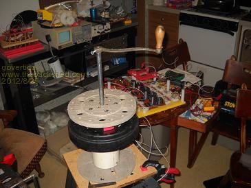
just because your a GURU or forum administer does not mean your always correct :) |
||||
| govertical Guru Joined: 11/12/2008 Location: United StatesPosts: 383 |
http://www.circuitstoday.com/scr-applications Greetings, I have found a possible solution for the over voltage protection circuit. The circuit located at number 4 uses the AC to trigger the circuit. I could duplicate the circuit 3 times, one for each phase. When the SCR’s are triggered the added resistive load would brake the turbine to lower the input AC voltage and the buck converter would continue to lower the voltage at the input capacitor of the buck converter on the DC side. I am not sure of the values required. D5 could be two 200 volt zeners in series for a 400 volt trigger. Comments welcome. 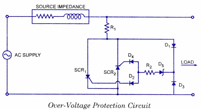 just because your a GURU or forum administer does not mean your always correct :) |
||||
| govertical Guru Joined: 11/12/2008 Location: United StatesPosts: 383 |
Hi, If I can get circuit working for single phase AC, this maybe a possible solution for a 3 phase configuration. Comments welcome. just because your a GURU or forum administer does not mean your always correct :) |
||||
| govertical Guru Joined: 11/12/2008 Location: United StatesPosts: 383 |
Hi, I tried to test the modified F&P with the OVP circuit. Because I modified the F&P stator I could not charge a capacitor to 400 volts to test to see if the OVP would trigger. I do have my moments. RPM was about 600 and max voltage at the capacitor was about 350 volts with no load. Even if I add a 1:7 belt drive to the modified F&P I should be safe to road test with the buck converters. I removed one of zener diodes from the OVP test causing the trigger voltage to be 200 volts. The OVP circuit triggered at about 200 volts and as I increased the RPM’s the voltage at the capacitor remained at 210 volts. The load resistor was only rated at 1 watt and became very hot but the circuit still functions. I have to increase the wattage rating of the load resistor. It looks like the circuit will work for my application, if used with a wind turbine and the buck converters, the turbine will brake because a resistive load is added when the OVP is triggered and the input voltage at the input of the buck converters will remain at a save value at higher RPM’s. 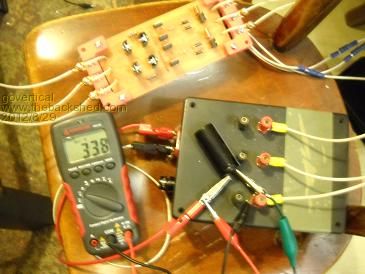
just because your a GURU or forum administer does not mean your always correct :) |
||||
| govertical Guru Joined: 11/12/2008 Location: United StatesPosts: 383 |
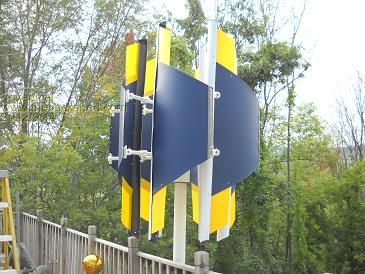
Hi, this is the style blade I can fabricate. The C shape will have end caps. The big question is what style will have better performance at average wind speeds? Please cast your vote, A, B, or C. It is a election year. 
just because your a GURU or forum administer does not mean your always correct :) |
||||
| govertical Guru Joined: 11/12/2008 Location: United StatesPosts: 383 |
Hi, making progress. Yes you guessed correct, no wind. 3 more blade to go. http://www.youtube.com/watch?v=cwfujuhw9ZU&feature=youtu.be just because your a GURU or forum administer does not mean your always correct :) |
||||
| govertical Guru Joined: 11/12/2008 Location: United StatesPosts: 383 |
http://youtu.be/NJ9XS6IQKzc http://youtu.be/wfN7aOOSg3g 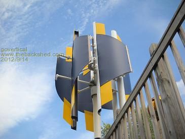
just because your a GURU or forum administer does not mean your always correct :) |
||||
| govertical Guru Joined: 11/12/2008 Location: United StatesPosts: 383 |
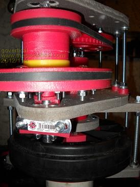
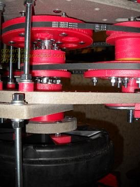
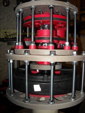
Hi, completely assembled F&P with belt drive. I counted the ratio and it is 1:4, I am going to tighten the belts and run it with the drill press for a few hours. I ordered a intronics solar MPPT25, it has a battery charging algorithm. The only problem is the max input voltage is 80 VDC. I will have to add a OVP circuit that will trigger just under 80 volts and configure the F&P as four 3phase with 3 coils per phase connected in parallel. I was communicating with one their engineers and he said it should not be a problem as long as the OVP triggers. I plan to continue working on my circuit. 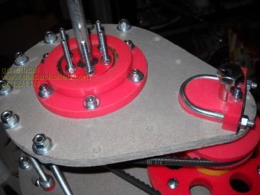
just because your a GURU or forum administer does not mean your always correct :) |
||||
| govertical Guru Joined: 11/12/2008 Location: United StatesPosts: 383 |
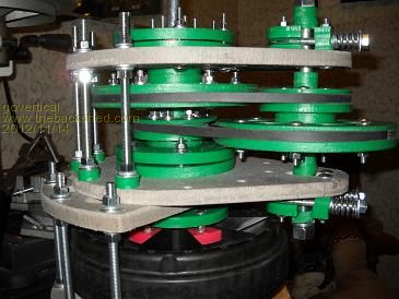
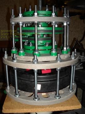
Hi, completed belt drive for F&P PMA. It would be nice to find a supplier for the pulleys. The pulleys are DIY V wall. The belt drive ratio is 1 to 4.25 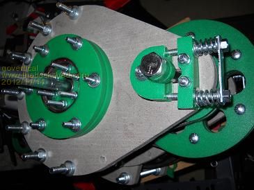
just because your a GURU or forum administer does not mean your always correct :) |
||||
| govertical Guru Joined: 11/12/2008 Location: United StatesPosts: 383 |
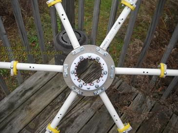
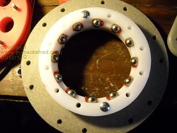
Hi, after observing the VAWT RPM and measuring the VOC in low wind conditions, I decided to mount a stock F&P stator on the 1 to 4 belt drive. I used a DIY 4 inch ID bearing so I could mount the PMA between the two blade rotors. Waiting for wind. 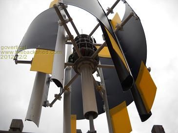
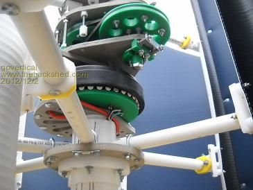
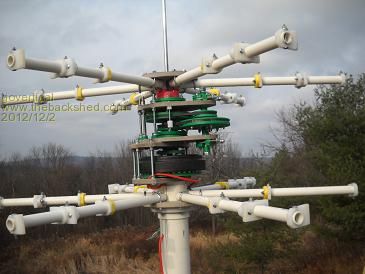
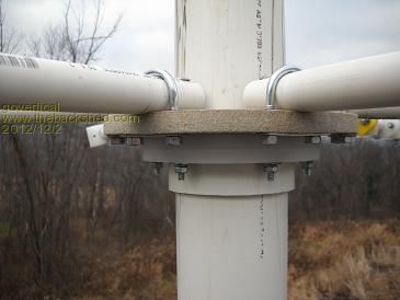
just because your a GURU or forum administer does not mean your always correct :) |
||||
| govertical Guru Joined: 11/12/2008 Location: United StatesPosts: 383 |
VAWT crash, RIP. 19 MPH wind speed, 3 amps @ 12 volts. Manual operation with hand crank, 5 amps @ 12 volts. Stock F&P with 1 to 2.5 belt drive transmission and MPPT data logger. Conclusion, even when testing the mast mount needs to be very secure. I need a faster blade design. Without the MPPT circuit output would be very, very low…. just because your a GURU or forum administer does not mean your always correct :) |
||||
| Warpspeed Guru Joined: 09/08/2007 Location: AustraliaPosts: 4406 |
Oh that is very bad after so much work. Perhaps electrically loading up the turbine to limit the voltage may not be the best approach with this. Braking the rotor electrically will massively increase the wind loading on the whole machine. Would it be possible to furl the blades by spilling air once the machine reaches some maximum speed and output voltage ? If the blades could close right up against each other, the wind would then effectively blow around a smooth cylinder with no turning at all. No need to go that far, but it should be possible to limit the maximum speed by controlling airflow. Perhaps some centrifugal weights and springs could be arranged to tilt the blades to reduce the open area caught by the wind on the up wind side. I would think the pitch of all the blades would need to be linked together, to prevent the whole thing wobbling or going out of aerodynamic balance, and to prevent cyclic blade flutter. Another way might be a small dc motor with a very large reduction gearbox to mechanically adjust the pitch of all the blades together. The output voltage could probably then be kept reasonably constant, or at least limited to some safe maximum. A small scale model may be a simple way of trying a few different ideas. Something you could hold outside the window of a car driven at various speeds. Cheers, Tony. |
||||
| govertical Guru Joined: 11/12/2008 Location: United StatesPosts: 383 |
hi, the MPPT brakes the turbine at 200 volts. The failure was cause by poor foundation construction. The turbine RPM never exceeded 60. Max wind speed recorded was 19 MPH. I should up and running in a few days. Thanks for the suggestions. just because your a GURU or forum administer does not mean your always correct :) |
||||
| govertical Guru Joined: 11/12/2008 Location: United StatesPosts: 383 |
Hi, I had some free time so I fixed the VAWT, strengthen the foundation, removed the springs from the belt drive to prevent the belt from jumping, and it is operational again. To cold to take to take pictures. After reviewing the test results, I am increasing the belt drive ratio a small amount. That should make the output about right for this size VAWT.  Waiting for wind….. Waiting for wind….. just because your a GURU or forum administer does not mean your always correct :) |
||||
fillm Guru Joined: 10/02/2007 Location: AustraliaPosts: 730 |
Curious to know, what is the right output for a VAWT of your size ? What do you caculate size on , is it blade surface area , then what surface area is your VAWT? |
||||
| govertical Guru Joined: 11/12/2008 Location: United StatesPosts: 383 |
Vawt power CalTec Study 10x Hi, I have been using the above calculator as a guide. 6’x4’ approximately 3 to 5 amps at 10 MPH. I think I should be getting twice the output. After reviewing my test results and finding the above study, my new approach for this project is to make multiple small low cost VAWTs and run them in parallel using a MPPT type circuit. Trying make one big VAWT no longer make any sense. It will take awhile to make more VAWTs and I will post results when available. just because your a GURU or forum administer does not mean your always correct :) |
||||
| govertical Guru Joined: 11/12/2008 Location: United StatesPosts: 383 |
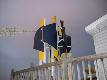
Hi, it is a learning project. I had springs on the pulley shaft, that was a bad idea, it allowed the belt to jump the cogs. I remover the springs. I am waiting for wind to see if the problem is fixed. It was working for a day and a half. I am hooked, if it takes another five years I will get the project working. I like Kinetic Art, 
just because your a GURU or forum administer does not mean your always correct :) |
||||
fillm Guru Joined: 10/02/2007 Location: AustraliaPosts: 730 |
Hi Vert, Well all good then if you are a total VAWT believer / builder / artist . The US VAWT output caculator, there is a foot note regarding alternator matching and this is more what I was trying to point out with the F&P , you need something with no iron drag/ cogging otherwise you will be looking at power under the 20%eff figures. Apart from that I did a comparison in surface are with my latest turbine that has a swept area of 10.17sq/mtr which is a 3.6mtr Dia Blade set , to get 10 sq/mtr with a VAWT it needs to be 5mtrs tall x 2mtrs wide, that then equates to 15.7 cubic mts or if you cut the cylinder and lay it flat is 31.4 sqmtrs of surface area, with the 40% finely tuned machine output figures are still under what my output figures, up to 35klm W/S @ 2kw when the furling starts to limit output. Basicly a VAWT needs to have 3 times more surface area to equal HAWT surface area output , which then also requires significant engineering with mounting such structures. The point is , it is very hard to get performance from a VAWT and is pretty well in the league of well funded organizations like Cal Tec etc , funny enough I have supplied them with GOE222 blades , where as a lot easier for the home builder with a HAWT to get meaningful output. Anyway , I like your work but still think if you put some time into knocking up some coil formers and slapping some magnets on a couple of steel plates you will be well rewarded with a alt that would not need gearing / belts and iorn losses. PhillM ...Oz Wind Engineering..Wind Turbine Kits 500W - 5000W ~ F&P Dual Kits ~ GOE222Blades- Voltage Control Parts ------- Tower kits |
||||
| govertical Guru Joined: 11/12/2008 Location: United StatesPosts: 383 |
Hi, I totally agree with you. One on one a HAWT wins hands down. I do not have the skills to fabricate a HAWT. I can fabricate a VAWT. I am using the F&P’s for experimentation. It dramatically illustrates the benefits of using a power conversion circuit like a MPPT circuit. Without a MPPT circuit the VAWT would not even spin at low wind speeds because most of power produced is lost as heat at the stator. A nice thing about the F&P is it is low cost and it is all ready fabricated. I removed the springs from the belt drive and I should have some wind today for testing, I will post results when available. After I finish the testing with the F&P I will try a axial flux, thanks for the suggestions. just because your a GURU or forum administer does not mean your always correct :) |
||||