
|

|
Forum Index : Windmills : Fisher & Paykel Micro Hydro
| Author | Message | ||||
| Dubyagee Newbie Joined: 15/06/2007 Location: United StatesPosts: 21 |
How about a solid wheel with drilled holes in the edge angled to receive the nozzles flow and angled drilled holes on the sides to redirect the flow back towards to nozzles somewhat. One piece would be a lot stronger but I dont know how efficient it would be. Probably did a horrible job of explaining it. Regards, Dubyagee |
||||
| Warpspeed Guru Joined: 09/08/2007 Location: AustraliaPosts: 4406 |
I assumed you were feeding three phases down three wires to your home, as that is the most efficient method of transmission, and measuring phase to phase, as there will be no neutral wire with this delta connection. If the three waveforms are perfectly sinusoidal (?), the peak of the phase to phase voltage reached, less about three percent will be the dc average coming out of a six diode bridge rectifier. I assumed 211 volts rms x 1.414 = 298.35v Less three percent = 289.4v Roughly 290v estimate The dc voltage coming out of the rectifier will not be perfectly smooth dc, but will have about a 6% ripple component, and the mean dc voltage you will measure about 3% less than the theoretical peak. If the waveforms are other than perfect sinusoids, (which is very likely), then the dc voltage you actually end up measuring could be slightly higher or lower than theory predicts. Cheers, Tony. |
||||
| Hydro John Newbie Joined: 31/10/2011 Location: United StatesPosts: 35 |
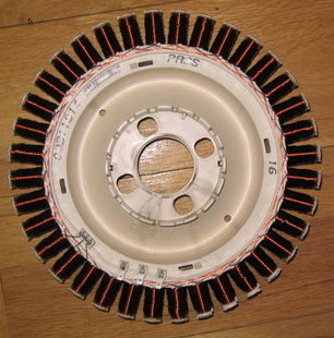
Hello Friends, [quote=Warpspeed]I assumed you were feeding three phases down three wires to your home, as that is the most efficient method of transmission, and measuring phase to phase, as there will be no neutral wire with this delta connection.[/quote] Just so I understand everything, I am sending a diagram of the way I have the wires connected to the 3 -40 watt bulbs. I think they are connected in Wye and not delta. I'm not sure if I have things hooked up right, but I think so. Also a picture of my unaltered 60 F&P rotor. There are 36 coils total with 12 in each phase. I think the 12 coils in each phase are connected in series and it looks like one terminal of each phase is connected to a common point and the other end of each phase exits the rotor to my house. Would this mean that the rotor is wired in Wye? The voltage reading I took was across 2 of the wires coming out of the rotor and not across the 40 watt bulbs. 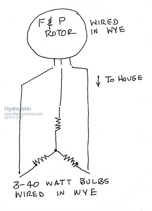
[quote=Dubyagee]How about a solid wheel with drilled holes in the edge angled to receive the nozzles flow and angled drilled holes on the sides to redirect the flow back towards to nozzles somewhat. One piece would be a lot stronger but I dont know how efficient it would be.[/quote] I'm not quite sure what you mean. Maybe you could post a diagram of your suggestion. I welcome any suggestions. Thanks John Hydro John |
||||
| Warpspeed Guru Joined: 09/08/2007 Location: AustraliaPosts: 4406 |
That is all exactly as I expected. The F&P must be connected in wye, to eliminate any circulating harmonic currents in the windings, car alternators are wired the exact same way, for the same reason. To turn the 211 volts phase to phase voltage into 290 volts dc, you require six diodes, assuming that is what you wish to do.  Cheers, Tony. |
||||
| Hydro John Newbie Joined: 31/10/2011 Location: United StatesPosts: 35 |
Hello Friends, Warpspeed: You are very impressive. It looks like I have 2 alternatives to get the power from the Turbine to the house. Either 3 phase AC, as others have suggested, or DC as you seem to prefer. Either way, once the power is rectified, I will need to get it to a voltage that is suitable for charging a 12 or 24 volt battery. How will I do this? Hydro John |
||||
| Warpspeed Guru Joined: 09/08/2007 Location: AustraliaPosts: 4406 |
I have been giving that some thought John. You could probably buy a commercial battery charger that used a switching power supply to convert 240 volts ac to properly charge your battery. The way these work, they rectify the ac mains voltage to create a high dc voltage, usually at around 340 volts (for 240v input). That dc voltage is then chopped at high frequency and fairly efficiently transformed down to the required lower voltage to charge the battery. The clever thing about that, would be that you could feed your 290 volts dc, or 350 volts dc, (or whatever you end up having) straight into the 240 volt ac input, and it would work perfectly. The actual input voltage of these switching supplies is non critical, because they are built to accommodate wide variations in mains supply voltage. An unmodified off the shelf unit should do the job admirably. If you want to run both hydo systems in direct parallel, you still can, and have the rectifier at the house. Or have two rectifiers and combine the outputs to feed high voltage dc to the house. Try it both ways, and see how it goes !!! There are advantages and disadvantages either way. Just did an ultra quick Google, a fully automatic 12v 20A battery charger, with fast charging, and float modes $70.00 on flea-bay. There are many comparable products flooding out of Asia that are of similar or identical design. http://www.ebay.com.au/itm/NEW-12V-Battery-Charger-20-Amp-Ca r-Boat-Caravan-/270784868768?pt=AU_Car_Parts_Accessories You can plug high voltage dc straight into the input of something like this, and it will not know the difference. The 12 volt side is completely isolated from the 300 volt side, so it will be as safe as if it was connected to the 240v mains. Cheers, Tony. |
||||
Madness Guru Joined: 08/10/2011 Location: AustraliaPosts: 2498 |
Are you sure an off the shelf charger will handle the frequency coming from the F&P alternator? There are only 10 types of people in the world: those who understand binary, and those who don't. |
||||
| Warpspeed Guru Joined: 09/08/2007 Location: AustraliaPosts: 4406 |
If you feed dc into the battery charger, the frequency coming out of the turbine before rectification is irrelevant. Cheers, Tony. |
||||
| Greenbelt Guru Joined: 11/01/2009 Location: United StatesPosts: 566 |
FROM PAGE 4, Posted: 14 December 2011 at 6:25am | IP Logged Report Post Quote Hydro John Hello Friends, Greenbelt wrote: The Jet stream from the Nozzle may need to be a bit lower down ( nearer to a tangent to the turbine cups) maybe down 3/8", I say this because I have read various documents about the design of Pelton wheels and the principal of energy transfer from water to wheel, Hydro John, Wrote; ( I have tried many different positions and the one pictured below seems to give the best results.) It is possibly causing some Drag when it is lowered because the splash water at 180 Deg. return may be hitting the Bucket behind it tending to slow it. Not Picking your work apart you are already showing positive results, just passing a few things on that I've picked up over a long time. This drawing will show how this problem was solved by others who Worked on these things. --------- Cheers, Roe Time has proven that I am blind to the Obvious, some of the above may be True? |
||||
| Don B Senior Member Joined: 27/09/2008 Location: AustraliaPosts: 190 |
Hi John, I had drafted a previous post for this thread but my wireless modem disconnected itself as I was trying to post it and it vanished. I fully endorse Warpspeed’s advice in his several recent posts. He really knows his onions. While my previous post suggested 3 switchmode chargers – one per phase, his is a far simpler solution to use one after the rectifier and hence fed with DC. With regard to where the rectifier should be, you will probably have the least losses if you run your power to the house as 3 phase ac. That being said, if you are using cores in a telephone cable for this; then the insulation is probably over stressed, and you will probably eventually get a cable fault. If you position the rectifier at the turbine, then you will only need a positive and a negative conductor, but voltage drop will be a greater concern. If you have enough cable on hand, then you could run a second conductor to your house, and use all of the wires in one cable as the positive, and all of the wires in the other as the negative. This would pretty much eliminate the voltage overstress problem. The second cable could be comprised of any odds and ends that you have, so long as its conductor cross section is at least the same as the total cross section of the wires in the existing cable. If you only have the existing cable, then use half of the total number of wires as the positive, and the other half as the negative. Regarding measuring the AC power, with your present lamp connection, the simplest way is to measure the voltage across one of the lamps (ie phase to the centre of the Wye), and the current going through that lamp, and your total Watts will be Volts by Amps by 3 (assuming that all of the lamps are the same size). Measuring the phase to phase voltage for this will not give the correct result. Concerning getting optimum performance from your Pelton wheel, remember that you will get maximum power when: • Your nozzle(s) give you the optimum combination of velocity and mass flow from the available head and supply capacity. • The fluid stream is turned through 180 degrees by each bucket. • The buckets move at half the nozzle velocity. • The fluid stream drops clear of the wheel with no remaining velocity, and does not interfere with the trajectory of any other buckets. This is obviously harder to arrange when the nozzle is directed at the top of the wheel. When you get an accurate power output measurement, you can calculate your present efficiency, but I imagine that there is still scope for improvement. Please keep posting your results. Regards Don B |
||||
| Hydro John Newbie Joined: 31/10/2011 Location: United StatesPosts: 35 |
Hello Friends, Thanks so much for all the good information and tips. My feeble brain cannot absorb it very quickly, so I am going to take some time researching and studying. In the mean time I am reworking my pelton wheel and will make some modifications to the shape of the spoons as Greenbelt and Don have suggested. Thanks John Hydro John |
||||
| BobMann Senior Member Joined: 30/06/2011 Location: United StatesPosts: 134 |
I had been toying with this ider. With my Mann Smart Drive I realy push the volts. I will give it try on the bench test. Did you very check how much power you lost going this way?? Bob Mann |
||||
| Warpspeed Guru Joined: 09/08/2007 Location: AustraliaPosts: 4406 |
Bob, No reason it should lose any power at all running with dc input instead of ac input. Any of these 240v nominal input switching supplies can easily handle +/- 10% change in mains voltage, that is 215v to 265v, and if run at less than max output can probably work with a bit less than 215v ac input. Most products are now made for the entire international market, and Europe is 230v. I have no doubts that ac inputs from 200v to 265v would work perfectly. And dc inputs of from around 280v to 375v the same. In many cases the same unit can be made to operate with the voltage in Japan (100v) and America (110v) by changing an internal wire link or a switch. And +/- 10% of that would be 90v ac to 121v ac or 127v dc to 170v dc. It should not be too difficult to get an F&P to work somewhere within one of those two voltage ranges, especially for a hydro where the output will be fairly constant. Cheers, Tony. |
||||
| Don B Senior Member Joined: 27/09/2008 Location: AustraliaPosts: 190 |
Hi John I gather that you are having to rebuild your Pelton wheel – presumably because it did not stand up well in service. Maybe you should consider building a cross-flow or Banki-Mitchell wheel instead, as I think one of the earlier posts suggested. A crossflow wheel would be really simple to build. All you need are two end plates, and a number of quarter pipe sections. A typical section is shown in the attached sketch. The only things to note are that the inner ends of the pipe sections should align with radials from the centre, and the outer ends should be more or less be a tangent to the diameter of the end plate diameter. The runner edges do need to be smooth though for best effect. I am not sure of how many runners to suggest. It is probably best to draw a wheel up full size, and see how many sections of the pipe that you have seem to make a good fit Note that the nozzle tip, which is directed at the top of the wheel, is rectangular in cross section. These type of nozzles would be easy to make, being just a piece of pipe with the end flattened to a slit, although a long taper would be less lossy than a short one. The cross flow turbine works in two stages. At the top, the spray velocity is turned through 90 degrees, and exits towards the centre. The spray then flows towards the bottom of the wheel, and exits via runners at the bottom, where the flow is turned another 90 degrees, imparting further energy to the wheel as it departs. Having a shaft in the centre of the wheel probably disrupts the spray flow and, if the wheel is sufficiently robust, it should be removed. When running at optimum speed (ie runners at half nozzle velocity), the water should virtually drop out of the wheel, with little, or no, horizontal component. The runners can be any practical length, and this can give you extra versatility. The wheel needs to be wider than the (main) nozzle to account for sideways spread anyway, but there is nothing to stop it being wide enough to accommodate, say, 3 nozzles, so that you can use more or less water, depending on the available water supply. One of the advantages of a cross flow turbine is that it can accommodate a wide range of flow variations (and hence power outputs) with little change in speed or efficiency. You are probably well on the way to upgrading your Pelton wheel by now, but I still feel that this alternative, being simple to make, might be a better focus for your efforts. Regards Edit I find it very frustrating that you can't simply attach or embed a sketch in a Word document and upload the lot. I will try again to add the sketch. 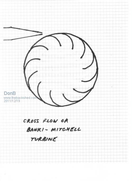
Don B |
||||
| herbnz Senior Member Joined: 18/02/2007 Location: New ZealandPosts: 258 |
Hi Dc high voltage is the way to go. All my attempts to use the Ac 3 phase have created losses due to the high frequency I have posted before tests on this connot find now tho. Warpspeed We have visited the area of dc dc converters before a few years OK they got linked to Mppt and the subject was shutdown. I have in isolation carried on working here with old pc supplies and now have a commercial solar MPPT Tristar that allows 150v max this works a treat I have had it on both wind solar and hydro. your find of a battery charger is good value as this Tristar cost $700, there is a fully setup commercial unit that does all three Midnite Classic available up to 250v input but cost is $1200 +. Ok tho one thing you must remember is as the batteries become charged and load is backed off the input voltage will go up to double ( in a well designed hydro) a voltage clamping cct is needed before the charger to dump load in this case. I have build various ccts out junk round here but I am sure you could come up with a better design. Don I have here in a text book a detailed design of a banki with all measurements an formulas I have also seen on the Net but cannot find now but here is a link to a site that has some detail http://www.cd3wd.com/CD3WD_40/VITA/BANKITUR/EN/BANKITUR.HTM Herb |
||||
| Warpspeed Guru Joined: 09/08/2007 Location: AustraliaPosts: 4406 |
Just to throw another curve ball into the ring and confuse John even more, how about the exhaust turbine from a turbocharger ? These are a radial inflow turbine, exactly the same as an ultra mini Francis water turbine as used in all the low head high flow hydro applications. The geometry and principle of operation is absolutely identical. The turbine wheels are made from high temperature austinitic stainless steel that absolutely will not rust. And high precision scroll volutes come in a variety of flow/nozzle sizes. The turbine wheels are beautiful things with very complex compound curves, and should be super efficient with water. Unlike a reaction turbine, these use all of the blades right around to generate torque, not just one blade at a time. So in spite of the small diameter wheel, torque should be quite high. If the idea has any appeal at all, I will see what I can dig out of my junk pile for you to experiment with. 


Cheers, Tony. |
||||
| Gizmo Admin Group Joined: 05/06/2004 Location: AustraliaPosts: 5078 |
Hi Don. Thanks for the info, I might go for the Banki-Mitchell wheel in my own set up. Glenn The best time to plant a tree was twenty years ago, the second best time is right now. JAQ |
||||
| BobMann Senior Member Joined: 30/06/2011 Location: United StatesPosts: 134 |
No reason it should lose any power at all running with dc input instead of ac input. Hello I found a few golf 110 volt input USA chargers one with 24 volt output. and one that is 36 volt out put.I know some can be rewaired inside to work as 220 volts. Seeing that you have a handle on this if I hit the 110 units ( say if I can not change to 220) with the higher volts from my Mann Smart drives with it will it jump the output by 2X. I have grid ties that work with 24 to 50 volts?? Bob Mann |
||||
| Warpspeed Guru Joined: 09/08/2007 Location: AustraliaPosts: 4406 |
No reason it should lose any power at all running with dc input instead of ac input. Hello I found a few golf 110 volt input USA chargers one with 24 volt output. and one that is 36 volt out put.I know some can be rewired inside to work as 220 volts. Seeing that you have a handle on this if I hit the 110 units ( say if I can not change to 220) with the higher volts from my Mann Smart drives with it will it jump the output by 2X. I have grid ties that work with 24 to 50 volts?? Bob Mann If the output is regulated to charge a 24v or 36 volt battery, that is what it will be. If the input voltage is far too high, the charger will probably just blow up and need repairing. Cheers, Tony. |
||||
| yahoo2 Guru Joined: 05/04/2011 Location: AustraliaPosts: 1166 |
I have wondered myself why a low head propeller style generator would not be very practical for smaller systems 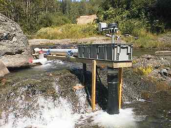
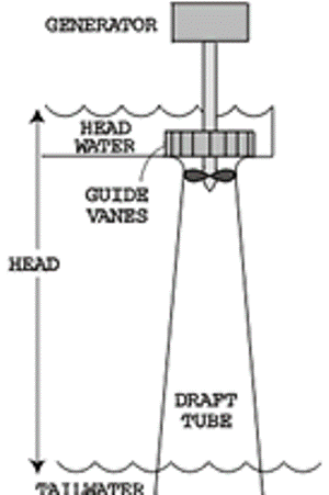
credit these are from microhydropower.com I can think of a number of ways to design a setup with a 2 or 3 metre head with off the shelf channel irrigation equipment or perhaps using piping down the river bank and then out a small jetty. I feel that the peltons only start to really shine with high pressures and 10 Kw+ generators. High pressure equals $$$$ setup cost and frequent frustrating fiddly f#@%* maintenance. yahoo I'm confused, no wait... maybe I'm not... |
||||