|

|
Forum Index : Windmills : Measuring cogg
| Author | Message | ||||
| Highlander Senior Member Joined: 03/10/2006 Location: AustraliaPosts: 266 |
Hey Bernie I'm a newbie too, only been into this for about three months, so someone else can give you a technical reason why, but yes if you short the terminals it will be incredibly hard to start. I think some people use this as a braking method, but shouldn't be attempted while the blades are spinning fast, a bit like putting a car in reverse while doing 100klm/hr. I'm sure someone else will elaborate. Do the test with no load at all, no props or prop hub and string wound around the largest od of the magnet rotor. Dwyer I did a search on soft rivets so no need to answer the question. I thought these might be good too. http://www.emhart.com/products/pop/grooved.asp I won't be able to have the rivet protruding to the far side so the grooved may be the one. Dunno how easy they are to get  Central Victorian highlands |
||||
| Pt w/field Matt Senior Member Joined: 24/02/2006 Location: AustraliaPosts: 105 |
hi highlander wouldnt contersunk head stainless steel pop rivets do? matt down south |
||||
| dwyer Guru Joined: 19/09/2005 Location: AustraliaPosts: 574 |
Highlander Thank for your information about company call Emhart product as is very handle dwyer the bushman |
||||
| Highlander Senior Member Joined: 03/10/2006 Location: AustraliaPosts: 266 |
G'day Matt, I don't know if normal rivets will do the trick as they require the body to pass through the material being used. The grooved was the only one I found that didn't need this. It appears to act like a mini dyna bolt. I tried to tap a thread in a stator finger and it's a bit messy due to the laminations. I rang coventry fasteners and they sell a countersunk self tapper, that may be an option as well. I'll go down and buy a few of each on Sat and test them out. Central Victorian highlands |
||||
| Highlander Senior Member Joined: 03/10/2006 Location: AustraliaPosts: 266 |
Hey guys, while I'm waiting to fix these plates on I thought I'd start with the neo rotor. I can have three lines of neo's with different pattern options. #1 have them all vertically aligned in three rows. #2 have a stagger reversed to the slant of the T plates. I like the second one.Perhaps 1.5mm stagger between each row, total of 3mm added sweep Any thoughts on that? 
I don't think it will work with the T plates as the gaps are so small but I still think this is a good idea, if airx use it there must be some merit in the principal. http://www.thebackshed.com/Windmill/FORUM1/forum_posts.asp?T ID=222&PN=6 Central Victorian highlands |
||||
| Megawatt Man Senior Member Joined: 03/05/2006 Location: AustraliaPosts: 119 |
G' day Highlander, If you can manage the T plates in the end, maybe the vertical arrangement of magnets would be OK. But as Gizmo has recently discovered, one of the reasons for the new F&P having reduced cogging is that they have arranged their magnets like a "greater than" or "less than" sign, or maybe you could describe it as a V turned through 90 degrees. I would guess that neos are so strong that cogging could rear its head again, like it did with brucedownunder2's adventurous rotor. (incidentally brucedownunder2, have you been game enough to drive that rotor up with a big drill to measure volts and amps out?) So I would tend towards the sideways V for neos, but it's a suck it and see thing, like much of the work going on in this area! Megawatt Man |
||||
| Highlander Senior Member Joined: 03/10/2006 Location: AustraliaPosts: 266 |
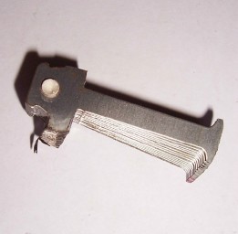
Hey Megawatt, yeah I saw that but those magnets interact with a strait pole 90 deg to rotational travel. With the slanted T I thought an arrow or a strait line may concentrate the field in one area ie cogg. The opposite stagger may help a little, I'm not really that sure or worried about it. Just something to tinker with really. I'll get there eventually. I had a go with plain old self tapping counter sunk screws and they worked fine. They survived quite a few blows with a heavy hammer without coming loose. I'll start again with a fresh stator on the weekend If anyone is interested, this is what the inside of a pole finger looks like. At the base they are all connected, so it must be die cut as a big ring shape and all stuck together, then the plastic former is applied somehow. I was a bit off with my estimate the micrometer said 4.5mm wide.  Central Victorian highlands |
||||
| dwyer Guru Joined: 19/09/2005 Location: AustraliaPosts: 574 |
hi Highlander Can you able send me a copy of your measure on small steel place and l will give a try by useing stainless mig wire and got some special silicon welding wire over in next few days and let you all know the result .  
Dwyer the bushman  |
||||
| Highlander Senior Member Joined: 03/10/2006 Location: AustraliaPosts: 266 |
Dwyer, thanks for the offer to test mate. 
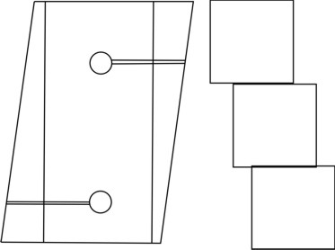
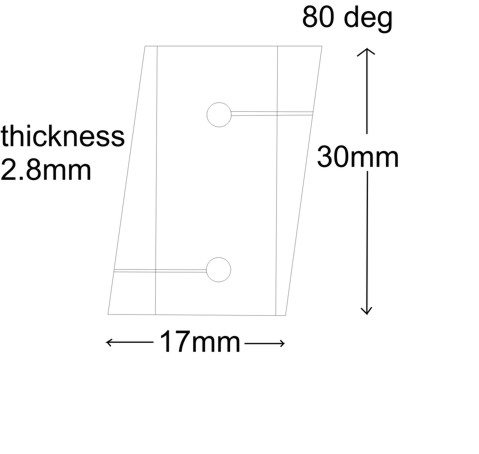
I think the countersunk self tappers and loctite glue combination will be ok. But if you want to try it the measurements are: 
(hole size 4mm) It might be a good idea to use exactly the same material I was using to get an exact replication of the test. Can I mail you a few plates? Email link in profile if you want to send your details. No need to bother really I think glue & screw will be fine. Thank you very much for the offer 
Now this part is theory from my limited knowledge. Before these plates are fixed on for eternity, I thought they will create more field down the finger, so is it worth winding on more turns of wire to capture any extra current that may be a result of the T plates and extra neo's? Might be a silly idea but no harm asking. Central Victorian highlands |
||||
| KiwiJohn Guru Joined: 01/12/2005 Location: New ZealandPosts: 691 |
Frankly, Highlander, I dont see any advantage in messing with the windings. |
||||
| RossW Guru Joined: 25/02/2006 Location: AustraliaPosts: 495 |
Just for the record, and as an indication.... I run a 48V system here, and a 1000W turbine. I use a large double-pole switch for the brake to join all 3 phases together. A few weeks ago, in order to test just how much current it pulls, and how fast it could be going before I could safely engage the brake, I did this simple test. In light wind, the turbine was outputting just on 10% of its output (about 2 amps, peak rated is 20A) when I hit the brake. Immediately the current shot up to 16 amps per phase. As the blades slowed, it quickly dropped, as you would expect. The point was - even at that low speed, throwing the brakes on was enough to take the windings close to their maximum current. If it was making say 5 amps, or more, I am pretty sure it would be a large enough surge current to either blow the switch apart, or the connecting cable, or worse, the generator coils. Thats not to mention the enormous and instant forces on the prop and driveshaft itself, which may shear! In short: from my experriments, NEVER throw on a regen brake if you're making more than about 10% of rated output. RossW |
||||
| Highlander Senior Member Joined: 03/10/2006 Location: AustraliaPosts: 266 |
G'day KiwiJohn, yeah I get a little ambitious at times 
with the 7 phase you have to cut all the connections so I thought why the hell not, I have to cut them all anyway, not that big a deal to wind on a bit more. So what your saying is it won't add current? Or it's not worth the effort? Anyone else with a view on this? Hey RossW thanks for that, I didn't realise they were that touchy. Good info thanks for the warning  Central Victorian highlands |
||||
| Highlander Senior Member Joined: 03/10/2006 Location: AustraliaPosts: 266 |

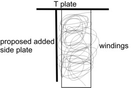
Excellent! Screws are working perfectly. I started with the fresh stator today, I had to cut new plates so the screw holes were perfectly centred. I bought some 406 locktite glue to give an added bond. This was very interesting, a quote from eco inn web site. "The Smart Drive generator cannot be burnt out as the core of the generator saturates and will not produce more power than 600 Watts regardless of the wind speed." Can anyone confirm this? So if this is right adding a heap of neo's won't help at all. Now guys how do we combat that? I'm assuming he means the finger core, when I cut one up this is clearly pretty thin (4.5mm). As far as my rough understanding goes the manetic field goes down the finger and causes electrons to move through the windings. If the finger core is saturated at 600 watt it would be extremely difficult to add metal inside. But would it work if metal was glued to the side of the windings and touching the T plate at the top?  Central Victorian highlands |
||||
| Pt w/field Matt Senior Member Joined: 24/02/2006 Location: AustraliaPosts: 105 |
-hi highlander why not run 2 stators or even 2 mills and be happy with that,you can only get so much power out of a set of blades not unless your site blows a cylone all day every day matt down south |
||||
| KiwiJohn Guru Joined: 01/12/2005 Location: New ZealandPosts: 691 |
Highlander, my comment regarding not being worth it to fiddle with the windings was my thinking that change just one thing at a time if you want to make progress rather than confusion. I dont think the side plate would be a good idea, you see as the lines of flux flowed down the side plate the associated field would cut both sides of the coil and what voltage is induced on one side of the coil would be offset by an opposite voltage induced on the other side. I am happy to be corrected on this.  |
||||
| Highlander Senior Member Joined: 03/10/2006 Location: AustraliaPosts: 266 |
Matt, VERY good point. It is very windy up in the mountains though. KiwiJohn, I thought of adding wire now because adding after the T plates are fitted it will be way more difficult. I gave up on that after your comment and T plates are being fitted now. As for the side plate I thought it would effect the coil next to it, but it was worth asking. I just unwound a coil on a old stator and picked off the plastic, added 1mm plates to the sides of the core and rewound the wire. It took about 1 hour and in my opinion the possible advantage wouldn't be worth the time to do the whole stator. It appears that these are limited to 600 watts. So the T plates won't add any current as the core won't hold any more than that. The only thing they'll do, PERHAPS is reduce cogging and smoothen the current flow. The thing now to be carefull of is not adding too many neo's past the point at which it will produce 600 watts, as this will only increase cogg and not add current. Does that sound about right? Central Victorian highlands |
||||
| Pt w/field Matt Senior Member Joined: 24/02/2006 Location: AustraliaPosts: 105 |
hi highlander you could do what adelaide p8 2f&pcar aircond clutch 12 footblades has done but use a 7 phrase cogless on the main shaft with a 100parael stator on the second shaft with 3to 1 gearing to spin the f--k out of it or a twin on the blades with different cut in speeds and a big output stator on the second shart with the cut in relay set that it wont cut in untill the blade stators are nearly maxed out, food for thought, see innovation information smart drive site 135KB pfd theres good graphs on output and rpms,what voltage are you running? matt down south |
||||
| Highlander Senior Member Joined: 03/10/2006 Location: AustraliaPosts: 266 |
Whoa !!!  , Matt that looks nice, how did I miss that, I thought I went through all the old posts. , Matt that looks nice, how did I miss that, I thought I went through all the old posts.
Dunno if I have the time for that. Maybe one day. I was basically trying to see how much you can get out of one stator, as this is relatively easy to build. If it's 600 watts then so be it. Once I know just how hard you can push 1 stator then I can plan a twin. Voltage I'm running? None YET. This is my first mill I made the frame over two weekends roughly two months ago but got distracted with neo's and then T plates. But I'm setting up for 12v. BTW T plates are half fitted, everything always takes twice as long as I plan. 
And never enough time to do it in. Central Victorian highlands |
||||
| dwyer Guru Joined: 19/09/2005 Location: AustraliaPosts: 574 |
|
||||
| Pt w/field Matt Senior Member Joined: 24/02/2006 Location: AustraliaPosts: 105 |
hi dwyer try page 8 of this forum general windmill chat matt down south |
||||