
|

|
Forum Index : Windmills : My new mill
| Author | Message | ||||
| vawtwindy Newbie Joined: 23/10/2010 Location: IndiaPosts: 31 |
waiting for the updates mate.. |
||||
| VK4AYQ Guru Joined: 02/12/2009 Location: AustraliaPosts: 2539 |
Hi All I am getting to the fun end of the project now, the next thing to do was to do the balance of the blades, they where set up as in the photo with the whole assembly carried on bearings with seal removed the grease washed out and lubricated with sewing machine oil, this allows for very low rotational drag, to do the final balancing. 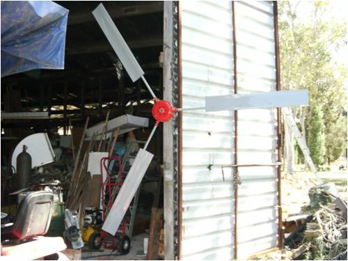
The blades where balanced with paint added to the blades as required to bring them to the same weight. All this sounded very good and workable but balancing the assembly with the stator in there as well resulted in a slight miss balance due to the terminal block on the stator and the wiring being on one side of the stator. Unfortunately this has resulted in a slight vibration of the mill when its running, so another balance is needed in the near future. This is the mast head adapter, it has a flanged coupling to the top of the mast for ease of assembly, in the picture it is showing the two bearing seats, the lower bearing is a ball race thrust assembly to carry the weight and allow smooth rotation. The upper bearing is a precision needle roller bearing to take the side thrust, it goes directly on the adapter shaft and has a sleeve on the outside to fit the machined surface inside the head adapter. This is a well engineered rotation system. 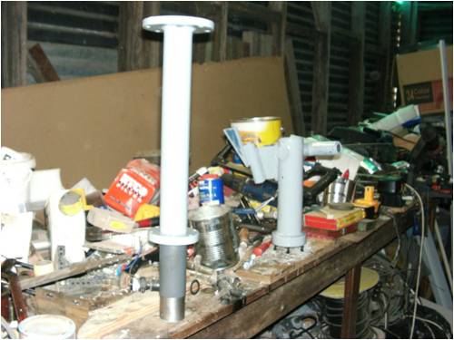
The wire comes up inside the mast and I clamped the mast wire inside the adapter flange, and terminated with a multi wire connector the same as the one in the stator, this allows the head to be disconnected without disturbing the wiring. From this terminal there are two wires per phase going to the underside of the wire slip ring assembly. The next photos are from Phills photo file, Thanks Phill. I used spade terminal for the connectors as they are more substantial than a conventional connector, and they fitted in very nicely with a small trim on the edges to fit them in the slots, on the bottom there are two connectors per slip ring as the connection screws are small it allows two paths for the current from the slip ring. The upper connections use a spade terminal but with a yellow sleeve as this takes the 3mm wire coming from the alternator. 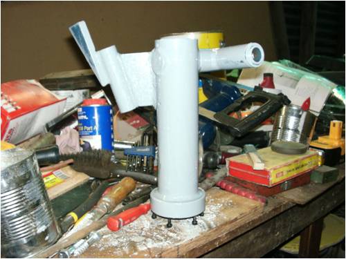
This is the head assembly that the alternator shaft is locked into, it also has the furling assembly and connects to the top of the slip ring assembly, The main shaft on the alternator goes into the mounting sleeve and is retained with two grub screws, these proved to be soft Chinese steel thats not worth a pie, I replaced these with two 3/8 UNC grade 8 bolts and nyloch nuts to lock them in place. I drilled the hole right through the sleeve to allow the thicker wire to go out the back without doing the twist and turn to fit the wire internally, a cover was made out of a asparagus tin that was just the right diameter to fit to the top of the head fitting a hole in the side of the tin 3/8" was finished with a screw driver shank to remove the sharp edge and 2 layers of heat shrink was fitted to avoid the silicone wire abrasion. A terminal block is fitted under the cover, this is to allow the alternator to be removed without disturbing the head assembly and slip rings. 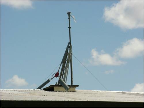
The tower was made of the top section of the kit tower to get the mounting flange sleeved to fit a 2" gal water pipe, a set of 3 attach points where welded at this point for bracing to the roof. The 2" pipe is clamped to the shed structure at 4 meters height and had a angle welded on the end thats bolted to the floor. The wire down from the alternator is 2 - 3 wire extension 1.5mm power leads connected in parallel, it comes out a hole in the pipe at 3.6 meters up the pipe and thence to the electronics, Another story. The alternator was fitted to the head assembly from the top of a step ladder tied to the tower for stability, I made a platform that sits over the ridge of the roof so its not as bad as it seems. Bit scary while doing it though. 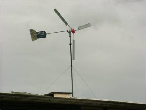
The tail proved to be a bit small so I fitted the extension in the above photo, this tracked better but is under revision in the near future, I am making a larger one to go higher and lower to equalize the spiraling effect of the wind stream. Another story if it works. All the best Bob Foolin Around |
||||
| VK4AYQ Guru Joined: 02/12/2009 Location: AustraliaPosts: 2539 |
The tale of the tail The original mill had smaller diameter blades 2.4 meter I think but my increasing the blades to 2.8 meter meant that the tail didn't have enough control of the blades and the mill wandered around in the wind aimlessly, Phill had supplied an extension kit for the tail boom the photo below is the original tail and boom. 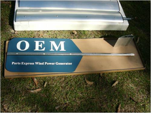
After fitting the tail boom kit lengthily the boom around 600 mm I tried it and it was better but still slow to react to wind changes. The next step was to shift the vane back by drilling out the rivets ans shifting it rearward by one rivet spacing, about 250 mm this was an improvement but still not happy with. 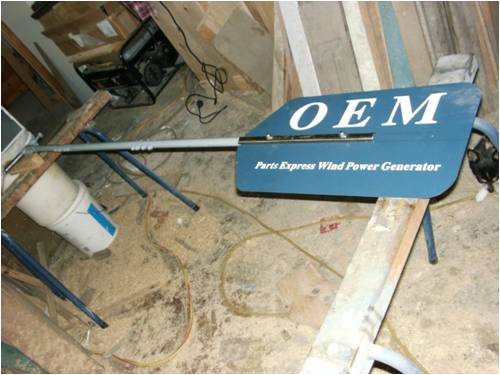
Phill knows best, in the end I fitted a bigger end on the vane as Phill had suggested and found the mill responded much better, and will now track wind down to .4 ms, this is very important for starting, as the mill needs to direct into what wind there is. The mill will now start consistently at .7 ms and starts generating at 1.2 ms, this charges the capacitors so when the the wind increases its ready to go. 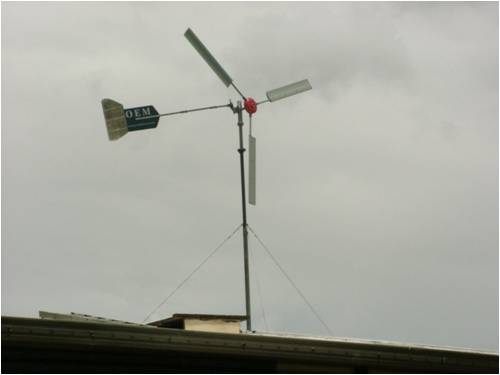
At this point in time the furling hasn't been tried as the wind is very light so cant report anything there. The furling angles where reset as per Phills specifications, so hope that will work out OK, the furling bracket was cut off the head and raised for the boom to be in line with the shaft of the alternator, the main reason I did this was, I cut the bracket of the head shaft and didn't want to weld it back on where it was as it may have caused distortion in the tube near the top bearing and cause it to bind, Phill said I should have cut the furling pivot bush off and re welded it, but I felt this may have caused binding in the furling action, so I did it the hard way as I usually do. I am considering a larger tail section in the future which will shorten the boom length a bit, but for the moment it is working and generating so will leave well enough alone, I found a steering damper of a motorbike that is fully adjustable and will fit that next time I have it down, this is to stop the tail whipping around and hitting the blades. Next week I will do a block diagram of the electrics set up, at the moment it is a work in progress, and still waiting for some bits to turn up. With what I am using so far the magic smoke has stayed in, so it is so far so good. All the best Bob Foolin Around |
||||
| GWatPE Senior Member Joined: 01/09/2006 Location: AustraliaPosts: 2127 |
Hi Bob, you are treading a dangerous path with your mods to the tail and the rotor. You need to check the effectiveness of the changes to the furling geometry to compensate for the larger rotor dia[higher torque and wind energy capture area, and the longer tail, means it is effectively heavier and therfore makes furling at a later, [higher] power level. I would err on soft furling first, and then change the angles to bring the top end power up in a controlled manner You are spending a lot of effort with the mods. Would be a shame to have a storm come through and the mill is hard to control. Do you know how much power the windmills produce at the 1.2m/s speed? Gordon. become more energy aware |
||||
| VK4AYQ Guru Joined: 02/12/2009 Location: AustraliaPosts: 2539 |
Hi Gordon It is a bit of an experiment all the way, the furling angles have been changed to suit Phill specifications, I feel however there is to much tail weight on the boom, I plan to replace the steel vane with an alloy one, shortened a bit but higher and lower to get more area, this will get the tail weight down by nearly 1 KG, I don't mind if it furls a bit early for safety, the damper will smooth things out a bit as well. I think it should have a bit more offset on the alternator as well with the bigger blade size. The power out at 1.2 is insignificant but enough to sync the GTI and show .5 amps on the meter, when it gets to 1.5 ms the doublers start to conduct as well, but only enough to move the needle on the amp meter. At that point it is showing 15 volts DC output. By this time it is putting 1 amp into the GTI http://www.youtube.com/watch?v=jaKdrkDKkD4 It amazes me to see the blades spinning when the leaves on the trees are hardly moving, when the wind get up a bit the old mill spins faster as it hasn't got the same loading, I took the cap doubler off it to try on this new one, next week I will fit the boost converter to it and try that, that should load it down as it boosts to 27 volts from 10 volts, another experiment. All the best Bob PS when the shorting switch is on it wont start in any wind I have had so far and is very difficult to turn by hand so If any bad weather comes I will just hit the stopper and leave it stalled. Hope that works.http://www.youtube.com/watch?v=jaKdrkDKkD4 Foolin Around |
||||
| GWatPE Senior Member Joined: 01/09/2006 Location: AustraliaPosts: 2127 |
Hi Bob, You seem to have special winds. The 1A is presumably at 15V, so 15W@1.5m/s. At double the wind speed, 3m/s, equates to 120W at the alternator, and about 1kW@6m/s, and 6kW @ 10m/s. I think the data is highly optimistic, but I encourage your enthusiasm. It is extremely difficult to get accurate data, and I think that a simple check with a wind energy calculator to confirm ballpark figures would be advisable. BTW Altons calculator has 4W of wind energy at 1.5m/s for a 2.8m dia rotor, so about 1W would be available through losses to any loading, and not 15W. I don't want to appear negative here but overstating windmill power does not help others with their own comparisons. It is highly likely that your meters are giving misleading numbers, possibly from a pulsed current measurement. I calculate accumulated Wh from the windmill on the DC side, and then compare the Wh from the AC power meters for the same time. I am within 10% usually for the comparison power of the 2 results in the same time interval. This accounts for efficiency losses and measurement errors, so I am relatively confident. I also correlate windspeed measurements between the windmill computer, and the DAVIS weatherstation. I think your system is possibly a candidate for more rigorous performance evaluation. Possibly something to look at soon, to help with future objective comparison testing. Gordon. become more energy aware |
||||
fillm Guru Joined: 10/02/2007 Location: AustraliaPosts: 730 |
Hi Bob, With the furling angles that I have tested for a 2.8m blade set I have to add the point that it will only work if the dimensions, lengths and weights are the same . If you change the loading (weight of tail) on the furl pivot angles then they will have to be adjusted accordingly . By looking at the way you have modified the tail it would be heavier than the mod that I did so the angles would need to be less . As the tubing is only 25mm I would advise you to fit the strainer support wire to take the weight of the tail . Appart from that Bob you have done a great job on documenting all you have done and hopfully now it all gets better as you fine tune what you have done . I still would recomend you try star for the best low wind performance with the 2.8m blades . PhillM ...Oz Wind Engineering..Wind Turbine Kits 500W - 5000W ~ F&P Dual Kits ~ GOE222Blades- Voltage Control Parts ------- Tower kits |
||||
| VK4AYQ Guru Joined: 02/12/2009 Location: AustraliaPosts: 2539 |
Hi Gordon I agree with the concern you have on the accuracy of the output, and am sure it is to do with the sampling rate of the weather station I am using as it does wind speed at a 5 minuet sampling rate and gust average at 1 minuet sample rate, I have tried to reduce these in the program, but it wont handle the higher sample rate, it locks up. My hand held anometer doesn't read accurately at such slow speeds as the encased turbine is very sensitive to direction and the wind through the trees is turbulent. Wind Speed Table base on Altons MS ----mph ---Tn ----TKg ----RPM ---W@B ---ST Kg/m 0.5-----1.1-----0.9-----0.1-----27------0------ 0 1-------2.2-----3.4-----0.3-----54------2-------0 1.5---- 3.4---- 7.7---- 0.8-----80----- 7------ 0.01 2------ 4.5---- 13.6--- 1.4-----107---- 16----- 0.02 2.5---- 5.6---- 21.3--- 2.2-----134---- 31----- 0.03 3------ 6.7---- 30.7--- 3.1-----161---- 53----- 0.04 3.5---- 7.8---- 41.8--- 4.3-----188---- 84----- 0.06 4------ 8.9---- 54.6--- 5.6-----215---- 125---- 0.07 4.5---- 10.1--- 69.1--- 7-------241---- 178---- 0.09 5------ 11.2--- 85.3--- 8.7-----268---- 244---- 0.12 5.5---- 12.3--- 103.2-- 10.5----295---- 325---- 0.14 6------ 13.4--- 122.8-- 12.5----322---- 422---- 0.17 6.5---- 14.5--- 144.1-- 14.7----349---- 537---- 0.19 7------ 15.7--- 167.2-- 17.1----375---- 670---- 0.23 7.5---- 16.8--- 191.9-- 19.6----402---- 824---- 0.26 8------ 17.9--- 218.3-- 22.3----429---- 1001----0.3 8.5---- 19----- 246.5-- 25.1----456---- 1200----0.33 Based on the problem of low speed accuracy I did an Altons calculation on the mill and thats the above table. Looking at this a slow speed error of <1 ms could account for the error. I can measure the RPM with a digital tacho and at 1.7 ms I am getting 136 rpm at the alternator. This mill starts rotating in much lower wind speed than suggested by Alton, my old mill is for all intents a replica of his start and power readings, as it more closely conforms to his test blade design. The new mill has significant advantage at very slow wind speeds, but loses out at higher speeds, indicating to me the low speed optimization of the blades, and as we know nearly anything will work at high speeds. As the measuring equipment is a haywire setup with analogue gauges there is also a error component built in. I am not trying to guild the Lilly with my observations but presenting them with the best of my ability with the equipment available. As time goes on and I can get a logger going then I hope it will be more accurate, However some of the interface conversions still leave a margin for error as we arn't talking about absolute accuracy with all facets compared to an absolute standard. The bottom end energy below 2.5 ms is so small as to be insignificant in the power equation into the system as a whole the gusts within the average wind speed along with the stored kinetic energy of the blade assembly contributes to the error due to sampling rate, as your logger has a much higher sample rate it will be more accurate and I look forward to getting one going. All the best Bob Foolin Around |
||||
| VK4AYQ Guru Joined: 02/12/2009 Location: AustraliaPosts: 2539 |
Hi All Finally some wind to see how the mill goes, today Saturday 12th December 2010 the long awaited wind came along, frontal winds to 12.5 ms gave the mill its first real opportunity to see what it can do. I took photos of the meters to validate the findings unfortunately the flash on the camera ruined the results. So here we go on unlogged observations. 2.5 ms resulted in 2 amps into the GTI at 13 volts and 0 amps through the doubler into the battery bank at 27 volts Total = 25 watts 3ms resulted in 4 amps into the GTI at 14 volts and .5 amps through the doubler into the battery bank at 27 volts Total = 75 watts 3.5 ms resulted in 5 amps into the GTI at 15 volts and 1 amps through the doubler into the battery bank at 27 volts Total = 105 watts 4 ms resulted in 8 amps into the GTI at 18 volts and 3 amps through the doubler into the battery bank at 27 volts. Total = 225 watts 4.5 ms resulted in 10 amps into the GTI at 22 volts and 3.5 amps through the doubler into the battery bank at 27 volts. Total = 314 watts 5 ms resulted in 12 amps into the GTI at twenty seven volts and 6 amps through the main rectifiers and doubler into the battery bank at 27.5 volts. Total = 490 watts 6 ms resulted in 12.5 amps into the GTI at 28 volts and 11 amps through the main rectifiers and doubler into the battery at 27.5 volts. Total = 640 watts 7 ms resulted in 11 amps into the GTI at 30 volts and 18 amps at 27.5 volts into the battery through the main rectifier and doubler. Total = 825 watts 7.5 ms resulted in 11 amps into the GTI at 30 volts and 26 amps at 27.5 volts into the battery through the main rectifier and doubler. Total = 1045 watts 8 ms Resulted in 11 amps into the GTI at 30 volts and off scale reading on amps on the main rectifier and doubler, possibly 40 amps as the amp meter was pegged over scale. Total = 1440 watts The higher speeds resulted in the amp meter being pegged so no recording. Also in the intermediate range the alternator was reading higher on gusts than these readings pegging the 30 amp meter for several minutes at a time, should have fitted the 50 amp meter. These readings where ignored. As my weather station has a gust time base of 1 minuet sample the readings are not absolute but I have used the smaller reading at the ms reading, so as not to over estimate the the output to any large extent. When I get a logger going I hope for more accurate assessment. The furling was starting at 8 ms and by 8.5 ms it was one third furled with no loss of output, I think I will have to reduce the tail weight to furl a bit earlier as I would like to see the machine fully furled by 10 ms. The shorting brake wasn't tested on this occasion as there where no lulls in wind speed to allow a safe test. The GTI system worked very well in conjunction with the doubler allowing good recovery of energy at low speed. The GTI reduced its output slightly as the power went up once it had reached MPPT saturation. I feel the slight reduction noted in the GTI was caused by the unit heating up over the test time. The Old mill up in the same wind produced less than half the wattage of the new one and by observation the blades on it where going much faster than the new mill, it was running a 300 watt GTI and direct rectifiers the 300 watt GTI was at full power and the highest output observed on the main rectifier was 15 amps once again into the 27.5 volt standing battery voltage. Approx 750 watts still not to bad for an old 500 watt unit. All the best Bob Foolin Around |
||||
| GWatPE Senior Member Joined: 01/09/2006 Location: AustraliaPosts: 2127 |
Hi Bob, the windmill certainly appears to be making good power. I have taken the liberty of plotting the data for you. 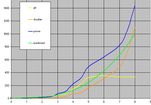
The graphs are according to the legend, and the X-axis is windspeed and the Y axis is Power. I have included the predicted power from Allton's calculator. It is interesting that the measured power is significantly greater than predicted from the windspeed. I think that there is still a problem with measured windspeed, but it is a good start. Windspeed is probably measuring 1m/s lower than it really is. The GTI seems to be working. I think those without a grid, but RE battery, would get similar results running the alternator in star, with only main rectifiers and a cap doubler. A small reduction in top end max power may be evident, but the wind distribution and load usage patterns would determine if this was significant. I think I can say a good result. Gordon. PS: The graphs show no signs of any change in output at the high power levels with windspeed. This indicates that furling is not close to being effective. The windmill potentially has the ability to make more current still. Take care as i^2R losses can take hold very quickly. become more energy aware |
||||
| Greenbelt Guru Joined: 11/01/2009 Location: United StatesPosts: 566 |
VK4AYQ; HI Bob, Again, Kudos to you and PHIL, That extended blade design puts out the torque when the Gen.loads up. Gordon's power graph gives a good picture of the performance of this mill. and if errors exist in your hurried calculations they could not be so great as to call this mill a failure. According to Allton's Calc. you should get a "maximum 1000 Watts @ 24 KM.PH. wind speed If you discounted 30% as an error in calc's you would still have 8 Watts more than allton Permits. I suspect that your errors are not that large. Good work Bob. Hope you get that Logger soon. best to you always, ---Roe EDIT; As Gordon suggested, you're getting close to letting the smoke out!. Time has proven that I am blind to the Obvious, some of the above may be True? |
||||
| VK4AYQ Guru Joined: 02/12/2009 Location: AustraliaPosts: 2539 |
Hi Gordon Thank you very much for plotting the output, it is a fair representation of what the mill can do. I think the discrepancy on the power to MS readings was due to wind variations within the read of the wind speed at 60 second intervals for gusts and 300 seconds for wind speed. The amp readings where actual and voltages as well. When the front came in I missed the first 10 minutes as I was on the phone, looking at the wind speed recording before I unplugged the readout to take it to the shed it was just over 25 ms for the ten minutes. I think the mill furled in that time but I didn't see it, by the time I got out to the shed it was furling to 50% at 12.5 mn Indicated, as the wind speed dropped back to the 8-10 ms range it was floating in the first stages of furling. For all intents it made no difference to the output as your graph shows. I think the reduction of 2 KG on the boom will do the trick, I would like to get it back to 10ms fully furled, or no more than 12 ms. The doubler passes 3 amps before the voltages equalize on the main rectifier, so that is working well, with the GTI disconnected it boosts a bit earlier due to the unloading of the alternator. Also I think these blades are more efficient than the representation in Altons calculations, based on the comparison to the other mill these blades start much earlier, I am sitting watching the two mills now the new mill is doing 80 rpm and the old mill is just creeping. Once again thanks for the chart. All the best Bob Foolin Around |
||||
| VK4AYQ Guru Joined: 02/12/2009 Location: AustraliaPosts: 2539 |
Hi Greenbelt Thanks for the encouragement, I am very pleased with the results so far but will have to reduce the furling speed to prevent lung cancer. The problem with the weather station record times makes it a indication rather than an absolute for wind speed, hope to have a logger going in January, that will stop the wind completely.I have a couple more things I want to try on the bottom end to salvage a bit more energy, but looking at Gordon's graph there isn't much in it to play with. These blades are more efficient at low speeds than the design that Alton uses in his calculator, with a C/L of 2.4 as compared to his at 1.3, I think that is part of the story, and also they wont spin up as fast as his due to the increase of drag in the L/D ratio. All fun and games All the best Bob Foolin Around |
||||
| isaiah Guru Joined: 25/12/2009 Location: United StatesPosts: 303 |
Bob and all, The mill we were working on I wanted to get it up before bad weather. Well bad weather won out, '  ' We took it down off the test stand and were in the process of some changes to put it in service on the tower . ' We took it down off the test stand and were in the process of some changes to put it in service on the tower .
If the bad weather breaks Ill try to put it up and maybe get some pictures, Bub73 will have to teach me how to post them. '  ' '
I have one 12 volt mill running and I have a 12v led truck clearance light on it. The light begins to light up about 6 -7 volts, Is there a way I Could adjust this up to where it wouldn't come on til about 12 volts? At this time I cant afford a pick logger or data logger. I do have a bag full of these led lights that Bub73 and I probably could let the smoke out of a few!!'  ' 'URL=http://www.motherearthnews.com/Renewable-Energy/1973-11- 01/The-Plowboy-Interview.aspx>The Plowboy Interview[/URL> |
||||
| VK4AYQ Guru Joined: 02/12/2009 Location: AustraliaPosts: 2539 |
Hi Isaiah I have used a led voltmeter kit to switch things at different voltages it needed a few extra transistors and some pots for different voltages. Sorry to hear you have bad weather now same here the last two days at my place have been 36 deg C, so not much work done, I was riveting up my set of blades for the next project but stopped due to so much sweat I couldn't see through my glasses any more. My computer is having a go slow as it is to hot. All the best Bob Foolin Around |
||||
Downwind Guru Joined: 09/09/2009 Location: AustraliaPosts: 2333 |
Not sure on what you mean "adjust this up to 12 volt" The only way i can see is to have it switch on at 12 volt. Bub73 is pretty handy with a soldering iron and a few opamps so he should be able to set you up a controller circuit to cut in at 12 volt (apposed to cutting out at 14 volts) A data logger don't need to be an expensive item and a simple 08m picaxe chip (about $3.00) and a couple of resistors, and you can log the voltage. Then as the $$ are spare add some circuitry to log the current, and then the rpm. It don't need to be a bells and whistles logger to enjoy some recorded data, In actual fact you will learn more by going step by step. Happy to help you if needed with some simple programming and Bub73 is quite adapt with electronics, and able to assemble a vero board project to start with. Pete. Sometimes it just works |
||||
| isaiah Guru Joined: 25/12/2009 Location: United StatesPosts: 303 |
Bob, 10 deg.F here with blowing snow. What we need to do is find a way to split the difference in this weather! You could email me some heat cheaper that I could email you the cold.Any ways it should balance out. the old fingers and bones don't work well in the cold and 44 yrs in a shop on a cement floor don't help either. Pete Bub73 and I discussed using one of the old charge controllers. but after he ever gets his laptop working we may move on to some better circuits. We have been catching up on some small things for future projects inside. I just got a small stepper motor that tests out good for a mini mill so Im collecting things for that. Looks like it may be a long cold winter here. URL=http://www.motherearthnews.com/Renewable-Energy/1973-11- 01/The-Plowboy-Interview.aspx>The Plowboy Interview[/URL> |
||||
Downwind Guru Joined: 09/09/2009 Location: AustraliaPosts: 2333 |
You want to do what the squirrels do when its cold ..... tuck your nuts away. 
Tell Bub73 to pull his finger out, and move up to the world of micros and have a fiddle with a picaxe, im sure he will master it in little time and have lots of fun, designing alsorts of circuits. Pete. Sometimes it just works |
||||
| VK4AYQ Guru Joined: 02/12/2009 Location: AustraliaPosts: 2539 |
Hi All Another storm front today 36 C stirred up a strong front that came through around 4 pm 20 + ms winds for half an hour once again pegged out the amp meter but I was more interested in watching the furling, or should I say lack thereof. Watching the furling it would start to furl then the blades just pulled back into the wind and kept going, the tail was wagging like a dogs tail but no significant furling. This indicated a lack of offset on the mill, in this case around 5 inches, apparently not enough for the bigger blades, the larger tail proposed will stabilize the tail somewhat,and the lower weight should bring in furling earlier, this may allow furling before the blades lock into the wind and are held there by gyroscopic forces that the furling cant overcome. I will be aiming for a furl at 10 - 12 ms allowing full output of 1500 watts but not allowing the blades to accelerate to the point of having enough gyro forces to negate furling. The electrical systems are working well so no issues there but are a bit overloaded with to much power, today over 2000 watts but no magic smoke. This indicates to me that if the control is established with the furling, the rest of the works is a real success. All the best Bob Foolin Around |
||||
| VK4AYQ Guru Joined: 02/12/2009 Location: AustraliaPosts: 2539 |
Hi All I have been thinking and researching the action of the mill today, I was puzzled by the sideways nodding action of the propeller disk as it started to furl then pulled back into the wind, thereby wagging the tail vane, showing that it was trying to furl but another force was in action. I think I have found the answer but would welcome the input of those more knowledgeable in the VAWT machines than I am. My thoughts after looking up my helicopter handbook are this:- As the blade starts to furl the angle of attack of the blades varies in relation to the direction of the mass of airflow, The blade that is swinging into the wind develops a higher angle of attack anf therefore a higher C/L in the relative air mass flow, and the side of the blade swinging with the air mass develops a lower relative angle of attack, and therefore a lower C/L, at the same time. The resultant of these two actions is that the center of pressure of the disk is displaced towards the higher lift side of the disk thereby opposing the furling as the center of pressure shifts out past the offset of the disk in relation to the furling pivot. This is taking into account that the center of pressure is behind the disk, and in real terms is a center of lower pressure causing the displacement of energy towards the side that should be swinging forward. This would account for the nodding in the horizontal plain I observer, as I couldn't relate that to the gyroscopic force of the disk, that was evident in a vertical nodding in the mast head that was also present. There are a combination of forces at play, but I think the shift in the center of pressure of the disk is the main culprit I would appreciate a few expert comments on my eccentric conclusion. I probably have made a great discovery for me but is a ho hum effect to the experts in the field. Over to you all. All the best Bob Foolin Around |
||||