| |
  Page 4 of 6 Page 4 of 6   |
| Author |
Message |
KarlJ

Guru

Joined: 19/05/2008
Location: AustraliaPosts: 1178 |
| Posted: 11:40am 03 Jul 2010 |
 Copy link to clipboard Copy link to clipboard |
 Print this post |
|
i've said it before and i'll say it again
what would we do without OZtules...
geez OZ i'd kill to know just the stuff you've forgotten.
RESPECT!
Karl
Luck favours the well prepared |
| |
VK4AYQ
Guru

Joined: 02/12/2009
Location: AustraliaPosts: 2539 |
| Posted: 01:40pm 03 Jul 2010 |
 Copy link to clipboard Copy link to clipboard |
 Print this post |
|
Hi Mack
Going along well mate and I really like your plastic magnet locater, it should be a really nice alternator now you have upgraded the magnets. Have you worked out a coil turns ratio yet or doing a suck it and see?
Saw one of my snakes today when shifting timber to make a wing transporter, just looked at me and went back to sleep as it was 10 C. in the shed.
All the best
Bob
Foolin Around |
| |
GWatPE
Senior Member

Joined: 01/09/2006
Location: AustraliaPosts: 2127 |
| Posted: 02:56pm 03 Jul 2010 |
 Copy link to clipboard Copy link to clipboard |
 Print this post |
|
Hi Mac,
You wrote :-
" All you do is choose the correct face alignment and slide
each magnet across the plastic until it snaps into the hole in the
plastic sheet, which is mounted to the iron magnet-backing plate."
This is really no way to treat magnets.
Magnets should be slid into position as any sharp knocks can change the magnetic dipoles within the magnet, and even cause the magnets to break apart.
the alignment tool pic, I posted a while back allowed the magnets to be slid into position.
Gordon.
Edited by GWatPE 2010-07-05
become more energy aware |
| |
MacGyver

Guru

Joined: 12/05/2009
Location: United StatesPosts: 1329 |
| Posted: 12:11am 04 Jul 2010 |
 Copy link to clipboard Copy link to clipboard |
 Print this post |
|
[Quote=VK4AYQ] . . . doing a suck it and see?
Yup!
[Quote=GWatPE] This is really no way to treat magnets.
C'mon! It's just a little "snap", no biggie, really. Then again, maybe it's a good thing I bought 100+ of the little rascals, eh? 
. . . . . Mac
Nothing difficult is ever easy!
Perhaps better stated in the words of Morgan Freeman,
"Where there is no struggle, there is no progress!"
Copeville, Texas |
| |
niall1

Senior Member

Joined: 20/11/2008
Location: IrelandPosts: 331 |
| Posted: 11:12pm 04 Jul 2010 |
 Copy link to clipboard Copy link to clipboard |
 Print this post |
|
hi Mac
concerning the neos you can make use off the soft nylon spacers that come with them if you want....grind down one to a wedge shape and place it under where you want the mag
to go in the jig (you may have to adapt it for this ) ...leave it proud a little so you can pull it out gently..this,l let the mag slowly down onto the rotor with a minimal click ..if any at all...you may have to push it fully in a couple of mill in to the jig when the wedge is out....you can add a small dot off adhesive on one or two edges if your concerned that the mags might wander when the jig is removed ..(prior to casting)...but this is a personal choice ...
small neos arnt to bad to handle...i,ve snapped the first few i had on as well ,but its not really the best ...as far as i can tell there just a lot off magic powders compressed into a block
bigger block ones do need very healthy respect ....they give me the creeps just looking at them in a box....Edited by niall1 2010-07-06
niall |
| |
MacGyver

Guru

Joined: 12/05/2009
Location: United StatesPosts: 1329 |
| Posted: 11:51pm 04 Jul 2010 |
 Copy link to clipboard Copy link to clipboard |
 Print this post |
|
niall1
Let me elaborate a little on my procedure:
What I do is get a whole line of these little neos and use the rest as a sort of "handle" to shove one into a hole. The only "snap" or "click" is the last about 32nd of an inch if that much. I'm able to insert the things almost completely before they get a mind of their own.
Once I've inserted a "N" face, I revolve the row of magnets in my hand and insert one from the opposite end. Back and forth I go until all the holes are filled and that gives me a N-S-N etc. configuration.
I used the plastic (grey in the pictures) holder thing as a way to keep track of stuff and assure even spacing. Also, as it whirls past windings of wire, the smooth exterior of the wheel is a little less scary should there be a stray something or other hanging out waiting for something to catch it as it passes.
. . . . . Mac
Nothing difficult is ever easy!
Perhaps better stated in the words of Morgan Freeman,
"Where there is no struggle, there is no progress!"
Copeville, Texas |
| |
niall1

Senior Member

Joined: 20/11/2008
Location: IrelandPosts: 331 |
| Posted: 12:19am 05 Jul 2010 |
 Copy link to clipboard Copy link to clipboard |
 Print this post |
|
hi mac
i can see now how your using the placement method ...it seems to work well with the neo size you have .....not letting them get a mind off their own as you say is the critical bit......
i,m just always a bit of a worrier about handling neos .... 
niall |
| |
MacGyver

Guru

Joined: 12/05/2009
Location: United StatesPosts: 1329 |
| Posted: 10:35pm 05 Jul 2010 |
 Copy link to clipboard Copy link to clipboard |
 Print this post |
|
Update 7-5-2010
Building The Stator
This is the part that gets into actually making the electricity. The stator consists in this case of 9 coils arranged in a circle and stuck in place with epoxy resin.
First off, I built a little gadget to wind the coils with using my lathe. As easy as this might sound, it was actually anything but easy.
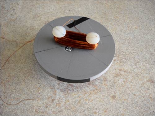
Here's what I came up with. It's a sheet plastic disk screwed to a plastic
hub. Everything was spun and cut on center. I added two 1/4-20
plastic bolts, which serve as posts on which to wind the wire. That
black stripe is so I can count the turns as it spins chucked in my lathe.
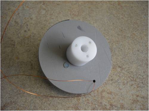
Here it is from the back side showing the three little 6-32 threaded holes
that house the three screws, which hold the plate to the hub. That small
hole in the grey plastic is a "keeper" used to hold the starting end of wire
while the coil is wound about the two plastic screws on the face.
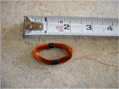
Here's one completed coil. Note the size; it's tiny. Nine of these little
rascals will share the space between the two 12-magnet wheels.
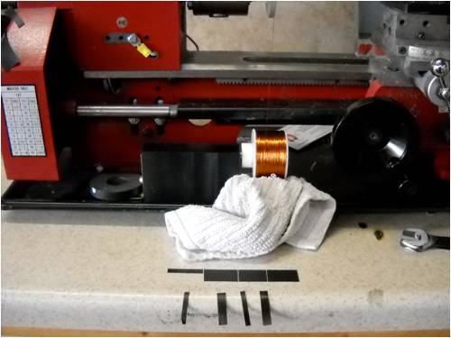
I manufactured a spool holder and stuck it to my lathe bed using a
magnet (temporary mounting). The towel adds "drag" to the spool of
copper wire. I found out the hard way what happens when an unbridled
spool of wire traveling too fast gets away; bird's nest mess! The towel
slows the feed and I put the lathe in "granny gear" and ran it way slow!
Those little black strips are electrical tape that have been scored with
a razor knife. I use them to tape the sides of the coils so they won't
unravel.
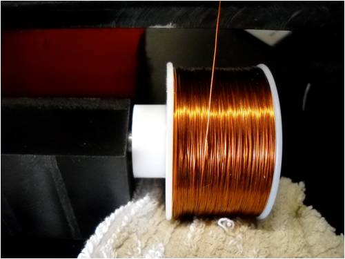
This shot shows the spool of copper wire and the rag underneath
helping slow it down so it doesn't get ahead of itself and make a bird's
nest.
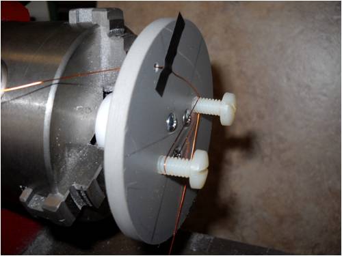
This is the winding plate and those two nylon-plastic bolts. The little
hole keeps the end of the wire out of the fray. I also tape the wire
where it goes through the little hole in the plate. This keeps it tight
against the plate and not interfering with the rest of the windings. A
small piece of tape on the circumference gives me a visual cue as to
how many turns the thing has spun. These coils each have 150 turns.
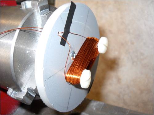
Here is one 150-turn, 30-gauge enameled copper wire coil ready to
be taken off the winder.
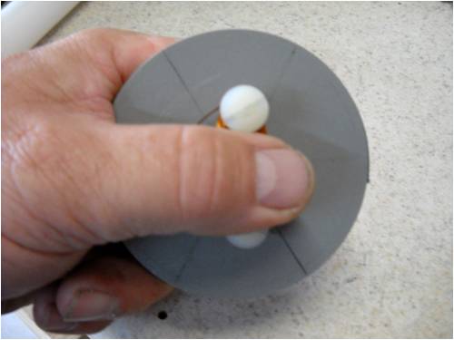
Remember to hold the coil so it doesn't jump off and make a mess
when the turning-peg screw is removed. I just slipped the coil over
the top of the remaining screw and taped each leg with electrical tape.
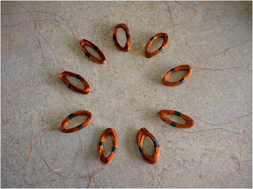
Here are all 9 coils arranged in a circle. The next step is to make a mold
and encase all these coils in epoxy. Something to keep in mind is the
direction of the wire in the coils. When three coils are tied together
forming a single "phase" you'll want to know which wire is which. If
you hook it up backwards it won't do diddly; we don't want that!
As soon as I figure out the "potting" process, I'll post the resulting build here, so stay tuned for the next installment. For now, I'm finishing up some 4-foot Coroflute blades, which are 3" at the root and 2" at the tip. They should be fast as well as powerful and provide more than enough power to crank this little ax-fx!
. . . . . MacEdited by MacGyver 2010-07-07
Nothing difficult is ever easy!
Perhaps better stated in the words of Morgan Freeman,
"Where there is no struggle, there is no progress!"
Copeville, Texas |
| |
oztules

Guru

Joined: 26/07/2007
Location: AustraliaPosts: 1686 |
| Posted: 08:05am 06 Jul 2010 |
 Copy link to clipboard Copy link to clipboard |
 Print this post |
|
Seems a lot of spare real estate there.
Those magnets are 1/2" X 1/4" by the looks of it, that means your magnet gap will need to be less than 3/8" thick.... so a stator in the order of 1/4" thick max.(plus 1/16th inch air gap each side)
It may better that you just wind round coils, 1/8" thick with a 1/2" hole (use a 1/2" former), and see if that will fit.... you still need a bit of glass in there to help the resin have some body.... best not to use epoxy for the stator, fibreglass resin seems to handle this better.
How did you arrive at the turns number?.
...........oztules
Village idiot...or... just another hack out of his depth |
| |
MacGyver

Guru

Joined: 12/05/2009
Location: United StatesPosts: 1329 |
| Posted: 05:11pm 06 Jul 2010 |
 Copy link to clipboard Copy link to clipboard |
 Print this post |
|
[Quote=Oztules]How did you arrive at the turns number?
I fiddled around with it for a while, shooting for about a 1/4"-thick winding. I also figured out I could mash the windings down a bit (physically) before I cast them in place. When I divided the pie into 9 slices, the narrow end of the little wedges led me to make the coils such that I could make one a little "pointy" to make them fit better side by side.
I got all excited and made 9 coils so I could have my Kodak moment for the 4m post never testing anything. Guess I got a little ahead of myself there, eh?  I'll test one and see how much juice it makes, then either move ahead or start over. I'll test one and see how much juice it makes, then either move ahead or start over.
Everything in life needs balance. To that end, I think I must be the balancing act on the other end of the stick from actual engineers. There are those who do the math and "plan" ahead and then there's folks like me who just do it and hope it works.
And that's kinda how I came up with the number of turns. 
(Edit) Oz: Yes, those magnets are 1/2" diameter and 1/4" thick.
. . . . . Mac
Edited by MacGyver 2010-07-08
Nothing difficult is ever easy!
Perhaps better stated in the words of Morgan Freeman,
"Where there is no struggle, there is no progress!"
Copeville, Texas |
| |
oztules

Guru

Joined: 26/07/2007
Location: AustraliaPosts: 1686 |
| Posted: 11:12pm 06 Jul 2010 |
 Copy link to clipboard Copy link to clipboard |
 Print this post |
|
Somehow I guessed how the calculations were done 
Do a test coil. (or use one of those to get number of turns per volt at a fixed rpm). For a 12 volt system using your new corflute blades, and guessing a TSR=6, we get the following scenario.
For a little blade set like this, it will spin easy (because it is axfx), but not really worth saddling up until about 10 mph, unless it has good adjustable furling.
Even here, while there is 13 Watts available at the blade.... to aim for a lower cutin would give us much more extra resistance in the stator,..... so if we wind for lower cutin, resistance will likely cook the stator too easily, for very little gain... big blades for a little alternator.... we compromise.
So blades= 1.2M (4')
Cutin speed @ 10mph, rpm = 400 .
So @ 400 rpm we need to see X volts in a single coil
We want to see 13vdc @ 400 rpm.
So we multiply the 13vX .7 to get the AC voltage we would need to have to get the 13v peaks when we rectify. So our 13vX.7 = about 9.1vac
We will use star to get this voltage so each coil group will contribute about .58..so
9.1X.58=5.3vac per phase.
We have 3 coils per phase, so we can divide that by 3. So 5.3/3=approx 1.8vac per coil @ 400 rpm.
Going the other way.
We have 1.8v per coil @ 400 rpm
3 coils gives us 5.4vac per phase.
For star we multiply by 1.7
5.4 X 1.7 = 9.18vac.
We rectify and so we get the peak value as 1.4 X 9.18 = 12.85
This was pretty rough maths, and good enough for this purpose.
So at 400 rpm, we want to see about 1.8vac from a single coil.
We then can use the thin wire and wind this many turns to get this voltage, and check again.
If we have lots of room to spare, you wind two in hand or three in hand to fill the thickness and the leg width window.
This will get you the best you can do within the physical constraints placed on the system. (your design)
Now your 4 footer will be developing 150 watts @ 20 mph. (8-900 rpm) I'm not sure this tiny unit will stand up to this, even with late cutin.
..........oztulesEdited by oztules 2010-07-08
Village idiot...or... just another hack out of his depth |
| |
niall1

Senior Member

Joined: 20/11/2008
Location: IrelandPosts: 331 |
| Posted: 12:08am 07 Jul 2010 |
 Copy link to clipboard Copy link to clipboard |
 Print this post |
|
i wonder if with a smaller machine just using a simpler single phase winding would be ok ...
you could fill up the stator pretty good with copper (heavier gauge wire) and let each mag cover one leg completely...not as good as multi phase i know but simpler to get your head around...
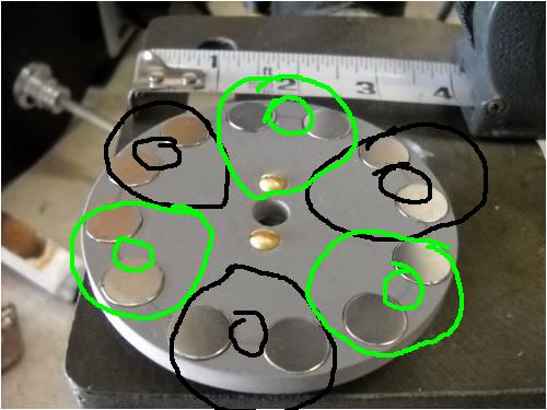
sorry ignore the colours each coil is in series with the next
Edited by niall1 2010-07-08
niall |
| |
oztules

Guru

Joined: 26/07/2007
Location: AustraliaPosts: 1686 |
| Posted: 12:29am 07 Jul 2010 |
 Copy link to clipboard Copy link to clipboard |
 Print this post |
|
It will need all the efficiency it can get, and the vibration with single phase may shake it to bits.
.....oztules
Village idiot...or... just another hack out of his depth |
| |
niall1

Senior Member

Joined: 20/11/2008
Location: IrelandPosts: 331 |
| Posted: 12:44am 07 Jul 2010 |
 Copy link to clipboard Copy link to clipboard |
 Print this post |
|
ouch.....
i kind off promise not to speak about single phase again ..  ...erm god does love all his creatures though ...at least ....i think he does.... ...erm god does love all his creatures though ...at least ....i think he does.... 
and yes ...single phase does rumble a bit (lot).... Edited by niall1 2010-07-08
niall |
| |
MacGyver

Guru

Joined: 12/05/2009
Location: United StatesPosts: 1329 |
| Posted: 01:26am 07 Jul 2010 |
 Copy link to clipboard Copy link to clipboard |
 Print this post |
|
Crew
When the smoke clears, I have decided to cull out all the "good" information and present it on the Web in a single place (PDF likely) just to keep some other well-meaning fellow from falling into all the craters I've toured.
Still in all, it's been fun for the most part so far. I'm going to take Oz's advice and wind some smaller ROUND coils to make better use of the "real estate" as he puts it. I already thought up a dandy coil winder, so I'll share that when I get around to it.
If this little 12-magnet thing is going to be good for only about 13 volts, the real one (12 magnet pairs, 24 magnets total) will likely have a hard go of it as well. I'll let you know.
Bottom line here is I like to try stuff. I'll report the findings either way, but hopefully it'll work.
I got my hands on a used car alternator today (Oz cringes) so I've got yet another toy to play with. I'm also going to build something only Oz knows about as yet (I'll share it down the road a bit; don't fret) and I'm going to use some of the 1" x 1/4" rare-earth magnets from the original 7" wheels on the ax-fx. I'm pretty sure what I've cooked up will work, but as Oz has already pointed out, it's not exactly problem free and has its own set of little peculiarities.
Such is life. Perhaps this is why most guys my age just fish, eh? 
. . . . . . Mac
Nothing difficult is ever easy!
Perhaps better stated in the words of Morgan Freeman,
"Where there is no struggle, there is no progress!"
Copeville, Texas |
| |
MacGyver

Guru

Joined: 12/05/2009
Location: United StatesPosts: 1329 |
| Posted: 04:06am 07 Jul 2010 |
 Copy link to clipboard Copy link to clipboard |
 Print this post |
|
The Saga Continues
I manufactured a new coil winder this evening after work:
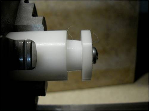
It's one piece of 1" acetal rod with a 10-24 thread running down the
middle. The end is a 'washer' I cut off after threading things. Note
how the center thimble is tapered. This lets me slide the finished
coil off the thing without having to tug.
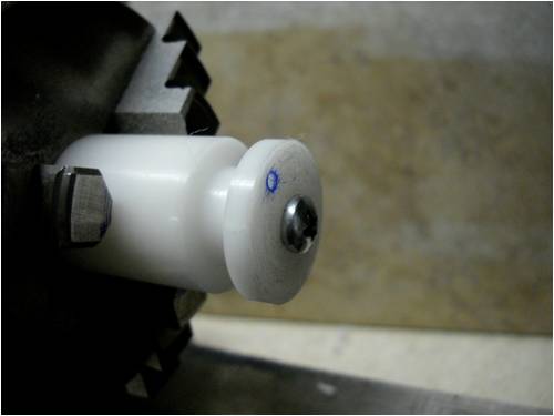
Look closely and you'll see a little "blue-ringed" hole cut into the end
washer. This lets me thread through the initial piece of wire for each
new coil. The hole holds the wire in place for the first several turns.
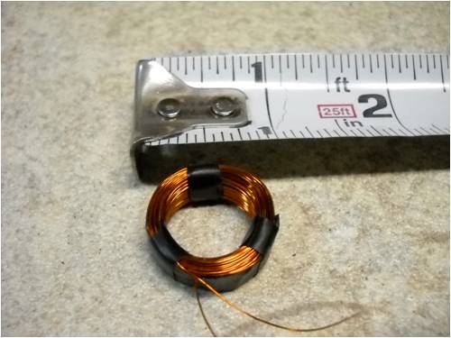
Here's a finished coil. The inside diameter is 1/2" and the outside is
just under 1". It is 1/4" thick and holds 200 turns of 30-gauge wire.
There was enough wire on one of the previous 150-turn coils to make
this one with even some left over.
I have not yet tested the coil. I had to play plumber (my profession) all day long and didn't get home until about 8 p.m. Tomorrow, I'll chuck up the 12-magnet-pair ax-fx wheels in the lathe and spin it at several known speeds to determine how much voltage one coil makes. Once I know how much electricity (a.c.) a single coil produces, it will tell me how to make the other 8 coils. There are to be 9 independent coils in the stator when it's a done deal.
I found that by cutting a 1/4" strip of electrical tape about 2 inches long, it wrapped around the coils of wire while it was still clamped inside the winding spool on the lathe. When I slid it off (it almost "jumped" off the winder peg by the way -- thanks to that taper I cut into it!) the winding peg, I held it gently and wrapped three more little 1/8" x 1" electrical tape pieces at 120-degrees around the circle to hold all the tiny wires in place so I can handle it without things coming unraveled.
I'll post the coil-test results as soon as I can take the time.
. . . . . . Mac
Nothing difficult is ever easy!
Perhaps better stated in the words of Morgan Freeman,
"Where there is no struggle, there is no progress!"
Copeville, Texas |
| |
oztules

Guru

Joined: 26/07/2007
Location: AustraliaPosts: 1686 |
| Posted: 04:10am 07 Jul 2010 |
 Copy link to clipboard Copy link to clipboard |
 Print this post |
|
Mac,
Getting the voltage you want at the revs you want is the easy part, thats only wire turns.
240v, 12v, it is all easy..... but...
Getting useable power out is a different story, and requires the best use of what you have got, as voltage without current carrying abilities is not much value.
You cant drive much with the spark from an ignition coil, but you sure have voltage 
..........oztules
Village idiot...or... just another hack out of his depth |
| |
MacGyver

Guru

Joined: 12/05/2009
Location: United StatesPosts: 1329 |
| Posted: 04:20am 07 Jul 2010 |
 Copy link to clipboard Copy link to clipboard |
 Print this post |
|
[Quote=Oztules]You cant drive much with the spark from an ignition coil, but you sure have voltage.
I know that, but I had to start somewhere and I just happened to have a roll of 30-gauge wire kicking around, so that's what I used.
I imagine anything worth having will be in the neighborhood of 16 to 14 gauge wire as far as current-carrying ability goes, but i didn't want to spend lots of $ on spools of wire right out of the gate and decided to go with what I had on hand. I'll fine tune this thing as I clean it up. For now, I'm still taking 'baby steps'. 
. . . . . . Mac
Nothing difficult is ever easy!
Perhaps better stated in the words of Morgan Freeman,
"Where there is no struggle, there is no progress!"
Copeville, Texas |
| |
Downwind

Guru

Joined: 09/09/2009
Location: AustraliaPosts: 2333 |
| Posted: 04:52am 07 Jul 2010 |
 Copy link to clipboard Copy link to clipboard |
 Print this post |
|
Mac,
As Oz said earlier you dont need to buy a different wire size you just wind two or three strands in hand.
This means you wind 2 or 3 strands of wire together in parallel.
It is like running 2 water pipes next to each other to double the flow (as you like a plumbing answer)
Once wound then join the strands together on each end.
Think of it as, 2x 1" pipes = a 2" pipe. so 2x 0.5mm wires = 1x1mm wire.
The bigger the size copper wire (or total of) the greater the Amps output for the same amount of turns.
As Oz quoted you need to workout how many turns are needed, then fill the "Real Estate" you have, with as much copper wire as you can get in, with maintaining the number of turns needed.
If its 50 turns you need, then wind as many strands of wire as you can possiable fit in for the area avaliable for each coil.
At your present rate you will end up with lots of short length of wire all wound into little coils but not much good, other than using them to rewind into another coil for 2 or more in hand.
Pete.
Sometimes it just works |
| |
MacGyver

Guru

Joined: 12/05/2009
Location: United StatesPosts: 1329 |
| Posted: 05:02am 07 Jul 2010 |
 Copy link to clipboard Copy link to clipboard |
 Print this post |
|
Pete
Thanks for that. You see, all along I've kinda wondered what "in hand" meant. Now I understand. It makes perfectly good sense both from an electrical as well as a plumbing point of view.
I'm going to see what I get with the 200-wind coil I made this evening gust for kicks & giggles anyway. I already took the time to build it; may as well test it, eh?
I still think a basic terminology section would be well worth the time it would take to build and post here on the 4m. This is a perfect example. "In hand" may be somewhat of a colloquialism but for someone not of the same region, it's Greek! Then again, maybe I'm just thick; thick headed -- the rest of me is getting pretty fit of late! 
. . . . . . Mac
Nothing difficult is ever easy!
Perhaps better stated in the words of Morgan Freeman,
"Where there is no struggle, there is no progress!"
Copeville, Texas |
| |
| |
  Page 4 of 6 Page 4 of 6   |

