
|

|
Forum Index : Electronics : Nanoverter and Backfeeding with a GTI
| Author | Message | ||||
Madness Guru Joined: 08/10/2011 Location: AustraliaPosts: 2498 |
Here is the cause of my problems. 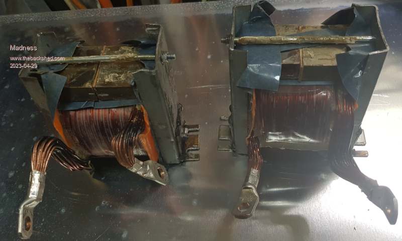 With both of these fitted the inverter works fine just as an inverter making AC power. They might look small but they weigh about 10KG each. The GTIs don't like them, with 2 smaller chokes I get this sine wave. 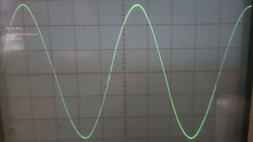 This is with just one GTI connected back feeding 500W with no AC loads. The offending chokes are made with 2 of the large aerosharp choke cores joined together and 12 turns of 31 1.6 diameter wire. My inductor meter may be wrong but it shows 80mH. The chokes that are working are 2 of the small aerosharp chokes joined together with 6.5 turns. I can't run it hard with these as the wire in them is only about 10mm square. The next step is to remove the windings from the 2 big chokes and try different numbers of turns of temporary wire. When I find what works I wind them again with enamel wire, it will be a lot fewer turns so I will be able to get a much larger wire cross-section. This is the Nano 1 code used if anyone wants to try it. It is the same as the file Poida upload just with this line u = 32000.0 * sin(t); changed from 20000 to 32000. If you are not wanting to back feed then you are best to stay with the Nano 1 versions Poida. nano_1_2_X_SINE_Mad_Fix.zip Edited 2023-04-29 15:05 by Madness There are only 10 types of people in the world: those who understand binary, and those who don't. |
||||
| Murphy's friend Guru Joined: 04/10/2019 Location: AustraliaPosts: 648 |
If its any help, the choke on the right is what I'm using in my dual stack nano inverter: 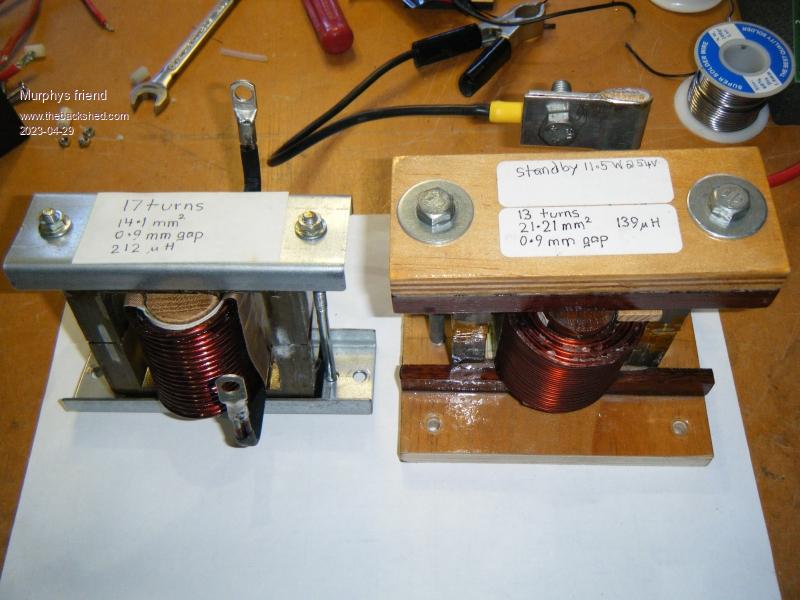 |
||||
Madness Guru Joined: 08/10/2011 Location: AustraliaPosts: 2498 |
It would be interesting to see how your inverter goes back feeding with the code above. What is the core of the choke you are using? There are only 10 types of people in the world: those who understand binary, and those who don't. |
||||
| KeepIS Guru Joined: 13/10/2014 Location: AustraliaPosts: 1679 |
I might be having a seniors moment so ignore me if not relevant, but the choke values appear to be a tad high to me. I found that anything above a total of 75 MicroHenrys for one choke, or around 36uh each for dual chokes, can start to cause instability under complex loads and an even greater chance of ringing and resonance in the testing I did, especially the 3 stack toriod transformer, less so with the single Aerosharp, but it was still there. Obviously there is complex interplay between 3 major components. I guess some builders haven't seen this on their DSO in testing. But I can't help feeling that somewhere in the background there is a problem just waiting to happen with the right (wrong) load conditions and high inductance chokes. Maybe I'm misunderstanding something here, or perhaps I'm the only one who noticed that. . Edited 2023-04-29 19:12 by KeepIS It's all too hard. Mike. |
||||
| poida Guru Joined: 02/02/2017 Location: AustraliaPosts: 1418 |
KeepIS, I think you are on to something there. I wonder what the resonant frequency of the primary is, with these large inductance chokes in Madness's situation. wronger than a phone book full of wrong phone numbers |
||||
| Murphy's friend Guru Joined: 04/10/2019 Location: AustraliaPosts: 648 |
Large aerosharp choke x 2 made into an E core. |
||||
| Murphy's friend Guru Joined: 04/10/2019 Location: AustraliaPosts: 648 |
Easily changed by fitting a bigger gap spacer. Actually, that inverter is in pieces at the moment so I will try your suggestion. Choke function has been - is- mostly a mystery to me so I'm still experimenting. What I did find was that ferrite core chokes did not do well at all in my opto isolated nano inverters. |
||||
| mab1 Senior Member Joined: 10/02/2015 Location: United KingdomPosts: 209 |
Just to be sure i'm on the same page as everyone else:- I assume that's a typo? you meant 80uH not 80mH? otherwise that is high! building the choke is one of the things that still daunts me a bit - reading other peoples builds, it seems to be somewhere between pot luck and a black art to get one that works well. |
||||
| nickskethisniks Guru Joined: 17/10/2017 Location: BelgiumPosts: 458 |
Yes I think that will be a typo (or as Madness says, a malfunctioning meter):p Madness, I hope we are not polluting your topic, otherwise feel free to say if we do. But it's nice to have a little discussing so hopefully we can gain some more insides in this incredible world of inverters. Like KeepIs says, I'm also not having great results with higher inductance values. I keep 50uH as a rough guide. A to high inductance will mess up the regulation and indeed mess up the stability. I think Peter is in a better position to add some comment on this. He designed the nanoverter software based on his system (inverter). There will be some margins we can explore but these are not defined. We are all using different components, for sure this has it's consequences. You might find this a rather slow video, but the creator is explaning an LC-filter calculation, there are 2 formula's involved to calculate the inductor and capacitor value in a pwm inverter. https://www.youtube.com/watch?v=ypvdxe0Eecs&t=309s We are putting the filter capacitor on the output so we can get away with a factor (transformer ratio?) smaller. I've seen/read better explained LC filter designs but one thing I see coming back is they use at least 10 times the output frequency for the filtercapacitor calculation, to avoid resonance. Edited 2023-04-30 06:52 by nickskethisniks |
||||
| KeepIS Guru Joined: 13/10/2014 Location: AustraliaPosts: 1679 |
Madness said 80mH and I took that as MicroHenry. But he has two for a total of 160 MicroHenry. I fell that could cause strange glitches in the primary waveforms under certian loads, it did in all testing I carried out, but it took a while to catch it as it only occurs with some complex loads under both high and low power. I find the choke design a bit simpler now: 1: Enough inductance to protect/reduce FET switching current at Idle. 2: Enough Inductance to help filter some 20-25kHz noise in conjunction with the Transformer LC filter (Toriod and secondary CAP). 3: Some inductance left under High current (not fully saturated). I regularly see short term Peak DC inputs power approaching 25kW in my inverter. Apology if getting off topic. . Edited 2023-04-30 07:58 by KeepIS It's all too hard. Mike. |
||||
Madness Guru Joined: 08/10/2011 Location: AustraliaPosts: 2498 |
@nickskethisniks If it is vaguely on topic then post away. @KeeoIS You are not off-topic, I did establish yesterday and posted that there is too much inductance, so discussing inductance is very much on topic. @Mab1 Over the past few months I have done a lot of reading on here before building this new inverter to get myself back up to speed as it has been around 5 years since I built any inverters. I was under the impression from what I read that the higher value inductor you have the better, clearly that is not the case. What I have done is remove the windings from the choke cores. This was quite easy as the windings were wound onto a close-fitting 3D-printed former. I had some 95mm square battery cables on hand that I have wound on the cores with 3 turns on to the double large Aerosharp cores. My meter says 0.01mH, so my previous post should have been 0.08mH. 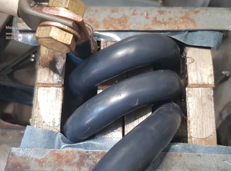 I have 2 of these one on each side of the toroid primary. This is working right now with 2KW back-feeding and no load on the inverter. It is running with a near perfect sine wave. There is no sign of any glitching, disconnections or any other gremlins. 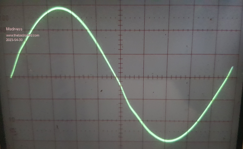 The inverter is run near silent, I don't have any filters on the AC out. There is a very slight trace of the 20khz switching that I will ignore. 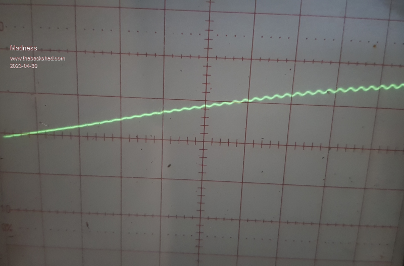 I will let it run for most of the day and if all is well I will reassemble the inverter properly and then I can test it under full back-feeding load. ATM I am thinking I have succeeded in what I set out to do here, which is to get a Nanoverter back-feeding successfully. Edited 2023-04-30 10:08 by Madness There are only 10 types of people in the world: those who understand binary, and those who don't. |
||||
| wiseguy Guru Joined: 21/06/2018 Location: AustraliaPosts: 1156 |
When I first started designing my inverter ~3 + years ago my calculated value was ~ 47uH. When I made my first inverter I used ~90uH working from Warps statement that more uH is fine and it just reduces the chokes P-P ripple. My own theory was that more series inductance will lead to less peak current during the on time and that eventually energy throughput would suffer. Whilst trying to find the reason behind the grunt on startup with my inverter I tried a different choke with a few less turns and the grunt was much quieter, I have not returned to the issue in depth yet to fine tune the choke, as I'm working on other projects I want to finish before an imminent long holiday. But Mike's (KeepIS) fine tuning supports a similar result. I think 10uH is too small and the FETs will be seeing quite large current peaks due to saturating effects and that is why you now see the 20kHz superimposed on the 50Hz fundamental. I think that a value somewhere between 30 - 50uH would be kinder to your mosfets. Whether this will help with the GTI back-feeding issue or not is anyones guess. If at first you dont succeed, I suggest you avoid sky diving.... Cheers Mike |
||||
Madness Guru Joined: 08/10/2011 Location: AustraliaPosts: 2498 |
The inverter that has been running my house for the last 6.5 years has the original Oztules Ferrite choke which is a lot lower value. The actual value of the chokes I am using now may be quite different to what's shown on the meter I have used due to its dubious accuracy. The MOSFETs seem to handle that year in and year out running 24/7/365/6.5. This inverter can run at 8kw for at least 30 minutes and does work everyday. It is not unusual to see it making 6kw for extended periods every day when my wife is cooking. Quite often the oven and induction cooktop and air fryer are running plus the house water pump starts and stops every time a tap is turned on. During the day the same inverter spends many hours back feeding 5-6kw from GTIs. While I appreciate your input, is the tiny bit of ripple really an issue? Based on the experience I have had and the fact that I need the back feeding to work I won't be aiming to put more henries in the chokes unless I see smoke come out. As for grunt at startup, this inverter is so quiet you would need to put your ear on the case to hear it at start up and it has got a very big toroid. It scares me a little that is so quiet I don't know it is running. The toroid is so heavy I could only just lift it, if it had another core I would literally need a block and tackle to lift it. Just before I saw it back feeding 2.5kw, there is a small hum like you get from large grid transformers but it can barely be heard. My old inverter buzzes and makes all sorts of noises from the choke, I can tell just from the sound what is running. It has been running perfectly for about 4 hours now, the toroid is up to 28 degrees and the heatsink has got to 41. I connected a fan that is set to start at 41 and stop at 39. It comes on about every 15 minutes for a couple minutes. I am very happy with how it is running. There are only 10 types of people in the world: those who understand binary, and those who don't. |
||||
| wiseguy Guru Joined: 21/06/2018 Location: AustraliaPosts: 1156 |
What value of mains capacitor are you using? Can you estimate the P-P ripple you see on the 50Hz waveform? Have you ever noticed the 20kHz ripple previously? It is not so much the voltage ripple that can be seen but more the 20kHz current involved that is causing it. I am not questioning the longevity or reliability of what was, maybe I misunderstood but you are now using 10uH which is a very low value If at first you dont succeed, I suggest you avoid sky diving.... Cheers Mike |
||||
| KeepIS Guru Joined: 13/10/2014 Location: AustraliaPosts: 1679 |
Hi Mike, I believe Madness is running two chokes, so 20uH and no AC filter. But on your point about 20kHz and other HF currents. Back a while, I was interested in actually seeing this and not being fooled by the DSO and common mode noise / current on the leads when measuring it. So, I put a small jump lead across the 35uH on the LO side, the jump lead got hot straight away at low power and can start to melt at higher power. That clip lead is across 4 turns of very Heavy cable. The HF energy taken out by the choke, even on the LO side is substantial. The Waveform across my primary terminals is a really clean sine wave. BTW, shorting the choke changes the power factor on my inverter AC output meter, but only on when shorting the LO side choke. It's all too hard. Mike. |
||||
| wiseguy Guru Joined: 21/06/2018 Location: AustraliaPosts: 1156 |
Hi Mike, I did miss Mads photo caption saying, "I have 2 of these".... I am pretty sure Mad has an AC capacitor on the transformer secondary but no extra filter afterwards. Without any AC capacitor fitted to the mains winding my inverters output is about 98% less. I do get the "if it aint broke dont fix it" motto, but sometimes you can get a hint that broke could be coming. BTW even in an inverter just idling, there can still be many Amps of circulating currents going on, but these are essentially re-circulating and are not used or lost. If at first you dont succeed, I suggest you avoid sky diving.... Cheers Mike |
||||
Madness Guru Joined: 08/10/2011 Location: AustraliaPosts: 2498 |
Yes, there are 2 chokes and I have 2 aerosharp 10J300300VAC capacitors across the toroid secondary. My meter says 4.6uF each and they are in parallel. I checked the resonance and it is was around 78hz with the previous chokes fitted. 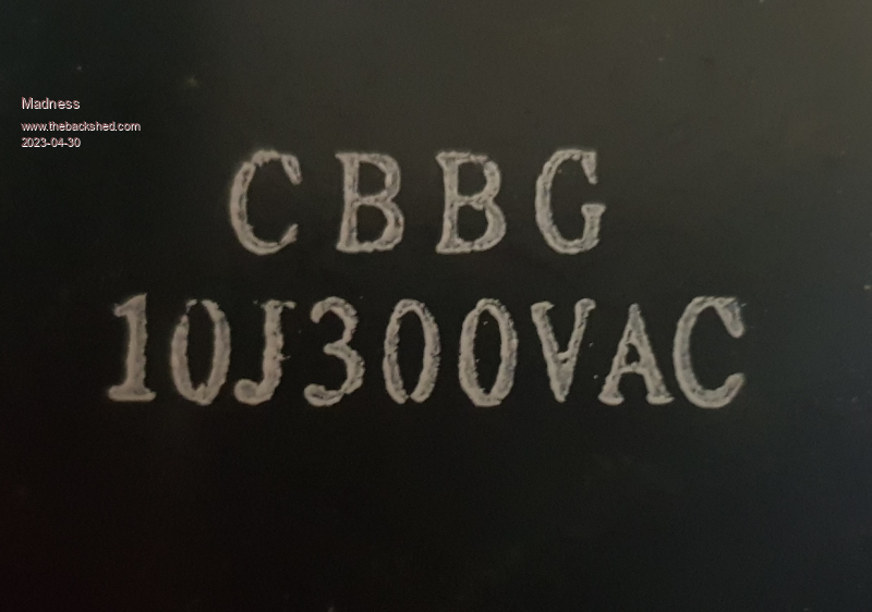 The 20khz ripple is less than 5V, the transformer is 1:9 so this would be under 0.5 volt on the primary. Each line is 50V. 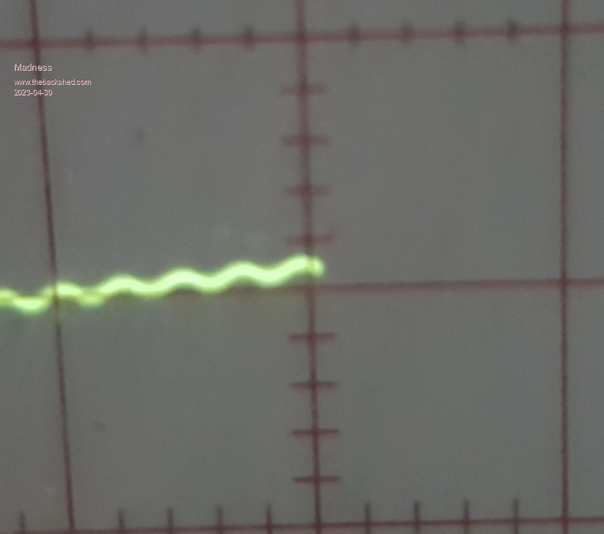 I checked old faithful and the ripple was a bit more than double this, it has filters on the output and as mentioned this new inverter has no filters at all. Edited 2023-04-30 18:25 by Madness There are only 10 types of people in the world: those who understand binary, and those who don't. |
||||
| Murphy's friend Guru Joined: 04/10/2019 Location: AustraliaPosts: 648 |
Its all very confusing but remember, there are TWO types of inverters being built here. One uses 20KHz and 50Hz inputs to the transformer primary. The other (nano) inverter uses, according to its creator Poida, 2 x 100Hz at the primaries. So I think that does make a difference regarding the ideal chokes. KeepIS has got the 20KHz/50Hz type perfect with his chokes. I'm not quite there yet with my 2 x 100Hz nano inverter type. It works but there is room for improvement with the wave form at various loads. |
||||
Madness Guru Joined: 08/10/2011 Location: AustraliaPosts: 2498 |
The Nanos PWM is working at 20khz, the 100hz is each half cycle of the sine-wave. So on one half of the sine-wave on the code you are using the inverter is switching on and off the 2 positive gates at 20khz. Then the negative gates are working at 20khz to form the other half of the sine wave. So there are 2 halves to make 1 full cycle of sine @ 50hz, the 100hz is the 50hz divided by 2 for each half of one sine-wave. Within that, the MOSFETs are switching on and off at 20khz, the period that they are on determines the amplitude of the sine-wave at that point. Just to confuse things a little more, the 2 X sine as Poida calls it or bipolar is switching on positive and negative at the same time. If you watch this video it explains it really well https://www.youtube.com/watch?v=vOtamo-Vpvw it shows Bipolar which I am using now and unipolar which is what is running in your inverter. I have reassembled my inverter with the new choke configuration after running most of the day very successfully with the power board outside the inverter and the chokes half in and half out like it had been disembowelled. I will switch the house and GTIs over to it first thing in the morning and see if it runs as well as it did today. Tomorrow I will see how it goes with loads but I am very happy with the wave-form as it is, Klaus it would be well worth giving the code from here a try. You can load it onto another Nano and just swap the Nano with the one you have installed now. Then you can easily change back anytime if want to. From my experience it might be well worthwhile taking a look at your chokes too. Edited 2023-04-30 19:39 by Madness There are only 10 types of people in the world: those who understand binary, and those who don't. |
||||
| Murphy's friend Guru Joined: 04/10/2019 Location: AustraliaPosts: 648 |
Thanks for that explanation Gary, my confusion comes from when I asked in another thread which is the high side and which is the low side I was told they are both the same switching at 100Hz. Anyway, a choke at each primary end should sort it no matter how it works  . .Programming nanos is something that I try to avoid at my age, there's a very good chance to stuff it up. I will change the big choke's inductance to match the 40uH of the powdered iron toroidal choke on the other primary side. We'll see what that does, it will be a few days before I get to test that. |
||||