
|

|
Forum Index : Electronics : all home built solar system
| Author | Message | ||||
| Warpspeed Guru Joined: 09/08/2007 Location: AustraliaPosts: 4406 |
All this makes perfect sense for a boat where there is going to be very limited space available for either batteries or solar panels. Fully sealed batteries will be a pretty important requirement too, so a very compact and efficient system should be possible. This might also apply to something like a camper van for similar reasons. A domestic off grid system where there is usually vastly more space, and size and weight of the battery much less important, my own personal belief now, after being bitterly disappointed with lithium reliability, is that an excess of low cost used solar panels, hooked up to a vastly oversized fork lift battery will probably provide best bank for my buck overall. The main argument for a lithium/lead combination seems to be the capacity for very high short term charge and discharge rates. A higher voltage system runs at lower current anyway, and if the lead acid battery size is very large, sudden surge loads are going to be much less of a problem. My next attempt at this will probably be two 48v fork lift batteries in series. Going on Marks voltages 115v down to 100v would be ideal for my 90v to 180v inverter. I should get far more amp hours per dollar, and the batteries be far more tolerant and reliable. Cheers, Tony. |
||||
| Solar Mike Guru Joined: 08/02/2015 Location: New ZealandPosts: 1138 |
Tony I was talking to a battery engineering person awhile ago about using forklift batteries in a home solar setup, he advised against it because their electrolyte specific gravity is higher than normal LA batteries and thus the plates will wear out faster, he said they are really designed for high usage and full charge on a daily or twice daily basis; they are not designed to last a long time. How true that advice is I don't know, he was the expert. Cheers Mike |
||||
renewableMark Guru Joined: 09/12/2017 Location: AustraliaPosts: 1678 |
My century battery was the same as a normal FLA. The guy at the fork place I got it from told me to add more acid to get more performance out of it or leave it as is to make it last longer. I think you'll find cheapie brands put more acid in to get the performance up. Cheers Caveman Mark Off grid eastern Melb |
||||
| Warpspeed Guru Joined: 09/08/2007 Location: AustraliaPosts: 4406 |
My understanding of fork lift batteries is that the chemistry is almost the same if not identical, but they are built to be very mechanically rugged. Fork lifts generally have very hard solid wheels and no suspension springs. So if you drive over the smallest bump, the batteries get a real shakeup. Lead is about the worst material to build anything out of that must be both stiff and strong. I don't know about the specific gravity of the electrolyte situation, but it would not surprise me if there were variations for different applications. The lead acid batteries in telephone exchanges typically easily last 50+ years but they are maintained by experts and given tender loving care. Fork lift batteries do get a real thrashing though, both mechanically and electrically. The battery chargers are really crude, and the young minimum wage low IQ fork lift drivers, really give the machinery a hammering too during their shift. I would think any fork lift battery would be very grateful to retire as a solar battery. If its big enough the daily depth of discharge should be minimal. But they probably should be fast charged and equalized to a higher voltage occasionally. A good gassing every few months will clean the plates, and like people, a bit of serious exercise occasionally, is good for your overall health. Cheers, Tony. |
||||
| nickskethisniks Guru Joined: 17/10/2017 Location: BelgiumPosts: 458 |
Hi, I'm combining (hard parallel) AGM and lifepo4 for years now and I'm very happy with the combination I do agree on most of what he is saying but not all. Explanation of solar Mark says it all, I think I use the same values but some longer timings. I think I keep 11.8V (20% agm), (I'm using powersafe telecom and traction agm) soc for my system, that way the LA are protected, last winter I ran the generator each time my system went below 50V. The LA are protecting my lifepo4 against deep discharging, it's difficult to estimate their soc. The lithium are taking the highest charging/discharging chunck due to low internal R and flat voltage curve. So lead acid are little bit babied and working efficiently. It's only in the winter they are getting their work out. LA loses capacity when heavy loaded, you can compensate that with oversizing or adding lifepo4, but when the lifepo4 get at the "knee" the LA are taking over. You can't charge LA very fast, but that's maybe not a real disadvantage in stationary storage. I think their are better regimes for the LA, but for the combination this is the simplest method. I think Warpspeed recommended me to do a complete charge and let the LA battery rest afterwards, instead of the float regime. That's also an option, like in periods the battery is not used at all and is acting like a fifth wheel, summer for example. Maybe that's better and is better in avoiding sulfation? For designing the setup, I would sugest to get 3 times the maximum charging rate for the lithium battery. For instance if you can charge with 100A, I recommend a 300Ah battery. When testing small batteries I notice a limited heat production at that rate. Sure you can charge at 1C but I wouldn't do that for degration reason's, heat is one of the main concerns when aiming for long life. I like my lifepo4 very much but if you can lay down enough cheap solar panels and can buy LA (quality) at say 1/2 the cost of lithium I would choose that route. I'm always expanding my system with what I can find at a good price. This year I bought 18kWh Valence lifepo4 cells for about 1100eu ( downside, it will cost me a LOT of time to make bricks out of it). I bought them because those were almost new and my current Valence setup is from 2006 and doing well, still no unexpected failures. I still can't understand why people had failures with Winston cells, in my eyes they are (were) the rolls-roys of lifepo4 bricks. And 2y ago I bought those new 12V 58Ah xfc traction agm for 40eu/pcs, those were very fast chargeable and you could charge them up whenever you wanted. I want to aim for 100kWh, just for the number alone. But for now I just want to beat the degration in my system, it's staying a hobby not to make profit. Edited 2021-04-25 01:56 by nickskethisniks |
||||
| poida Guru Joined: 02/02/2017 Location: AustraliaPosts: 1418 |
I want to show the Gate voltages for the new board. I am very happy how they look, and they appear quite similar to those on the Madness 6kW power board. This no surprise. Purple is low side Gate drive voltage Dark Blue is high side Gate voltage 50V input, 200W load 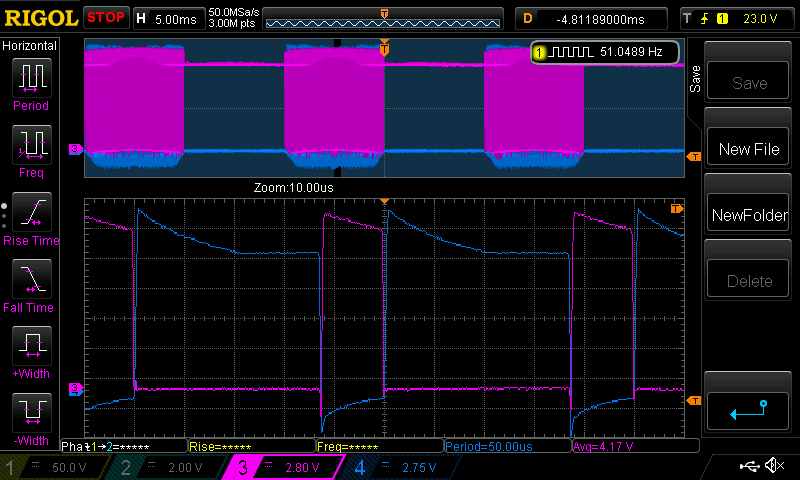 and close-ups of the Off and On switching of the half bridge Off: 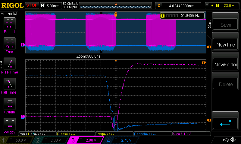 On: 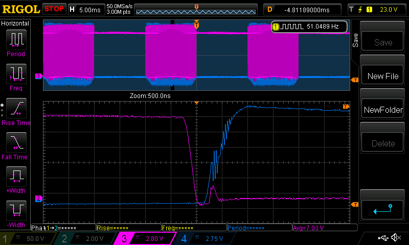 This is perfectly acceptable and no doubt this clean Gate drive is what permits the power board to survive 11kW with 3 x 4 FETs The droping voltage over time is present in the Madness power board as well as mine. I see no problem at all with this. The FETs are fully switched ON during the period where the voltage drops. When the HY4008 is fully switched on, the Rds(on) resistance is 2.9 mOhm The HY4008 specs show Rds(on) resistance is already 3.0 mOhm at 7V We can see minimum Gate voltages of about 12.3V or a bit more so there is a large margin of safety here. Very pleased to see this. wronger than a phone book full of wrong phone numbers |
||||
| Haxby Guru Joined: 07/07/2008 Location: AustraliaPosts: 423 |
The way I read it, the high side gate is bouncing a few times in the conducting region. Isn't that a bad thing? 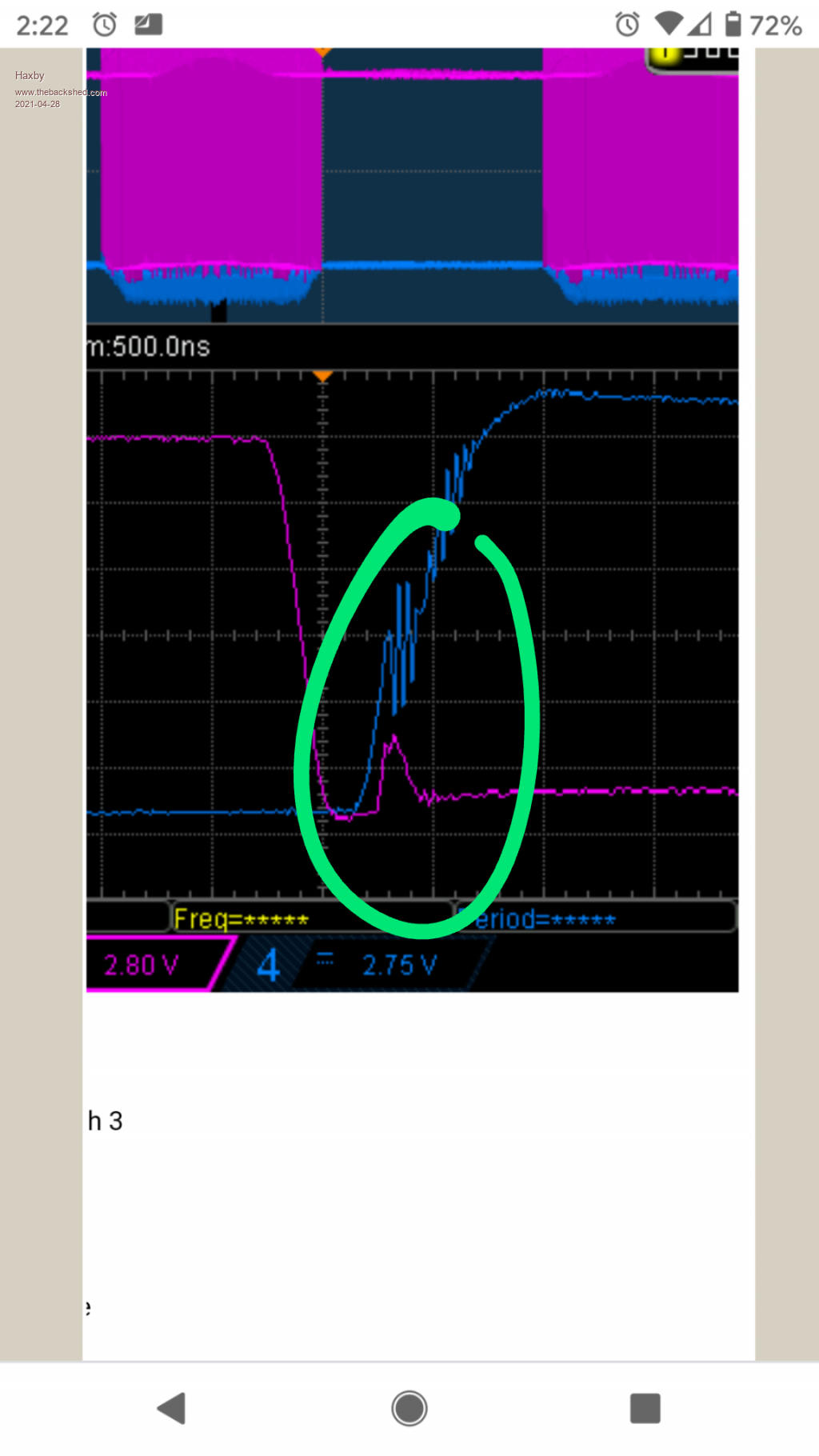 |
||||
| poida Guru Joined: 02/02/2017 Location: AustraliaPosts: 1418 |
Haxby, that part of the switch on means the high side is being pulled up to DC. This rapid change in the low side Drain pin means the capacative coupling will cause the Gate to rise, as we can see in the Purple bump. It's probable that the low side FET is conducting a bit, now and then, driven towards some natural frequency. It's normal and expected and it does not lead to destruction (your mileage may vary, etc.) I have trialed ferrite beads on a few of the pins but not much is gained in my experience. It might be good to slow down the natural frequency of the high side Source/Low side Drain node in some way. wronger than a phone book full of wrong phone numbers |
||||
| shallowal Regular Member Joined: 26/07/2018 Location: AustraliaPosts: 58 |
Peter, I notice a difference between your totem pole configuration and Mads initial version that's used on the 8Kw boards. You have the 20 ohm series resistor, but no 10K pull down resistor in the base drive of the totem pair. Is there a reason for this?. I thought it would be important to have a failsafe OFF status if for example the powerboard has power applied, but no control board connected. This could mean that the totem Bases drift high and switch on the FETs. Allan  Allan Allan |
||||
| Davo99 Guru Joined: 03/06/2019 Location: AustraliaPosts: 1578 |
I have looked into the Fork batteries quite a lot and looking at the manufacturers recommendation and warranty terms is interesting. One thing with fork batteries is they are subject to far higher discharge rates than would be applied in the great majority of the time than their designed use which can pull many Hundreds of amps. Moving the things up a ramp while loaded and running the pump to raise the mast at the same time pulls many hundreds of amps and that is just not going to happen with near the frequency if at all in a home setup. The first thing I noticed looking at the manufacturers sites is they are warranted for 5 Years to 80% DOD. Many people assume they are 20% or 50% but for fork batteries, that's simply not true. There are also notes that less DOD will result in longer life which goes with every other general knowledge. People using Fork Batteries report having them in excess of 10 Years, many claiming 15. I did notice that they are also rated for one cycle per day. A cycle is pretty much any discharge and recharge. They suggested that not recharging if above 30 % DOD would be preferable. The chargers do tend to be Crude, Full amps and the final charge before going into float. A gentler and more progressive charge rate would no doubt be a lot kinder and aid to the longevity. I spoke to a couple I know that live off grid a week ago about their setup. Turns out they are using fork type batteries although they knew of them as traction batteries but seeing a picture, they are the exact same design only they don't have them in the steel containers fork packs are normally housed in. I thought from what they had told me before they were more like gold cart batteries but not the case. They are the tall type of very high AH per cell. They have had them 14 years now and top the water up in the watering system every 3 months or so and have a guy come out and check the system. Apparently cleans terminals and connections and not much more. They have a small farm which they were doing dairy but have given that away since the gentleman turned 80 and are now just doing silage. They are very happy with their setup and although they only have 2 Kw of panels, said the only time they run the generator is for welding and other heavy loads the inverters weren't set up for. Something the Lipo proponents espouse in their advantage over LA is charging rate. No question Lipo can handle higher charge rates than LA but when you look at a typical fork pack of around 30KWH, Through sheer size, one is going to be able to pump in all the amps and more any reasonable ( large) solar system could generate anyway. I think I put the numbers up here or else where a while back but from memory a 48v, 600Ah pack could take around 120A Charge or about 6.5 KW. That's not pushing the things, that's what they will handle comfortably. If you have only taken say 30% out of the things, it's not going to take long to charge them IF you have the power even at their final charge rate. I'm not saying Lipo are not superior in a number of ways to LA but looking at the Home power/ off grid applications, pretty much all those advantages are irrelevant. Size and weight is not an issue for stationary use, on a fork pack discharge and charge rates are more than one could need... Not sure what the downside is. They certainly beat the pants off Lipo for cost that's for sure. The other advantage I have pointed out before was after doing a ring around maybe a year ago now, I found the Fork batteries were worth 25-33% of their cost price. That's basicaly a discount off their purchase price straight up. At this point there is no scrap value in Lipo and only one place in Oz in WA gearing up to recycle them anyway. Long way to send cells from the east coast where the population is. There is endless talk about lipo getting cheaper, fact does not bear that out. Just the other week I saw Market reports about the price of lithium going up due to predicted severe shortages caused by the demand from the EV market. Nothg gets cheaper when there is High demand and shortage of supply of raw materials. Going to be a long time if ever they get cheaper. Many of the lipo proponents claim longer life over LA but I don't believe that is either proven nor assumed on a fair basis. Most claim LA has a life of 5 years which is simply not backed up in practice. While lipo has been around for some time now, Those with 10 Yo batteries are not the same as one would get now. With all the different flavours of lipo, I think at this stage its a stretch to make any long term claims as to their longevity. LA has been around for decades basically unchanged and there are endless instances of them lasting 10 -20 years. Fork batteries are certainly a lot bigger and heavier than Lipo but for my money also, that's where the best bang for the buck is by far at this point in time.. |
||||
| Warpspeed Guru Joined: 09/08/2007 Location: AustraliaPosts: 4406 |
The thing about fork lift batteries is that they must last a full busy eight our working shift. Its no good if you are loading big trucks all day, and the fork lift starts to really slow down by the middle of the afternoon. So a lot of batteries that may only be a few years old may not be up to the really heavy task of full commercial fork lift operation, and get junked. These batteries would be ideal for us at a considerable saving on the cost of brand new batteries. I think properly refurbished batteries that come with a guarantee might be a pretty safe bet. Just buying really old batteries without knowing their history and without any guarantee might be an expensive mistake, so I think we may need to be a little bit cautious about what we buy and who we buy from. Cheers, Tony. |
||||
| nickskethisniks Guru Joined: 17/10/2017 Location: BelgiumPosts: 458 |
Hi Peter, I recognize this as oscillation in the miller plateau. When I tested a lot of MOSFETs and igbt's I had results like this, 1 way to improve this is adding some gate capacitance and fine-tuning the gate resistor. The results differ from device to device, ixys MOSFETs came out best, the huy4008 was better then most IRF MOSFETs. There was no 1 fits all solution for this. Don't know how you measured, by know you use probably the best techniques. But I noticed if I measured at the legs of the fet itself, just before they enter the package.(best results) It gave very other results then measuring on the legs more near the PCB. (Worst results) So things could actually be better then how it is presented now. This was the first explanation I came a cross, it's not long to read, there are better documents describing this fenomenom/solution but I need to look for it. They discribe igbt's but it's true for MOSFETs as well. miller plateau This is a copy of other available pcb's so I'm sure things could be improved by simple improvements. Component placement and track length/symmetry could probably be improved. I want to improve my knowledge on this, I think that a HF course would help for this kind of things, but time... Edited 2021-04-29 12:28 by nickskethisniks |
||||
| poida Guru Joined: 02/02/2017 Location: AustraliaPosts: 1418 |
Gee it's great when someone reviews your work and picks up potential issues. I will include them in the next and likely final version. Thanks heaps Allan wronger than a phone book full of wrong phone numbers |
||||
| poida Guru Joined: 02/02/2017 Location: AustraliaPosts: 1418 |
thanks for the comments Nicks, the pdf was particularly good. I do not see much value in perfecting the board. I just want it work well enough. These oscillations can be produced by increasing the load or power and if we want to examine this issue, then tests will need to be made at a few widely spaced output power level test points. And consistent test conditions.It could be done. The pdf shows how adding capacitance accros the gate/source pins can help. That was never on my list of possible things to try. I will have to try this now. 1 to 10nf caps, and now we can start to assert control with some RC (actually RCL) dampening. wronger than a phone book full of wrong phone numbers |
||||
| poida Guru Joined: 02/02/2017 Location: AustraliaPosts: 1418 |
As far as a future battery purchase: I am 100% decided that a reconditioned fork lift battery will be best for me. It will have bolted terminal connections. And come with a decent warranty. I noted well the fact you could tune up these with stronger acid concentrations to cheat a bit more performance. That is to be avoided. I just need to use up the present battery before scrapping and replacement. My battery has lost some of it's capacity. Last week I tested it and could obtain 15kW.hr from it. Just. It is rated at 400Ah and the nominal 48V when discharged at C100 At C10, it's 330Ah I discharged at somewhere in the middle of this, more towards C100. So the battery is not stuffed. It is showing it's age and I think I have used charge settings that accelerated it's decline (one volt or more too high float charge voltage. As always I value everyone's comments and read them all. wronger than a phone book full of wrong phone numbers |
||||
| Warpspeed Guru Joined: 09/08/2007 Location: AustraliaPosts: 4406 |
Nick is quite right about the tendency towards oscillation. Its basically ringing due to parasitic inductances and capacitances due to very steep changes in current, and it can be reinforced by any drain gate coupling while passing through the linear region. No hard and fast rules to fixing it, as its dependent on physical layout as much as anything else. Loading it with capacitance can introduce phase shifts and move resonances around, and sometimes influence any unfortunate mutual coupling, but the best initial approach to this is usually to try to kill the Q of whatever is resonantly ringing. Damping resistors of surprisingly low resistance can be effective at lower frequencies, and ferrite beads at higher frequencies. All this is more luck and trial and error than an exact science, but sudden bursts of RF can be a major source of EMI, as well as just looking ugly on an oscilloscope. Cheers, Tony. |
||||
| Davo99 Guru Joined: 03/06/2019 Location: AustraliaPosts: 1578 |
I'd not heard of hotting up the batteries with more acid but I wonder if this technique could be used to get some extra life out of the declining pack? Where it might be falling off with the regular electrolyte concentration, something a little stronger may restore some extra capacity Perhaps? My uneducated guess would be if the battery performance improved, it's ultimate decline would probably be akin to dropping off a cliff. What size Fork pack are you thinking of? 620 AH, 48V seems to be a common size. with around 30 Ah capacity, certainly would allow for a good reserve whilst still maintaining a low DOD. When used through the day, once charged, anything drawn from them should be in effect coming from the panels? Charger so the batteries should see no discharge at all. With a decent west facing array, one should be able to go into the evenings on any sunny day with fully charged batteries. I am surprised ( and pleased) with the generation rates I'm currently getting in Sydney for this time of year. next month is supposed to be the low point but with Very pleasant daytime temps still being the norm ( much to my surprise) shouldn't be hard to keep up with consumption as long as this holds out. From what I have seen, the forklift places seem very happy to give warranty's On packs for solar use. I Imagine this is due to the fact they recognise it's a lot easier life on the things than their designed use. Last one I looked at gave 5 Yr warranty on their used packs as long as an auto water system was installed and the things were not discharged below 80%. Most accommodating and welcome warranty conditions I have ever read! If they will warrant them for 5 years to 80% DOD, then getting 10 years out of the things at even 50% DOD seems a very reasonable expectation. |
||||
Revlac Guru Joined: 31/12/2016 Location: AustraliaPosts: 1024 |
I think it would be a good idea to get some sort of warranty for secondhand forklift (or other) batteries, without it they would be happy to sell something for more than scrap price.... Some rough handling and or drop of the battery box, 100mm or so can crack the lead inside and there might not be any visible damage, even the voltage might test ok and light loads might still be fine, until its not, then the cell fails. I have seen many broken links in batteries, not all from rough handling, lead in not all that robust, it happens. 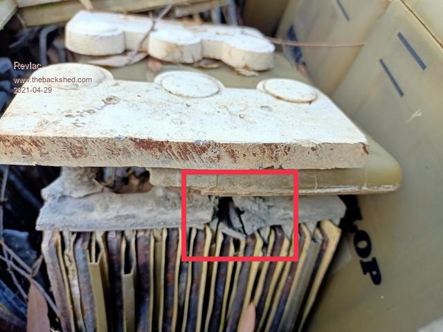 I have heard of different acid percentage in batteries, at the time it was different for hot or cold climates, might not be much of an issue with new types of FLA batteries. Cheers Aaron Off The Grid |
||||
| wiseguy Guru Joined: 21/06/2018 Location: AustraliaPosts: 1156 |
Peter, there is nothing wrong with making the board behave better (apart from time and effort involved) and I am sure it can be achieved. I do see a potential problem with releasing a design to the Forum that may cause issues due to different layouts and components etc. Whilst some of us have equipment & skills to resolve such problems others may struggle. Haxbys concern and highlight of the waveform mirrored my thoughts but I've been to busy for the last 2 days to comment. As the issue is bordering on shoot through, then the question has to be asked, how close is it to a terminal issue? In my design I chose to use a -5V bias on the lower gates during their "off" time, my reasoning was that should a gate ever be pulled up by a volt or 5 the Gate is still either below or at ground and still well below turn on. I also use 3R3 on the gates and I would suggest probably no higher than 4R7 to keep the drive impedance low. I will probe the Gate waveforms of my Inverter soon to get a comparison reference, then I will disable the -5V Bias and look again as I'm not convinced it is necessary and I'll post the waveforms I get, I don't believe I have seen (noticed?) that bump on the lower Mosfet. Whilst I have seen capacitors added to Gate/Source(Emitter?) on IGBTs to solve similar oscillation issues, I have only ever seen this technique used once with a FET to solve an EMI issue to achieve Ctick compliance. I believe adding external capacitance from Gate to Source to solve this problem is not the right or best approach. To clarify, negative bias is a technique often used in IGBTs, it is not to stop oscillation only to give better immunity to shoot through. I used it for added protection against the unknown. Most comments on the cause & implications of the trouble are correct, it is an oscillation seen on the Drain coupled back via Cgd and appearing on the gate. This is often evident and exacerbated when paralleling multiple Mosfets. I solved an identical looking issue with single Ferrite beads placed on the Drains, if the Drains are not isolated from the heatsink as per some builds this may not work effectively. Placing a bead on the gate may help in that instance. The trick is to increase the impedance at higher frequencies to lower the Q enough to become stable. Peter, I applaud the efforts you have made to date and are still making to bring an open sourced solution to the random home builder that decides to take up the challenge, knowing there is a lot of help & support available in their endeavors. Re the pull down resistor on the buffers input I would repurpose the 5K resistor that is currently on the buffer output. The separate 20K gate pulldowns for each FET are effectively all in parallel so for 4 FETs it would have ~5K to ground anyway. If at first you dont succeed, I suggest you avoid sky diving.... Cheers Mike |
||||
| nickskethisniks Guru Joined: 17/10/2017 Location: BelgiumPosts: 458 |
I saw the gate capacitor trick on a bldc controller with 3 paralleled 15810 MOSFETs (18 MOSFET total), used in a golden motor controller. With Rgate 100R and C 10nF. Reading a few topics on endless sphere it's quite common in "Chinese" motor (3 phase bldc)controllers. Switching losses will be higher but the controller should be more robust. What I also read was negative bias and gate drive supply above 12V is not necessary wanted because of the higher energy needed for making the transitions. It's low impedance you want, but only with good PCB layout, I think the 20-25khz is still quite forgiving. What you probably want in a new design is dedicated Roff and Ron resistors, MOSFETs have different toff and ton timings so why not using them, to get the same timing. Also ssing the parallel diode approach could possibly stress the driver. I think the problem with the motor controllers are low inductance loads that could cause very fast di/dt and do possible MOSFET failures. But since transformers have more like a high inductance (du/dt is?), a fast gate drive is probably not a big problem. Don't know what my point was, I think it was that we could discuss this for 1000 pages since every design and used components are different ... Edited 2021-04-30 05:46 by nickskethisniks |
||||