
|

|
Forum Index : Electronics : Micro controller driven Warpverter
| Author | Message | ||||
| Warpspeed Guru Joined: 09/08/2007 Location: AustraliaPosts: 4406 |
I ran a three transformer inverter for over a year, and it was quite a long time before I ever tried a fourth transformer. The waveform improvement going from three to four transformers is just stunning. Fitting an EMC filter made a barely discernible improvement to the slight overall ripple. The really big surprise was connecting the inverter to the house wiring. The small ripples all but vanished. It cannot be just capacitance. Shunting capacitors across the output does nothing significant. But what I think may be happening is all the random lengths of wiring and all the different circuits with different lengths may be causing multiple reflections that fight each other and damp each other out. I will be very interested to see if others here notice a similar effect. Cheers, Tony. |
||||
| Warpspeed Guru Joined: 09/08/2007 Location: AustraliaPosts: 4406 |
Definitely agree that a larger core is going to be much easier to work with. Fewer turns and a lot more room to play with. But in the end it boils down to how efficiently you can fill the hole with copper. Cheers, Tony. |
||||
renewableMark Guru Joined: 09/12/2017 Location: AustraliaPosts: 1678 |
Thanks Tinker and Warp re wiring. Using the pumped up balloon while curing seemed to really work well on the bigger toroid. One other thing we can do is separate the spot weld on the inner of the core, unwrap some material and add it to the outside. I'll never get it as tight though. If that is done will it change the calculations? It's the same amount of material but it will be different dimensions. Now to the circuit boards. I currently had on order all the parts to do a Tony version, so I may as well complete that control board. I will also make the uno version, Poida is sure to include some nice features there. So that brings us to how it will all go together. With Tony's design using higher voltage the IGBT's are suited but at 48v the 4008's will be a better option (Tony's advice) So if you look at Tony's machine he has 8 little fet/igbt driver boards. The igbt's are plugged in and the fets are simply screwed directly from the driver board. 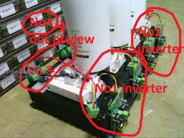 The idea I had since fets will be required was on the side where the igbt's are we could make a pcb that houses multiple 4008's. How many will we need? 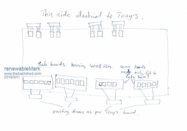 In the design it will need to accommodate the big caps, Tony advised provision for 5 would be wise and perhaps just use three to begin with to see if that's sufficient. Poida, that would all work with the Warp control board, but will that hardware suit your arduino driven design? Can a setup be made that we can use both control boards on? Cheers Caveman Mark Off grid eastern Melb |
||||
| LadyN Guru Joined: 26/01/2019 Location: United StatesPosts: 408 |
I believe the most feature complete version is Andrew's. Poida updated Andrew's code (I am yet to review it for my own understanding) to incorporate grid sync. Before that Andrew's code was functional sans grid sync. It's very likely I am wrong as I am yet to dive into either code in depth. I briefly looked at Poida's code and he immediately got back to me with feedback and more comments that he also updated his own code with. So Poida and Andrew will obviously know which version is more functional, but in my mind, it might make more sense to go with the Andrew/STM32. I will eventually port some bits to the ESP32 but more likely pair up the STM32 dedicated for the control signals and employ the ESP32 for wireless communication and management so I can remotely monitor the inverter without having to look at displays. I got wind that it might be possible to loadshare multiple Warpverters (I don't know how): in that case, this ESP32 might work out to be the master/controller over the individual dedicated STM32 boards. As far as the hardware is concerned, an implicit agreement has been made that the boards will be pin compatible with the Warverter board which has enough real estate to accomodate either a STM32 or a Nano based brain. HTH! (and thanks to each of you for the awesome, brilliant work so far) |
||||
mackoffgrid Guru Joined: 13/03/2017 Location: AustraliaPosts: 460 |
Mark: I have one solution, I think Tinker is doing something else? I have modular Half bridge pcb and Full bridge PCB (100mm x 100mm). These pcb have no electronics on them apart from the FETS to maximize copper. Their driver is another pcb that plugs on top of them. 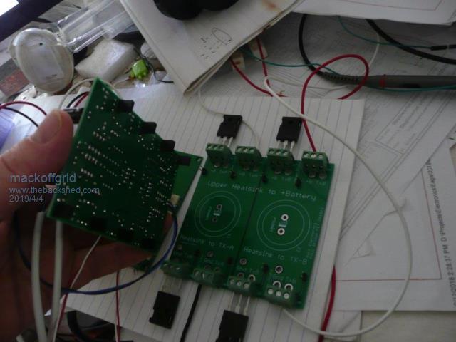 Which goes together like this. (the little drive pcbs are not plugged in on this photo. I have put capacitors underneath. Then with the driver pcbs plugged in. The top heatsink connects positive battery to all the FETS. The bottom heatsinks are sliced up to suit transformer legs. I have used 4mm2 wire (one per FET) to connect to the negative buss. The PCBs are on my Github if anyone is interested. https://github.com/mackelec/StepInverter I'd be interested if there are other ideas out there. Cheers Andrew |
||||
| Warpspeed Guru Joined: 09/08/2007 Location: AustraliaPosts: 4406 |
The alternative control board does not need to be the same physical size, only use the same four plugs and pin connections on the output side, and a similar two pin plug for power on the input side. Unplug a Warp board, plug in Mack board, or a Poida board directly in its place, without having to change anything around. Then anyone can take advantage of future functional upgrades as the whole thing evolves further. Or step back to something more primitive that is known to work. Older obsolete boards can then still remain useful as working spares. Mark, (and others) Probably the easiest way to get started is to just quickly make up eight identical low power half bridge boards that use only two mosfets each. That will limit power to about one to two Kw, but it will give you something that actually works with your four new transformers, and you can then satisfy yourself the the transformers are all working properly, and the transformer winding part of the job is all fully tested and complete. Loading eight small very simple half bridge boards should be pretty straightforward job. The extra surplus small boards can be kept as working spares when the big final board (or boards) are completed. Its then a case of building the big inverter with all the heavy duty capacitors and heatsinks and fans. It all then becomes a step by step process, and having something that actually works fairly early on, and is trouble free, can be a really big confidence builder. Cheers, Tony. |
||||
| Warpspeed Guru Joined: 09/08/2007 Location: AustraliaPosts: 4406 |
Yes it will, less core cross section requires more turns, but we also get a larger hole which provides more room. Klaus's concerns are quite valid, so we need to look into this a bit more. As you have already just fitted four layers of 1.6 wire to your larger core, can you measure or estimate how much that reduced the hole size ? Now that primary wire I suggested has an O.D. of 7.25mm I have some of it right here in fact. In a perfect world we can fit 24 turns onto the first layer, then 18 on the second, 12 on the third, and 6 on the fourth, leaving a 7.25mm hole in the middle for one extra wire. So 24 + 18 + 12 + 6 + 1 = 61 turns. A perfect wire bundle ! And that requires nine wire diameters or 65.25mm. It should all pack through a 70mm hole with a bit of grunting and swearing. Now the sixty four dollar question is, are we going to end up with a 70mm hole after fitting the secondary ? And if not, how much of the inside of the core do we need to remove. Cheers, Tony. |
||||
| Warpspeed Guru Joined: 09/08/2007 Location: AustraliaPosts: 4406 |
Eight of these would be all you need to get started. Fairly primitive, but it is what I am using right now. Eight boards will get you a fully functional working inverter but of limited power output initially. I will e-mail Gerbers to anyone that requests them via e-mail. I cannot attach Gerbers to a Forum post or a PM, so it will have to be by e-mail. 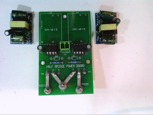 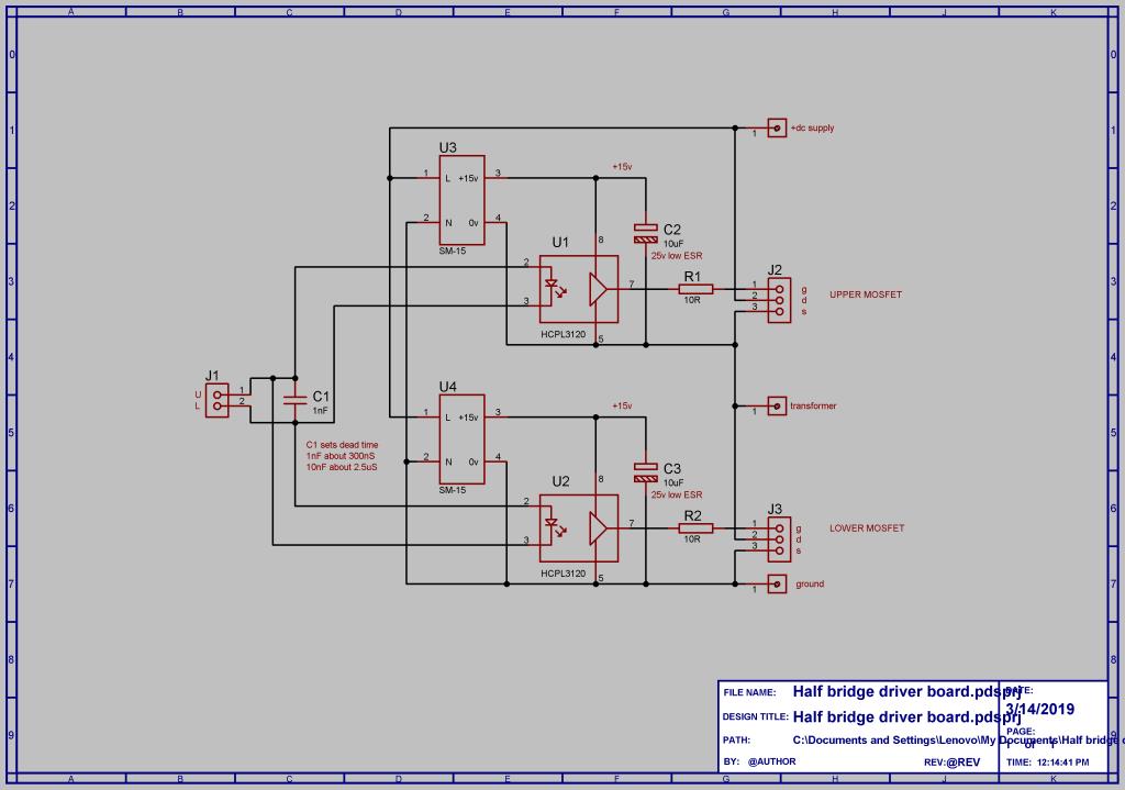 Cheers, Tony. |
||||
renewableMark Guru Joined: 09/12/2017 Location: AustraliaPosts: 1678 |
Just measured my 6kw core, that had 4 layers added to the ID. It started at 100mm and ended up at 80mm. That was with the full 128 turns all fitting on one layer each without having to go over themselves to complete the 128, they all fitted in side by side on the same layer, even the last one. So if the 104 turns all fitted in side by side on one layer, including the 4th winding it should in theory reduce the ID from 87 to 67mm What if I used 2x 2kw cores stacked, I could do less winds then yeah? 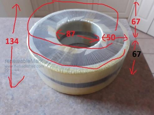 Cheers Caveman Mark Off grid eastern Melb |
||||
| Warpspeed Guru Joined: 09/08/2007 Location: AustraliaPosts: 4406 |
I think I would just go ahead with what you already have, and make an extra special effort to flatten out each secondary layer as much as possible. The very worst thing that can happen is we may have to find some slightly thinner wire for the primary. Just had a thought. I have a drum of that cable here, just weighed it at 1.8Kg, which is only about 11.5 metres of cable, just over one third of a full drum. If you are able to fit 24 full turns over the top of your secondary in one full layer, then 61 turns are going to fit for sure through the remainder of the hole. My guess would be 24 turns requires roughly about 6.5m of cable so there is easily enough there on the drum to try this, but nowhere near enough for 61 turns. How snugly that first 24 turns fit over the secondary should give a pretty good idea of how tight all 61 turns are going to end up. If you are down this way, feel free to pick it up. Cheers, Tony. |
||||
| Mulver Senior Member Joined: 27/02/2017 Location: AustraliaPosts: 160 |
Warp, at what voltage do you suggest to use IGBT's? I am currently harvesting lithium 18650's and contemplating my overall system voltage. |
||||
| Warpspeed Guru Joined: 09/08/2007 Location: AustraliaPosts: 4406 |
There are a lot of very nice large low cost mosfets around that have voltage ratings up to about 100v. They would be a good economical choice at 48v. For 100v and above IGBTs are better in every way. Especially attractive are the big, old, and slow IGBT power blocks rated up to several hundred amps per device. As we are only switching at very low frequency, speed is not a factor. Another aspect altogether are the electrolytics. Energy stored is proportional to voltage squared, and at higher voltages the ripple current reduces as well. So the short answer is, a higher voltage will be a much better and more efficient choice, and have fewer design problems, especially at high to very high power levels. You will probably have noticed there are not too many grid tie inverters running at 48v. Some work at several hundred volts dc, and all of them use fast IGBTs. Its a bit different with a battery though. A high voltage grid tie inverter can all be enclosed inside a sealed box. A large high voltage off grid exposed battery can potentially be a very nasty thing. Cheers, Tony. |
||||
mackoffgrid Guru Joined: 13/03/2017 Location: AustraliaPosts: 460 |
This is my first pass for a schematic for the stm32_WarpInverter. stm32_WarpInverter Im trying not to allow it to get too bloated. We'll see ... Cheers Andrew |
||||
| Warpspeed Guru Joined: 09/08/2007 Location: AustraliaPosts: 4406 |
That looks fine. Cheers, Tony. |
||||
| Mulver Senior Member Joined: 27/02/2017 Location: AustraliaPosts: 160 |
I was thinking of running 30s80p voltage from 90v to 126v but your right they would need to be well enclosed from any possible interference. |
||||
| poida Guru Joined: 02/02/2017 Location: AustraliaPosts: 1419 |
It looks good Andrew. But I probably wont build it. My plans for this project are a bit limited in scope. Already I have 2 functional inverters 3000VA, one is powering the house since Sept '18. I want to build a test warpverter only to explore it's performance and discover benefits etc. And so I don't want to start building more circuit boards. I just recently completed a nanoverter control board. The nanoverter board can drive a warpverter with the addition of a small add-on board, that inserts into the nano1 socket. This will give me all I need (DC LV cutoff, DC OC cutoff, Vfb based closed loop control, inverter run on/off button, power supplies,etc.) This add-on board only needs an Arduino Nano or STM32 BP and a multi pin connector socket. It can and will run from the nanoverter 5V supply. The code running on the nano or stm32 would only run the inverter, with DC V or AC Vfb type control, and have one input : the run/stop digital signal. I'll hack one up on perfboard I think. Maybe even use IRS2004 half bridge drivers, to switch the optocouplers, instead of 74 series logic. The 2004 takes one input and generates complimentary output with deadtime and can drive 130mA, more than enough for the diodes to light up. I intend to run MOSFET based full bridge switches, with isolated DC supply for low and high sides. Many run at non-ground level references, so might as well bite the bullet and get a dozen of the cheap isolated converters Warp used. wronger than a phone book full of wrong phone numbers |
||||
| Warpspeed Guru Joined: 09/08/2007 Location: AustraliaPosts: 4406 |
I run thirty Winston Lithium cells, nominally 100v. No problem with that, I have a two pole battery isolating circuit breaker. Open the breaker and I can work on any cell without even the slightest tingle. If there were young children or pets around I would be a bit more concerned. Cheers, Tony. |
||||
| Warpspeed Guru Joined: 09/08/2007 Location: AustraliaPosts: 4406 |
You will need eight half bridge boards and sixteen (!) of those small isolated supplies. Its not too bad though, all of the electronics including all seventeen small isolated supplies draw a combined total power of five watts with all the opto isolators running. Anything extra above that is just transformer magnetizing current. Cheers, Tony. |
||||
| poida Guru Joined: 02/02/2017 Location: AustraliaPosts: 1419 |
Just tying up loose ends, LadyN suggested I look at the ESP32 as a possible uC for this project. The ESP32 has lots of good things. Wifi, 2 cpu cores, Bluetooth, 2 DAC channels, heaps of flash for program, heaps of RAM, plenty of GPIO, timers,... $15 AU from local source. And you can program it via USB - out of the box, no need to load bootloaders. All good. Today it arrived and the first test I do is to run a tight loop, toggling a I/O pin. This shows if there are any interrupts occurring, that will mess with the timing of inverter bridge gate drive signalling. The below drives pin 2 (the Blue LED) as fast as possible void setup() { REG_WRITE(0x3ff44020, BIT2); } void loop() { REG_WRITE(GPIO_OUT_W1TS_REG, BIT2); REG_WRITE(GPIO_OUT_W1TC_REG, BIT2); } Then we need to examine this activity with the DSO. There should not be gaps in the signal, and there are. These are due to the watchdog function of the chip's OS/bootloader/whatever and can't be turned off. So the ESP32 is not suitable for driving inverters. The Arduino Nano, Uno, Mega and Due ALL can have interrupts disabled such that nothing at all will interrupt your code. This is why I like them. The STM32 is the same in this respect. You can have code run with zero other interrupts mucking up things. But making the cheap Blue Pills work with USB programming is beyond me, I have to use the USB->TTL board, fiddle with switches and jumpers etc. The ESP32 will probably become a supervisor, running a system, but ultimately letting an other uC do the time critical stuff. The wifi is good and easy to use. wronger than a phone book full of wrong phone numbers |
||||
| poida Guru Joined: 02/02/2017 Location: AustraliaPosts: 1419 |
Warp, could you point me to a link where to buy the isolated supplies? wronger than a phone book full of wrong phone numbers |
||||