
|

|
Forum Index : Electronics : Warpspeedís low frequency stepped sine
| Author | Message | ||||
| Tinker Guru Joined: 07/11/2007 Location: AustraliaPosts: 1904 |
Thanks Mike, I will take your advice. Checking more on ebay I found a much bigger selection in the 33000uF/100V range. So I ordered 3 of these: capacitors 25A ripple rating hopefully suffices, these caps are huge so there is plenty of cooling surface. The cheapest 99000uF@100V I could find. Klaus |
||||
| Warpspeed Guru Joined: 09/08/2007 Location: AustraliaPosts: 4406 |
Excellent suggestion there Mike, I just never thought of doing it that way. One other peculiarity about this type of inverter that needs to be known about and understood. The transformer secondaries are all series connected, and the full inverter output current still flows through the transformers that are "off" or in the zero output voltage condition. We cannot just open circuit the primary by turning off all four mosfets. We absolutely must clamp the primary to zero volts by shorting it out, and we can do that very easily by turning on both lower mosfets simultaneously. The drive waveforms to do this are really simple, and its a very important and easily overlooked feature of the control board design. 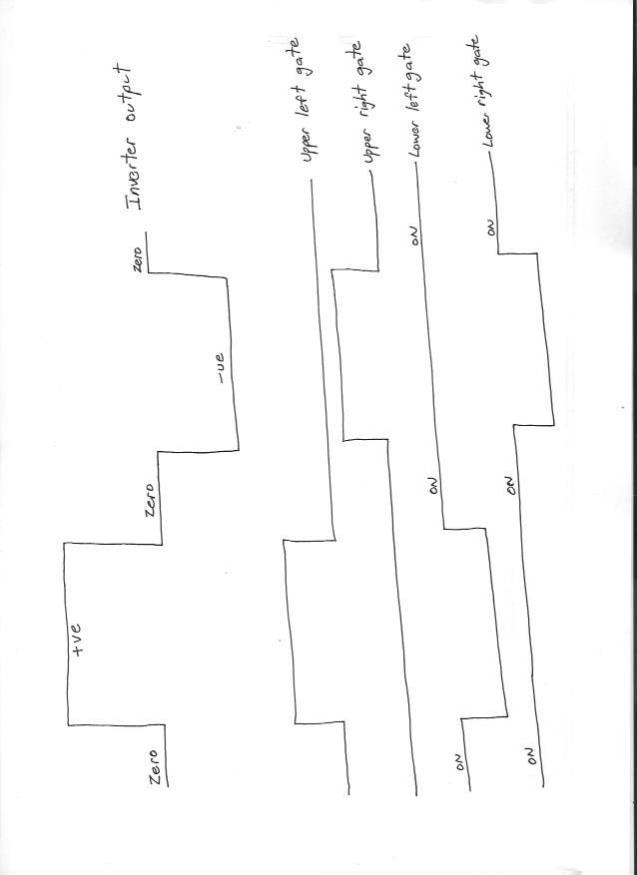 The upper mosfets "U" are driven directly from data coming from the EEPROM. Lower mosfets "L" use the exact same waveform but inverted by HC04 inverters. Dead time is added at the half bridge boards. Klaus, flux density calculation is different for sine and square waves. Sine waves are measured in rms (.7071 x peak) but the flux in the core sees the average value (0.637 x peak) and there is an 11% difference. Faraday's law uses 4.44fnab for sine waves, and 4fnab for square waves. If you use the usual sine wave transformer equations and design all four transformers for 50Hz sine waves it will work fine, and give 11% extra margin on actual flux density. For our hypothetical 40v to 225v square wave transformer, just plug in 40v rms and 225v rms into the transformer design spread sheet, the turns ratio will be correct, and the flux will be o/k too. Cheers, †Tony. |
||||
renewableMark Guru Joined: 09/12/2017 Location: AustraliaPosts: 1678 |
Tony I'm not too bright so it took a little looking at to work it out. So basically you use two IGBT's instead of multiple fets to drive the big 2 inverters. The smaller two are the ones on the back connected to the shiny al strip using mosfets instead of igbt's. 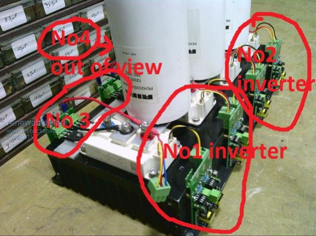 Are these IGBT's ok Re transformers, can you use toroid cores that are too big for the smaller ones, does it matter if they are oversize? It's just the turns that counts isn't it? Cheers Caveman Mark Off grid eastern Melb |
||||
| Warpspeed Guru Joined: 09/08/2007 Location: AustraliaPosts: 4406 |
Yes those IGBTs are pretty much identical to what I am using, and the price is about right for Chinese clones, which is what I have. Only really required for the largest inverter, but I used another pair for the second inverter because I already had them, and it makes a simpler neater physical layout. These are far more suitable for a 100v inverter than a 48v inverter for two reasons. Your current will be twice my current at the same power level. Probably not a problem, but its going to have less maximum overload capacity at 48v than at 100v. IGBTs also drop about two volts each at very high current. That is about 4% conduction loss at 100v but 8% conduction loss at 48v so they are going to develop about twice as much heat and power loss at 48v than at 100v when worked hard. Its certainly workable. It will be slightly less efficient at medium and very high power than mosfets, but infinitely more robust and capable of huge power surges such as motor starts. The two smaller inverters just use individual mosfets, a pair in each half bridge. In my case 600v 50 amp devices, but you would be better off with HY4008's. The transformers only need to be big enough to handle max power. No problem with over sizing the smaller ones. Toroids will be fine, they are just more difficult to wind. I am slowing down in my old age, and let my mate wind my transformers for me. He is no spring chicken either, but he winds transformers for his day job and has all the right gear. For him its just one more job to do with all the other customer orders. Cheers, †Tony. |
||||
renewableMark Guru Joined: 09/12/2017 Location: AustraliaPosts: 1678 |
Thanks Tony, are you happy to share your layout design? If so those wanting a 48v version could use most of your design, but incorporate sub boards to mount the 4008's for the two bigger inverters, same boards for simplicity but maybe fit fewer fets to the second one. Perhaps in the centre another cap board that could house multiple caps, perhaps two rows could fit? 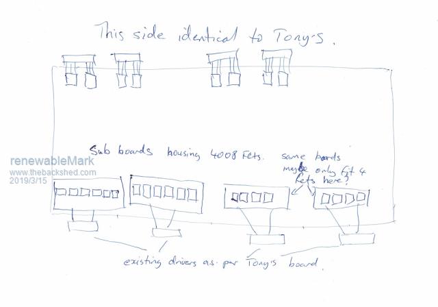 I have a double stacked 6kw core wound for the Oz/Mad unit, so needs a new primary. And have a few 2kw cores that could easily be wound (that doesn't worry me) So looking at it, if you are happy to share your design, this shouldn't actually be too big of a job at all. Cheers Caveman Mark Off grid eastern Melb |
||||
| Warpspeed Guru Joined: 09/08/2007 Location: AustraliaPosts: 4406 |
Sure, the whole idea is to share ideas. Many different ways to lay the thing out. You could even dedicate one large heatsink just for the large inverter, and build the other three inverters onto a second heatsink. Using individual HY4008's will be more electrically efficient at 48v, and a lot cheaper too. I used parts I already had here, so my layout was appropriate. But it would be an expensive thing to do again if I had to go out and buy all the parts. Individual mosfets are going to be a lot more fiddly, and all those mosfets are going to take up a lot more heat sink space than IGBT power blocks. Physical layout will be far less critical switching at 50Hz rather than at 23Khz. Just put plenty of thought into the track widths and the huge currents those tracks need to carry. Andrews solution to all this is particularly clever, and well worth studying. Cheers, †Tony. |
||||
mackoffgrid Guru Joined: 13/03/2017 Location: AustraliaPosts: 460 |
Here is the stm32_Warpverter version. You'll find Eagle files, schematics (pdf) and Gerber files. I'll add the software when its tested with the pin changes. stm32_Warpverter github cheers Andrew |
||||
| JohnS Guru Joined: 18/11/2011 Location: United KingdomPosts: 3802 |
Does that mean that if the output (secondary circuit) is (say) 10A then each of the transformers must have a secondary rated at (min) 10A? John |
||||
| Clockmanfr Guru Joined: 23/10/2015 Location: FrancePosts: 429 |
These 6 pages of Tony's 'WarpStepInverter', will be going in the 2nd edition of the 'How to Make a 6kW OzInverter' book. It will be in the tech chapter 14. 2019-04-07_021019_WarpstepInverter1to5.pdf 2019-04-07_021047_WarpStepInverter6.pdf Everything is possible, just give me time. 3 HughP's 3.7m Wind T's (14 years). 5kW PV on 3 Trackers, (10 yrs). 21kW PV AC coupled SH GTI's. OzInverter created Grid. 1300ah 48v. |
||||
| Warpspeed Guru Joined: 09/08/2007 Location: AustraliaPosts: 4406 |
Yes John. All four secondaries are connected in series, and all four carry the full inverter sine wave output current continuously. Cheers, †Tony. |
||||
| Warpspeed Guru Joined: 09/08/2007 Location: AustraliaPosts: 4406 |
Great stuff Clockman. Thank you for fixing all my typos and spelling errors ! Cheers, †Tony. |
||||
renewableMark Guru Joined: 09/12/2017 Location: AustraliaPosts: 1678 |
I'm trying to work out how to use the existing designs to make a fet driven Warp machine. Mack's construction confuses the hell out of me, but I can get my head around your one Tony. So is it possible to use the std Warp control board and the 8 warp driver boards, but send the signals to the Mack fet board, so each twisted pair would then be separated and sent to each 1/4 like this. 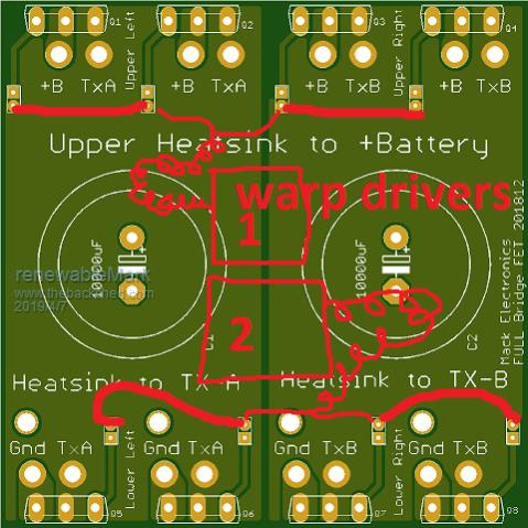 Cheers Caveman Mark Off grid eastern Melb |
||||
| Warpspeed Guru Joined: 09/08/2007 Location: AustraliaPosts: 4406 |
Andrews FET board is a mechanical assembly to tie all the larger parts together physically. It requires a piggy back board with the little 15v supplies, and the opto isolators, in addition to the picture above. The easiest way to get started is with eight of my small half bridge boards with a pair of HY4008's fitted onto each. Bolt all the mosfets onto just a large plain sheet of 3mm aluminium with insulating hadware. The mosfet legs will be strong enough to support the small circuit boards. That will give you a 100% working inverter, but power limited by only having four mosfets in the largest inverter. Andrew is working on a microprocessor board that will plug in directly instead of my control board. Directly swappable, same plugs, same pin connections. Next step would be to get really serious with a proper heatsink, large electrolytics and a whole bunch of HY4008s. But meanwhile, you can have some fun and prove that the whole thing works. The small half bridge boards can be re used for the smaller inverters in the final design. Cheers, †Tony. |
||||
| Mulver Senior Member Joined: 27/02/2017 Location: AustraliaPosts: 160 |
Hi Tony, Have you elaborated anywhere on how your charging your 100v battery pack? Iím curious on how your have tackled this, in conjunction with your direct solar to inverter setup! Cheers Shane |
||||
| Warpspeed Guru Joined: 09/08/2007 Location: AustraliaPosts: 4406 |
Shane, During the day, even on very cloudy days, the inverter draws power direct from the solar panels. The voltage at the inverter input being well above the battery voltage. This allows the battery to have a long slow continuous charge for about seven hours at mid winter, and seventeen hours at mid summer. My battery is quite small, only 50Ah, so the bulk charging current is set fairly low at 10 amps. It charges at 10amps constant current (if available) up to 3.4 volts per cell, then the charging current tapers down above 3.4v to zero at 3.45v. Charging is controlled by a battery monitoring system which monitors and displays the voltage of each cell on a 17 inch flat screen video monitor. Its the highest voltage cell that always takes control of charging. As soon as the highest voltage cell reaches 3.45v charging terminates for the day. The cell voltage display has a peak hold, so I can see the highest and lowest voltages each cell has ever reached. At night the solar panel voltage falls to zero, and this resets the charger so the charging process can begin again the next day. My cells receive one long continuous charge that then terminates, and then one long discharge at night. From what I have read, that is the best way to get longest battery life, as few as possible charge and discharge cycles. I also have individual cell balancing resistive loads at each cell, only 27 ohms (about 130mA). The loads are at each cell, but the on/off control for these balancing resistors is controlled by central software that uses the same voltmeter for monitoring every cell. That makes it very easy to keep all the cell to cell voltages within a very few mV at the end of charging, where the cells normally can tend to go a bit wild. The whole thing has been a long slow process of steady development and improvement, and at this stage I am very happy how the whole battery management system is performing. This is a quite an old picture, and the cell voltages are a bit all over the place compared to where they are now. 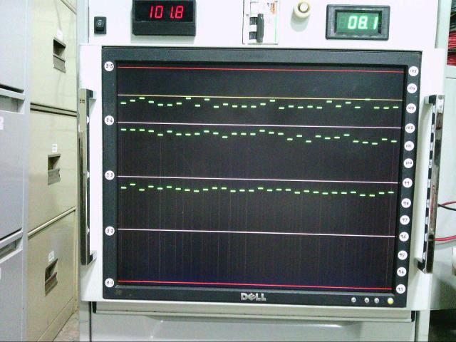 Cheers, †Tony. |
||||
| Mulver Senior Member Joined: 27/02/2017 Location: AustraliaPosts: 160 |
Thanks Tony! Did you develop your own charge controller? Iím assuming your charging the whole pack direct from the panel voltage? How are you controlling the current? PWM? Cheers Shane |
||||
| Warpspeed Guru Joined: 09/08/2007 Location: AustraliaPosts: 4406 |
Yes its all home brew. Its just an ordinary garden variety buck converter that runs in constant current mode. The battery charger started out being completely self contained, and having its own analog control system that referenced overall battery voltage to control the charging current. Constant charging current up to 102 volts (30 x 3.4v). That then tapered down to zero at 103.5v (30 x 2.45v). That is currently being modified so it will very soon be software controlled by whichever cell happens to be at the highest voltage. The BMS has a d/a converter that sends a control voltage to the charger, and that directly controls the charging current. Overall battery voltage is not a good indication of what the highest and lowest cell voltages are doing, particularly during the final stages of charging. The cell voltages go a bit frantic and start to rise at an ever faster rate above 3.4 volts, which is why the current needs to be tapered right down. The voltage rises so very fast at 3.45v there is really no point in going any higher. It might get to 3.5v in less than a minute, and that extra 60 seconds of charging just cannot store any extra energy. So I terminate charging at 3.45v which many people might argue is extremely low. I think you first need to get a Lithium battery, monitor it and watch what it does, then plan a charging and cell balancing strategy based on your own observations and experience. For me this has been a continuous learning experience over the last couple of years, but I think I am now getting pretty close to having it work how I think it should best work. Cheers, †Tony. |
||||
| Mulver Senior Member Joined: 27/02/2017 Location: AustraliaPosts: 160 |
Thanks! As we have just moved I have the opportunity to really think about how I should setup my system. Iím currently up to 700 capacity tested 18650ís goal is 2400. With 12 transformers and some more programming would it be possible to configure a 3 phase version of the step inverter ? |
||||
| Warpspeed Guru Joined: 09/08/2007 Location: AustraliaPosts: 4406 |
Yes definitely three phase would be possible, either with my hardware control board, or Andrew's software control board. The way I would do it would be to have three standard Warpverters each running from its own control board, each with its own crystal oscillator and voltage correction. The voltage on each phase would be corrected during the zero crossing for complete waveform continuity in the usual way. The frequency divider that divides the crystal frequency down to 50Hz could be reset with a very narrow pulse to phase lock the zero crossing point. The synchronising pulses to do that would originate from a master synchronising board with its own crystal to ensure an exact 120 degree relationship. Andrew has come up with the exact same scheme, using a similar master 120 degree phase reference source, for phase locking his three microcontrollers. Cheers, †Tony. |
||||
| Mulver Senior Member Joined: 27/02/2017 Location: AustraliaPosts: 160 |
Thanks Tony! So this would be in a star configuration on both primary and secondary? Would there be benefits in running delta primary to star secondary? As the eg8030 (3 phase version) wiring diagram suggests? Please accept my limited understanding of 3 phase transformers  |
||||