
|

|
Forum Index : Electronics : Poidas "Inverter Software Control" Topic.
| Author | Message | ||||
| wiseguy Guru Joined: 21/06/2018 Location: AustraliaPosts: 1156 |
Ok - I am hearing that you are well aware of these little "anomalies" and you have wrung every last ounce of performance from the hardware and software. I did not know if I had discovered an error or a problem or apparently something of monumental inconsequence. I am more than happy to continue on as is & yes we do have some reasonable control of performance and behaviour going forward, unlike the 8010 which you had to take or leave as is. Sorry if I distracted you a lot with my queries. Now go do some paid work to make your boss happy ! If at first you dont succeed, I suggest you avoid sky diving.... Cheers Mike |
||||
| wiseguy Guru Joined: 21/06/2018 Location: AustraliaPosts: 1156 |
In the interests of keeping software questions & replies in the one place I have copied a post and an answer that probably belongs here. If at first you dont succeed, I suggest you avoid sky diving.... Cheers Mike |
||||
| wiseguy Guru Joined: 21/06/2018 Location: AustraliaPosts: 1156 |
it has been a while since I've looked at your project. I assume you are using the code "nano_1_v7_no_bessel_mike.ino" Yes, you probably need to add pinMode(6,INPUT) If you still can not drive D6 HIGH then there is a problem. When not using the SCR shutdown input, you can use if (((PINB & 0x01) == 0) ) instead of if (((PINB & 0x01) == 0) || ((PIND & 0x40) == 0x40)) When using the former, we only are using D8 as the run/stop command. If it's high, the inverter runs. Using the latter will stop the inverter when D6 goes high OR D8 goes low. The code (PINB & 0x01) is the same as but much faster than digitalRead(8) (PIND & 0x40) is the same as digitalRead(6) (edit) I just checked a few things. I made no pinMode() statements in a program and after booting, the Arduino Nano has about 0.1mA output on a pin. 0.1V. I suppose that is tristate? After I placed the pin to INPUT, the same current and voltage. INPUT_PULLUP applies an internal pull up resistor to the pin's output and I saw 15mA and 5V With pinMode(x,OUTPUT) I saw 80mA which seems a bit high but no worries If at first you dont succeed, I suggest you avoid sky diving.... Cheers Mike |
||||
| wiseguy Guru Joined: 21/06/2018 Location: AustraliaPosts: 1156 |
Thanks Poida - I added the line "pinMode(6,INPUT);" and voila it worked !! I now have a working latched shutdown for over current. When the latch is reset the nano does a soft start and resumes where it left off (assuming D8 (run) is still high. Now on with the testing..... If at first you dont succeed, I suggest you avoid sky diving.... Cheers Mike |
||||
| poida Guru Joined: 02/02/2017 Location: AustraliaPosts: 1419 |
good news. I hope you find this as fun to play with as I do. wronger than a phone book full of wrong phone numbers |
||||
| wiseguy Guru Joined: 21/06/2018 Location: AustraliaPosts: 1156 |
Poida thanks for creating the Variac code - it made testing the hardware independent of a feedback loop a real cinch. If you ever revisit the code a couple of nice to haves are: 1) after D4 (pin11) is set low a soft stop before pin8 is clobbered 2) after D4 (pin11) is set high, enable pin 8 and then a soft start up to the pot setting would be nice - it is a bit brutal as it is to turn the switch on/off with a high pot setting. 3) The ability to regulate to the pot setting would be great, but the ability to disable this feature so it still operates exactly like it does now is very important. I think I'll eventually need to lean on you to try to get the regulation issue sorted out, however I will see what I can achieve with hardware first. From the distortion picture on the "nano,roll your own" post do you have any off the cuff suggestions ? If you have encountered this before - maybe there is a cure already ? If I tried to put into words from what I see in the waveform, its somewhat assymetrical its like the first 90 degrees and the next 90 degrees are quite different in the array. Are you able to suggest what might be going on to get this distortion? Is the integral set too high ? would having a rolling average of the previous 4 or 8 reads (cycles) help? Edited 2019-11-07 23:51 by wiseguy If at first you dont succeed, I suggest you avoid sky diving.... Cheers Mike |
||||
| poida Guru Joined: 02/02/2017 Location: AustraliaPosts: 1419 |
Mike, first the distorted output: It could be due to Vfb signal quality. PWM duty % is adjusted at about zero crossing of the 50Hz output, so it occurs just before each of the 1/2 wave outputs. One output looks OK and one does not. The adjustment is a single change to the amplitude of the pwm scale factor that is applied to the 200 pwm cycles. The code you are running (v7_no_bessel_mike) has no low pass filtering on Vfb. It expects a clean signal and this signal to have a DC component mainly, with much smaller AC parts, eventually getting to near zero signal at 20-50Hz. The nanoverter design includes an active low pass filter on Vfb. I have not characterised it yet. (hang on..) Here is 15V at 50Hz, the AC Vfb in, what results after full bridge recification and smoothing (i.e. input into the active filter), and finally the filter's output. Dark Blue is Vfb in, Light Blue is after the diode bridge/filter input and Pink is filtered output which is what nano1 ADC channel sees. 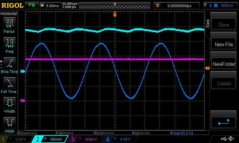 when fed 10Hz, a lot more comes into the filter input and some passes out. 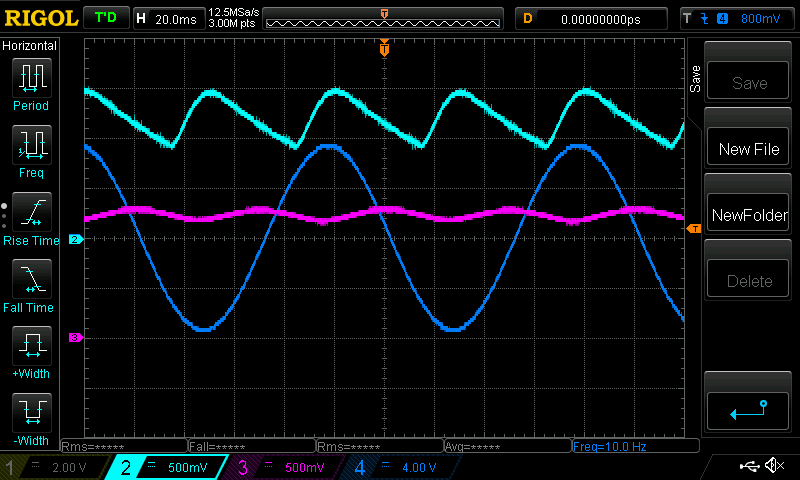 This is why the nano1 code works well without the digital LF filter. It gets a clean signal. What does your Vfb signal look like, after all conditioning, measured at the same signal potential as the ADC input pin? I found it a little tricky to get the above 2 DSO captures. The function generator references signal ground to 240AC supply EARTH. And the DSO references it's input grounds to 240AC supply EARTH. This means for 1/2 of the input AC (+15 to -15V) fed into the diode bridge, it will get shunted to signal ground. I avoided problems by using an isolation transformer for the 240V supply of the fun-gen. This way I could bring both Vfb input wires below ground while having CRO probe grounds connected to the nano's signal ground. wronger than a phone book full of wrong phone numbers |
||||
| poida Guru Joined: 02/02/2017 Location: AustraliaPosts: 1419 |
"Is the integral set too high ? would having a rolling average of the previous 4 or 8 reads (cycles) help?" I'm not sure of the signal conditioning you apply to Vfb. Let's look at a known setup where Vfb is sent into a diode bridge, smoothed via a 10uF or so cap and then straight into the ADC port. This is much like what I used when developing the nanoverter code (prior to the great work of tinyt) I used a digital LF filter and saw it could improve stability of the control loop to near perfection. If I used filter values such that too much time delay was present, then the control loop grew unstable. Too much delay is like a LF filter with Fc set to about 2Hz. From memory I think I settled on an Fc of 10Hz, Bessel 2 pole LF filter. An average of the previous 4 or 8 samples might help. But probably not. The average of samples is a low pass filter too, but a poor one. Sample rates are important too. The code you are using samples Vfb at about 4KHz. This is happening continuously and then a flag is set to run the control loop code which occurs once every 10ms. The latest value of Vfb converted from the ADC is used. If you average the previous 8 samples, you will get a value that won't have as much noise of frequencies like 2KHz or 4Khz. This 8 value sample will still let through gross changes in signal of 50Hz or there about. My inverter code works with the assumption that when the control loop runs, the value of Vfb is a noise free and true value. When using zero filtering, I sometimes got something like what you have got. The control loop was doing it's best to produce output given a rapidly changing input from Vfb. I must repeat that over the course of a 50Hz output waveform, adjustment to the output amplitude is made twice only, just before the start of each 1/2 wave. This adjustment is used to scale (to make the output AC more or less) the subsequent 1/2 wave. Looking at I think the closed loop control is arriving at the point where it needs a large scale factor for the 1/2 wave that is positive. The 1/2 wave that is negative appears good enough for now. I wonder if Vfb signal at the ADC input is not very smooth. The shape of the positive 1/2 is very reminiscent of what I saw when I ran a test inverter with 40Hz output, sending the toroid well into saturation. Dark Blue is AC voltage, Light Blue is primary winding current. 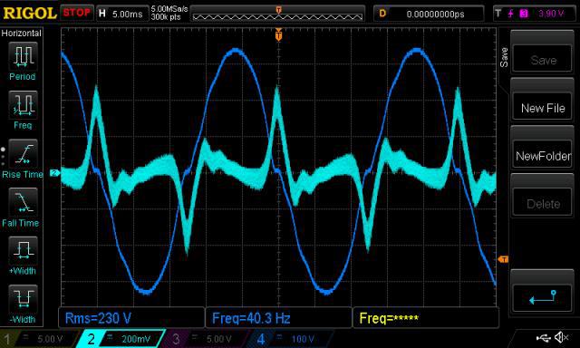 My guess is the positive 1/2 wave is using an amplitude control value of near maximum. And after then it becomes a more reasonable value for the negative 1/2 wave. When developing the inverter code, I had my MOSFETs saved many times thanks to a current limited bench supply & small bulk caps. I could get away with murder time and time again. Clearly to me you need to keep using current limit devices until we get to the bottom of this. Could you stick a probe on Vfb as it is sent to the ADC input, DC coupled? We might learn a bit about what's going on. Also, obtain the output of D7, the signal I use all the time to synchronise the DSO. This short pulse is output just before one of the control loops is executed. You can use horizontal delay to check out what is on Vfb right when the control loop is run for both 1/2 waves. Edited 2019-11-10 17:05 by poida wronger than a phone book full of wrong phone numbers |
||||
| Warpspeed Guru Joined: 09/08/2007 Location: AustraliaPosts: 4406 |
Poida, one rather sneaky technique I remember (not my idea) to generate dc proportional to amplitude of a sine wave, is to multiply the sine wave with a cosine wave of identical amplitude in an analog multiplier. The cosine wave could be generated by an all pass filter of some kind, to produce two outputs with 90 degree phase difference and identical amplitudes. That should be fairly easy as our 50Hz frequency is constant. Any residual ripple produced by harmonic distortion should be of a much higher frequency and lower amplitude, and should be easy to get rid of. No rectifier required to do this either. As you will already know, Sin x Cos = 1 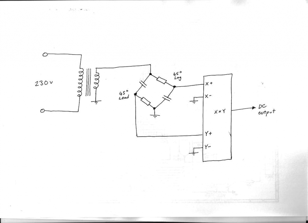 The big advantage of this method is speed of response to amplitude changes without the heavy low frequency pulsing that rectification produces, or any long time constants. That is the sticks and glue analog way to do it. It may be possible to do something a bit more clever in software, I really do not know. How about a rotating stack with ninety degree length. Then multiply the current instantaneous measured sine wave value, by the ninety degree old historical stored value in the stack. This will need to be proper four quadrant multiplication, and the output should be a steady constant positive value proportional to amplitude (plus any inherent noise). Edited 2019-11-10 17:54 by Warpspeed Cheers, Tony. |
||||
| poida Guru Joined: 02/02/2017 Location: AustraliaPosts: 1419 |
sin(x) + cos(x) <> 1 for all x, maybe only when x = 0 or pi,2pi etc. sin(x) * sin(x) + cos(x) * cos(x) = 1, for all x on the other hand. So I need 2 more multipliers if I want to go analog. But I could use stored samples, and do the sum of squares thing. I will experiment maybe. Edited 2019-11-10 21:37 by poida wronger than a phone book full of wrong phone numbers |
||||
| Warpspeed Guru Joined: 09/08/2007 Location: AustraliaPosts: 4406 |
Its well worth a try. I know that its already been successfully done in analog, and used in a commercial product, but have never seen an actual schematic. I have only read about the concept a very long time ago and the exact details are all rather foggy. But the possibility is there. Cheers, Tony. |
||||
| Warpspeed Guru Joined: 09/08/2007 Location: AustraliaPosts: 4406 |
sin(x) * sin(x) + cos(x) * cos(x) = 1, for all x on the other hand. Yes you are quite right. sin(x) * sin(x) will produce a sine wave of double the frequency with a dc component. If you do that again with the same waveform delayed by ninety degrees (cosine) that too will generate a double frequency waveform with a dc component. The ac components of each will be in exact antiphase, and will cancel when the two waveforms are finally added together leaving just the dc. The sum of squares using a delayed value and a current instantaneous value should achieve the exact same result in software. Cheers, Tony. |
||||
| Warpspeed Guru Joined: 09/08/2007 Location: AustraliaPosts: 4406 |
I am so very intrigued by this idea, I simply had to have a go. So I connected up an all pass filter consisting of two 47nF and two 68K resistors in a bridge (Xc = R at 50Hz). That produced two 50Hz sine waves with ninety degree phase difference and equal amplitudes. My capacitors were both closer to 48nF than 47nF so I lowered my frequency a bit to compensate. 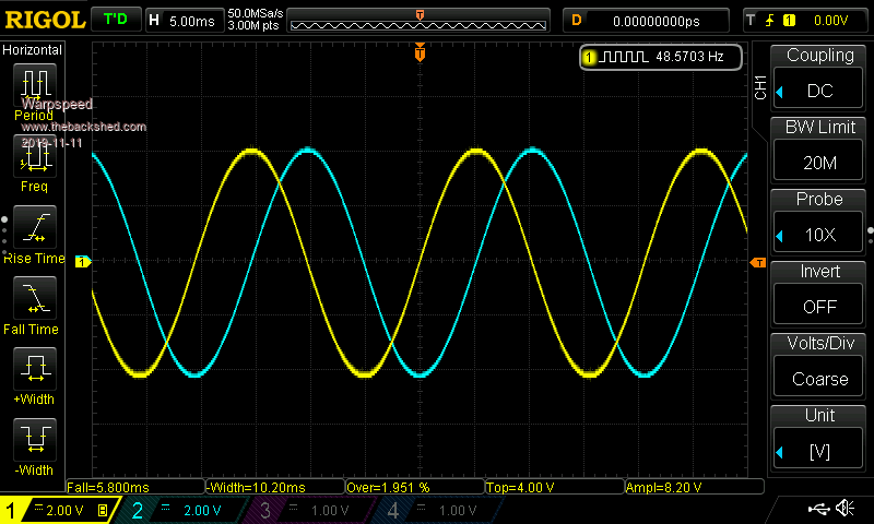 I then breadboarded up an AD633 analog multiplier connected as a squarer, and did indeed get a twice frequency sine wave output that has a dc component. It clearly sits above ground with a positive dc offset as expected. 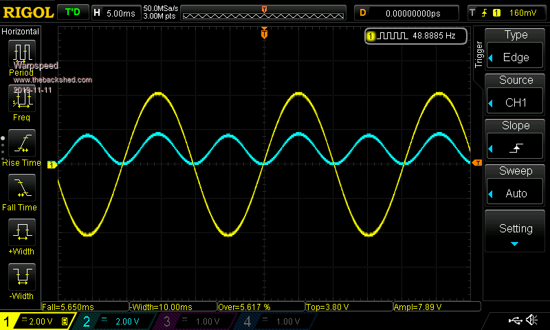 Added a second squarer to the cosine waveform, and combined the two antiphase waveforms together with a couple of resistors. The purple trace shows a slightly wobbly dc voltage. The purple trace is one volt per division not two, so its about +1v volt dc. I could have varied the scale factors of the multipliers to get more than that, but did not bother. This is just a rough test. 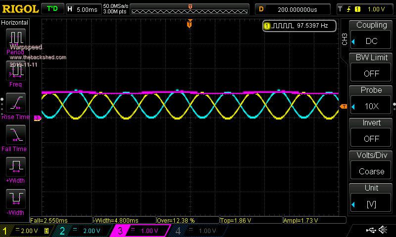 So it does in fact work, and should work much better with real numbers in software rather than having problems with 50Hz hum, dc offsets, and component tolerances. This should convert ac into dc as a steady continuous process, without the violent pulsing produced by rectification. And it can be done without adding any significant delays or long time constants to filter out the resulting ripple of rectification. 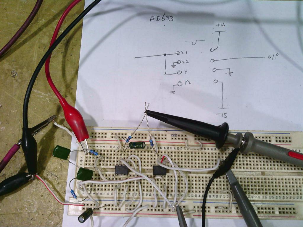 Edited 2019-11-11 10:59 by Warpspeed Cheers, Tony. |
||||
mackoffgrid Guru Joined: 13/03/2017 Location: AustraliaPosts: 460 |
Very nice. The AD633 aren't real cheap though. What is the reaction time to a varying AC? |
||||
| Warpspeed Guru Joined: 09/08/2007 Location: AustraliaPosts: 4406 |
So I connected up an all pass filter consisting of two 47nF and two 68K resistors in a bridge (Xc = R at 50Hz). That produced two 50Hz sine waves with ninety degree phase difference and equal amplitudes. My capacitors were both closer to 48nF than 47nF so I lowered my frequency a bit to compensate.  I then breadboarded up an AD633 analog multiplier connected as a squarer, and did indeed get a twice frequency sine wave output that has a dc component. It clearly sits above ground with a positive dc offset as expected.  Added a second squarer to the cosine waveform, and combined the two antiphase waveforms together with a couple of resistors. The purple trace shows a slightly wobbly dc voltage. The purple trace is one volt per division not two, so its about +1v volt dc. I could have varied the scale factors of the multipliers to get more than that, but did not bother. This is just a rough test.  So it does in fact work, and should work much better with real numbers in software rather than having problems with 50Hz hum, dc offsets, and component tolerances. This should convert ac into proportional dc as a steady continuous process, without the violent pulsing created by rectification. And it can be done without adding any significant delays or long time constants to filter out the resulting ripple of rectification. That is important for stability and response when optimally tuning a PID feedback system.  Cheers, Tony. |
||||
| Warpspeed Guru Joined: 09/08/2007 Location: AustraliaPosts: 4406 |
The AD633 aren't real cheap though. What is the reaction time to a varying AC? Just had a look on e-bay, five for twenty dollars is not too bad. https://www.ebay.com.au/itm/5pcs-AD633JN-AD633-Low-Cost-Analog-Multiplier-DIP-8/251919464577?hash=item3aa791f881:g:cO0AAOSwBLlVLTuO I don't imaging anyone would ever build an analog version of this into an inverter, it could be done far better and much more easily in software using the same basic principle. Feed the ac voltage direct into the a/d converter through a transformer, and just crunch the numbers. A sudden step amplitude change (in either direction) should be fully recovered in ninety degrees or 5mS. It requires that for the "historic" delayed cosine data saved in ram to correct to the new changed amplitude setting. That should really tighten up the achievable stable response of the PID control loop. Edited 2019-11-11 11:49 by Warpspeed Cheers, Tony. |
||||
| poida Guru Joined: 02/02/2017 Location: AustraliaPosts: 1419 |
This is interesting alright. I played a bit with an Excel spreadsheet last night. It could let me add a little phase offset to the cos() since I wanted to see what would happen if the ADC sample timing was a little off. I still remain in the digital world it seems. I knew the analog implementation would work perfectly and it must have been satisfying to do it. (by the way, I see you have the Rigol DS1054Z or something like it. How do you like it so far? My view is that it's great value but never a $2K Keysight competitor. Very worthwhile investment.) My concerns are related to the fact that the AC voltage output from an inverter when powering real world loads is not a pure 50Hz sine. There are other frequencies there. How does the sin^2 + cos^2 approach work with not insignificant harmonic components? The active low pass filter of the nanoverter crushes all (to insignificant levels above 50Hz. Maybe put a few harmonics in there with the 50Hz. 20% of the 3rd, 15% of the 5th. See how it goes? I know the digital approach will fail when there are harmonics present. My mantra is: Low pass filter then process. That is, remove all more than 50Hz but the 50Hz and then process. wronger than a phone book full of wrong phone numbers |
||||
| wiseguy Guru Joined: 21/06/2018 Location: AustraliaPosts: 1156 |
Tony - I like the multiplier rectifier - a unique approach - but Im fresh out of multipliers in my goodies box right now, need to order a few more. Poida,Thanks for your replies and comments, I had forgotten that you had created some code for me to try just before I had to put the project aside for a while - and it remained untried until today when i found it again. The code was 2019-05-28_100414_v5-wg.zip. The inverter behaved much better with some relatively small distortion on the 50Hz waveform. Now that I could run the inverter safely I was able to scope Vfb, and what a fine mess it was ! Here is where I lose some (all?) credibility, but it has to be called as it is.....do I really have to post the waveform...........ok here it is warts and all. This is not how it behaved during bench testing, not sure if I have phasing wrong or what. The sample and hold is supposed to hold the peak value until about 3+mS after the zero crossing whilst you read it (2ms after zero cross?), before enabling it again for another few milliseconds until after the next peak. Instead what we see is about 1.5mS after the zero cross the sample and hold becomes live again. I will look into this probably Wed - busy until then. Another few pics, the next one is one of the bridge drive output just before the choke, rise-time is quite snappy. Now the fall waveform. And finally the waveform driving 1KW. I think as soon as I sort out Vfb it will be a goer. Poida I am a little confused at the Vfb. I thought I read that it is updated at I think it was a 4.5khz rate, then somewhere else I thought it just sampled once or twice depending on the code for each complete sinewave. Then I read that we want to remove everything except the 50Hz component & process, somewhere I dont think I understand the correction process after Vfb is sampled. I found the original part and quote "An important point on the digital filtering: Since we are sampling Vfb at approx 4500Hz" - why do we sample so fast? I was expecting to read a DC voltage proportional to the output peak or rms and it would be re read and updated once each cycle and applied to a complete waveform. I hope you can help clear up my confusion for me. If at first you dont succeed, I suggest you avoid sky diving.... Cheers Mike |
||||
| Warpspeed Guru Joined: 09/08/2007 Location: AustraliaPosts: 4406 |
(by the way, I see you have the Rigol DS1054Z or something like it. How do you like it so far? Yup, its a DS1054Z, and all the extra features were already unlocked except for bandwidth. I plan to figure out a way to measure transient and frequency response on an unmolested 50Mhz unit, before I apply the demon tweak. Then measure it again. Very happy so far, it was largely your praise that persuaded me to take the plunge. Glad I did. Still learning how to drive it, lots of things to select and to play with.... My concerns are related to the fact that the AC voltage output from an inverter when powering real world loads is not a pure 50Hz sine. There are other frequencies there. How does the sin^2 + cos^2 approach work with not insignificant harmonic components? The harmonics will be "stationary" and should add some up and down humps and bumps to the dc, but should not effect the overall average dc value. That should have little or no effect on the integral part of a PID, but the proportional part might introduce some unwanted harmonic distortion. Don't really know for sure, but it might still be worth trying. The active low pass filter of the nanoverter crushes all (to insignificant levels above 50Hz. That would be the way to do it, have a fairly steep low pass filter to clean up the measured inverter waveform. It cannot be any worse than the raw 100Hz ripple output of a rectifier !! My mantra is: Low pass filter then process. That is, remove all more than 50Hz but the 50Hz and then process. Yes absolutely, agree 100% Cheers, Tony. |
||||
| poida Guru Joined: 02/02/2017 Location: AustraliaPosts: 1419 |
.. Poida I am a little confused at the Vfb. I thought I read that it is updated at I think it was a 4.5khz rate, then somewhere else I thought it just sampled once or twice depending on the code for each complete sinewave. Then I read that we want to remove everything except the 50Hz component & process, somewhere I dont think I understand the correction process after Vfb is sampled. I found the original part and quote "An important point on the digital filtering: Since we are sampling Vfb at approx 4500Hz" - why do we sample so fast? I was expecting to read a DC voltage proportional to the output peak or rms and it would be re read and updated once each cycle and applied to a complete waveform. I hope you can help clear up my confusion for me. the function "loop()" is executed as fast it can be. It works out to be about 4kHz. There are two versions of nano1 code. One low pass filters Vfb, and one does not. But both sample Vfb at 4KHz and store the most recent value. Now, when it comes time that the AC output crosses zero, a flag is set to enable the closed loop control PD code to execute. This will use the last ADC conversion of Vfb. Depending on which versions, Vfb will be low pass filtered or not. The current or latest nano1 code has no LP filtering and so it requires a LP filtered input (which is obtained from the active LP filter design on the nanoverter board) Some may think it's wasting time to needlessly convert Vfb each time loop() is executed. This not a problem, nano1 code has plenty of time to do this. Now that the current code has no digital LP filter, the continuous Vfb conversions are not needed. But when I was digitally LP filtering Vfb, I had to have a good long history of Vfb samples ran through the IIR low pass filter to ensure that when the time came to execute the closed loop PD control code, a good and filtered Vfb value was available. wronger than a phone book full of wrong phone numbers |
||||