|

|
Forum Index : Electronics : nanoverter build
| Author | Message | ||||
| tinyt Guru Joined: 12/11/2017 Location: United StatesPosts: 438 |
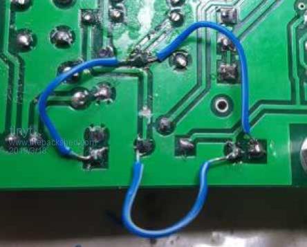
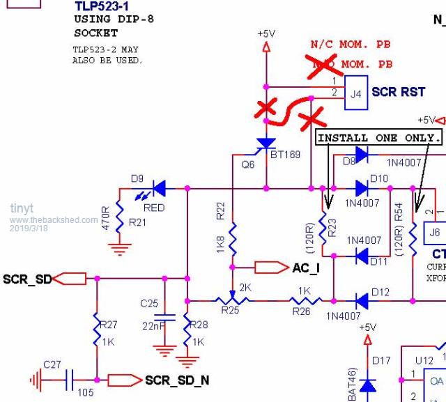
It is very hard for me to see if the trace at the J4 pin was cut. Please confirm.  If the simulated AC current is zero, I think there should be no voltage at the scr gate and cathode. Here is the schematic section with the intended mod in red.  I am still checking my mod instructions for errors. |
||||
| poida Guru Joined: 02/02/2017 Location: AustraliaPosts: 1418 |
Tinyt, my bad. I did not do that other trace cut. It works perfectly. I really must pay attention to my instructions more often. If the switch is left open, the inverter can be restarted manually but the SCR protection is not enabled. We need to source a decent quality NC PB. The drawing above shows what we need, thanks for that. I could not get my head around it when looking at the original schematic. It still is 0.16V at the gate with zero input to J6. This is not a problem since the SCR triggers at about 0.83V wronger than a phone book full of wrong phone numbers |
||||
| poida Guru Joined: 02/02/2017 Location: AustraliaPosts: 1418 |
I think the 0.16V might be coming from SCR_SD_N which is a 5V source from nano1 pin D6 This flows through R27 (1K) then R28 (1K) to ground. at R27-R28 node it will be 2.5V, maybe, then this goes to the R25 trim pot then the wiper takes some through R22 to the SCR gate. The current drawn by the J6 input from the 0 - 5V signal test is only about 0.5mA This is a tiny load for any current transformer to deal with. wronger than a phone book full of wrong phone numbers |
||||
| tinyt Guru Joined: 12/11/2017 Location: United StatesPosts: 438 |
Thanks poida, I did not look at the overall schematic were that voltage is coming from. |
||||
renewableMark Guru Joined: 09/12/2017 Location: AustraliaPosts: 1678 |
Poida, have you intentionally left out either 120R r23/54? Thanks for the new software. Tinyt thanks for the mod instructions/ pics. Cheers Caveman Mark Off grid eastern Melb |
||||
| poida Guru Joined: 02/02/2017 Location: AustraliaPosts: 1418 |
Mark, I have not fitted either R23 or R54 to the board. I am using some random current transformer pulled out of the failed 3000VA Victron, with varying resistors across it's output pins. This permits me to discover things about a current transformer, the noisy environment it's in and other things. When I come to use the nanoverter board with a home inverter, I will not use the SCR OC function, only the DC OC function, as well as a large DC contact breaker. I built the SCR OC circuit so as to test it against the code that runs in both nanos. wronger than a phone book full of wrong phone numbers |
||||
renewableMark Guru Joined: 09/12/2017 Location: AustraliaPosts: 1678 |
This one should be fine yeah? Cheers Caveman Mark Off grid eastern Melb |
||||
| Tinker Guru Joined: 07/11/2007 Location: AustraliaPosts: 1904 |
Its what I use, it works for me  Klaus |
||||
renewableMark Guru Joined: 09/12/2017 Location: AustraliaPosts: 1678 |
Got all the mods done, was about to fire up a new power board when the coopers stubbies got the better of me. I'll fire it up tomorrow. Cheers Caveman Mark Off grid eastern Melb |
||||
| poida Guru Joined: 02/02/2017 Location: AustraliaPosts: 1418 |
Mark, I need to watch out for the Green ones. They're the worst. I have found Sierra Nevada Torpedo Extra IPA is a fine brew and am nearly in need or another one right now. The code will trip correctly, and as expected, when enough voltage reaches the SCR gate, from the voltage divided signal from the "current transformer" terminal. Hopefully you will find a good position for the trimpot. I am just fiddling around the margins now, trying to get support for a meaningful display of AC current on the LCD. So much noise... The last versions of the code still stand as what you need to use. wronger than a phone book full of wrong phone numbers |
||||
| tinyt Guru Joined: 12/11/2017 Location: United StatesPosts: 438 |
In one of my projects, when the potentiometer is exactly in between two values, my code kept flooding the host with the flip-flopping values. Tried the moving average in the atmel apnote, still did not work. Somebody suggested to add hysteresis in the code, was able to do it but lost precision (instead of 256 values, it became 128 only). Struggled for weeks to restore precision, works but has flaws when changing direction, also when nearing or coming from the min and max stops. |
||||
renewableMark Guru Joined: 09/12/2017 Location: AustraliaPosts: 1678 |
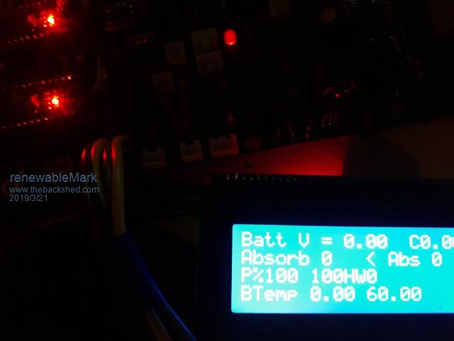
OK got the machine running with full fets and caps, no bang, ran blowheater and shed air con, perfect wave. Can't get LCD to work. previously did Tried the lcd in another device and it works fine. I included lc 57...library. Cheers Caveman Mark Off grid eastern Melb |
||||
| poida Guru Joined: 02/02/2017 Location: AustraliaPosts: 1418 |
good news. When you visited last, I thought we saw your LCD + I2C interface board did not work. We proved this by swapping my LCD + I2C unit and seeing it work fine on my board and your two boards. Did you get another LCD unit? And see it work properly? Just checking details from the dark remnants of my memory. wronger than a phone book full of wrong phone numbers |
||||
renewableMark Guru Joined: 09/12/2017 Location: AustraliaPosts: 1678 |
Yes that lcd went in the bin. Machine runs properly so the code is in the nano's ok LCD lights up, it works in the mad control board so it does function. I beep tested sclsda lines and they look fine. Updated usb drivers so got me stuffed. Cheers Caveman Mark Off grid eastern Melb |
||||
| johnmc Senior Member Joined: 21/01/2011 Location: AustraliaPosts: 282 |
Good Mark , Grins all   round with nanoverter. round with nanoverter.cheers john johnmc |
||||
renewableMark Guru Joined: 09/12/2017 Location: AustraliaPosts: 1678 |
Yeah the machine works fine so far, haven't given it any real curry, only 2kw load so far. The shed ac didn't stuff the wave up like to 8010 did, so that is very promising. I don't want to let it loose on the house till I get the lcd working though as it needs the parameters monitored. Edit, I give up, re installed arduino software started from scratch, same result. Initialise arduino lcd lights up, arduino flashes a few times and lcd goes blank. Cheers Caveman Mark Off grid eastern Melb |
||||
renewableMark Guru Joined: 09/12/2017 Location: AustraliaPosts: 1678 |
Tried the mad gti nano in the nanoverter board, that works, gives out a screen, so the wiring is fine, something in how the sketch is being put on there, got me stuffed. Poida, I might need to to burn an arduino for me.  Cheers Caveman Mark Off grid eastern Melb |
||||
| poida Guru Joined: 02/02/2017 Location: AustraliaPosts: 1418 |
Mark, I have no idea what is the cause of this. Maybe I visit you this weekend, and bring my boards and LCD. I have changed my board so that both nanos are in sockets. This means we can just put my known good nano2 in your board, with my known good LCD. wronger than a phone book full of wrong phone numbers |
||||
| tinyt Guru Joined: 12/11/2017 Location: United StatesPosts: 438 |
For the LCD that I purchased, I cannot get the backlight on unless I do a hardware mod or add the 'setBacklight' as follows: lcd.begin(20,4); // LCD stuff lcd.setBacklight(255); // <<< lcd.clear(); |
||||
renewableMark Guru Joined: 09/12/2017 Location: AustraliaPosts: 1678 |
Thanks Tinyt I tried that but didn't work. I can load the mad gti software onto the nano 2 and the screen displays correctly with three different screens, there must be some difference in the sketch that allows the Mad one to work. 2019-03-22_134322_Madness_regulator.zip Thanks for the offer Poida, you're always welcome over. Cheers Caveman Mark Off grid eastern Melb |
||||