
|

|
Forum Index : Electronics : Random Unexplained Inverter Failures
| Author | Message | ||||
| zaphod Regular Member Joined: 03/06/2018 Location: United KingdomPosts: 93 |
Hi Wiseguy a very good find! I have been using PIC processors for years in various power conversion projects and have often found bugs however when submitting the to the PIC forum I just get attacked by the resident trolls so have given up trying to enlighten others by that means. Submitting technical queries direct to Microchip has little effect either (it's like being put on perpetual hold). I have tried other alternatives like STM32 but always there are undocumented bugs to catch the unwary. As far as I can make out all the vendors compete with feature lists however they fail to test the features leaving that to the customers. So a warning for anybody considering replacing your asic with a micro don't believe the data sheets!! I have got so fedup with the situation that I am seriously considering the fpga route for pwm's being the only way I can ensure I am not at the mercy of someone else's poor implementation and testing. Of course the downside of that is integration level that being a major advantage of mpu's however given the amount of time I spend debugging, designing work-arounds and sometimes even having to change the mpu with a consiquent severe re-design I am changeing my opinions regarding integration. Sorry if this sounds like an offtopic rant but I wanted to draw your attention to other potential implementations and there pitfalls. I should also mention the software for sine wave generation is extremely simple being a table lookup job and there are plenty of websites to get the tables from. It would also be simple in vhdl/verilog for an fpga implementation. Cheers Roger 1Kwp DIY PV + Woodburner + Rainwater scavanger :) |
||||
| wiseguy Guru Joined: 21/06/2018 Location: AustraliaPosts: 1156 |
Hi Zaphod I can sure relate to your comments. I too have had the royal runaround from some top manufacturers. The following come to mind easily Dallas with their temperature chip DS1820 and woeful temperature drift. Our equipment was controlling a winery tank farm. Some tanks held 235,000 litres and the issues caused excess heat and they were going to sue at $2.30 a litre. Luckily when the ferment finished it actually tasted great so we dodged a bullet. Thank god the DS18S20 fixed the issue - I didnt like my chances of suing Dallas. Dallas with a DS1232 watchdog chip which would latch up - my watchdog needed a watchdog.... Atmel with their AT17LV65/128/256 3 different prices same innards. At the time they only made the 256 part and hoped that users dont discover the extra memory in the cheaper parts (not sure if this is still done). We programmed a smaller 65K part filling the whole 65K with data and then got it to recirculate from terminal count of course it had a huge dead area, once we programmed the same code 4 times over presto it worked. Took a couple of weeks of crap before they owned up. Microchip with their 16F676 part after initial release - their faulty part blew up my first 500W inverter with bad output port timing. Cirrus logic with their power monitoring IC that was suppose to be pin compatible but with extra features & a few poorer ones thrown in. On one occasion after much grief I threatened to tear up the floor of the lab and we would grow potatoes or something simple but more rewarding.... The trouble is each win actually makes you feel like you lost, you never get compensated and they jerk you around till you prove the issue & then they fess up that they knew all along ! I am not planning to put a micro-controller to run my inverter - I will build a Warp 4 transformer switching unit before I do that. The closest I would go to that is a supervisory micro that oversaw starting stopping and household chores. End of rant. If at first you dont succeed, I suggest you avoid sky diving.... Cheers Mike |
||||
| Warpspeed Guru Joined: 09/08/2007 Location: AustraliaPosts: 4406 |
Have to agree Zaphod that is the conclusion I have reached myself, and where I am at the moment. A purely hardware digital approach with just a big PROM containing multiple lookup tables, and a few counters and latches is all that is really needed for a fully functional nuts and bolts PWM sine wave generator with continuously variable output amplitude. But you will find zero interest in such a simple basic work horse on this Forum. Cheers, Tony. |
||||
| gaspo Regular Member Joined: 25/06/2018 Location: AustraliaPosts: 65 |
Wiseguy, added TL431 and a combo through hole/SMD crystal. I do not think there is more room for anything else. Attached are all necessary engineering files for manufacturing. 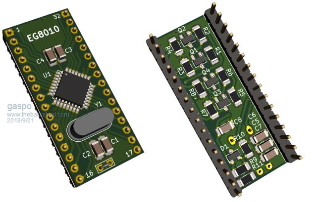 2018-09-21_223224_EG8010-adapter-files.zip |
||||
| wiseguy Guru Joined: 21/06/2018 Location: AustraliaPosts: 1156 |
Aw crap I just finished my huge new list of add-ons. - Just kidding Gaspo - I don't want for anything else. I like that you managed to fit 1206 instead of 0805 - a bit easier to handle & solder. If you can, an extra via or two on the larger ground plane is always better. I recently bought a thin diamond blade table saw for accurate PCB cutting. how many adaptor boards could you fit onto the one file of a 100 x 100mm Prototype pcb with at least a 1.5mm gap between boards & with a overlay line either side to help the aim ? Thanks for your input Im enthused enough to order a batch of boards and cut them up. Then we need a volunteer.....hey Mark where are you when we need you - I know your inverter is indestructable  If at first you dont succeed, I suggest you avoid sky diving.... Cheers Mike |
||||
| gaspo Regular Member Joined: 25/06/2018 Location: AustraliaPosts: 65 |
There is no need for cutting. PCB makers like JLCPCB let you panelise smaller boards onto the 100x100mm PCB with V-cuts between them. You just snap-off the boards from each other and file the edges a bit. JLCPCB charge about $A30 for 10 100x100mm PCBs with 2-5 days DHL shipping. You can fit 10 adapter boards onto one PCB - so about $3 per 10. I could order and post it if more people interested or you can pick it up if in Perth. Gerbers with more GND vias. 2018-09-22_003535_eg8010-adapter-gerber.zip |
||||
| Clockmanfr Guru Joined: 23/10/2015 Location: FrancePosts: 429 |
Hi Gaspo, Looks a nice adapter board for keeping any shoot through under control. Yes please, I would like to purchase a few boards from you to test. I am in France. I am doing 3 OzInverters at present, and never had any problems with my boards, but as 'Warpspeed' has mentioned there are many variable's at play. But I can see that this adapter board Modification may be an extra sweet solution to any possible problems in the future. Thanks to you and 'wiseguy' for a sensible discussion. Everything is possible, just give me time. 3 HughP's 3.7m Wind T's (14 years). 5kW PV on 3 Trackers, (10 yrs). 21kW PV AC coupled SH GTI's. OzInverter created Grid. 1300ah 48v. |
||||
| tinyt Guru Joined: 12/11/2017 Location: United StatesPosts: 438 |
Nice work Gaspo. One comment if I may. Looking at the footprint for the crystal, it seems that the top copper pads are rectangular and a bit too large. They are also exposed. 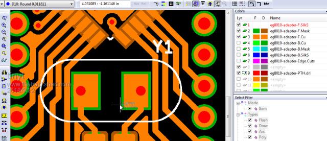 If the crystal is packaged in metal, the bottom metal case of most of them extend too close to the pins. If the crystal is soldered with its bottom flush to the pcb surface, the case can short the pads together. Maybe make the top pads into small anular rings (as small as possible) or make the top solder mask cover the top pads up to the drill holes. No need to change the bottom pads. Just my suggestion. |
||||
| Warpspeed Guru Joined: 09/08/2007 Location: AustraliaPosts: 4406 |
Excellent work there Gaspro. The safest solution to the crystal problem is to fit an proper insulating spacer between the crystal and the board. These are readily available at very low cost. Best way might be to buy a bag of these spacers and provide one with each circuit board. These are particularly good as they are nice thick ultra tough nylon, not just something stamped from an ultra thin plastic sheet: https://www.ebay.com.au/itm/100pc-TQ-06-Crystal-Oscillator-Insulator-Washer-11-2x5-0x1-0mm-PG-HC-49S-HC-49-/130871999210 ?hash=item1e78943aea Cheers, Tony. |
||||
renewableMark Guru Joined: 09/12/2017 Location: AustraliaPosts: 1678 |
Mine is certainly not indestructible, but yes it has survived numerous over current shutdowns just fine, it's all cased up running the house, I have a spare running set of boards, that have already offered to Poida to play with, I'm half way through finishing my second Madinverter, but that won't be finished for a while. Poida is more than welcome to use my spare set ( just the boards, no spare torroid so far) I really think someone should test if the shoot through is actually making it to the fets and it's not just in the chip. Cheers Caveman Mark Off grid eastern Melb |
||||
| wiseguy Guru Joined: 21/06/2018 Location: AustraliaPosts: 1156 |
Thanks Warp I fired up the PC to duplicate your post - you beat me to it. I have not conveyed everything going on in my head yet. For those wanting to take advantage of the better quality Vref supply, the TL431 part needs a minimum of 1mA to regulate to spec so Pin 17 of the adaptor board will need to be connected to the 12V line, the 5V line supply on pin 17 is a no go if using the TL431. A series resistor of 5K1 gives a current around 1.3mA - I would suggest though to use a 3K3 and have a spare 1mA for the input current of Vref which does not seem to be defined on the EG8010. Thanks Gaspo job well done - I was unsure if you were just offering the layout to the group - if you are happy to continue on that is great. I do want to get back to my own design. I must be a tight wad I was going to get the boards from PCBWay I believe they are $5 for 10 off 10x10cm boards but last time I asked for a quote on V-grooving it was like $60 more. Thanks for the information about JLC. As it appears to be getting closer to manufacture I will take a more serious quick look tonight - I have commitments all day today. If at first you dont succeed, I suggest you avoid sky diving.... Cheers Mike |
||||
| gaspo Regular Member Joined: 25/06/2018 Location: AustraliaPosts: 65 |
The reason for the square top pads on the crystal is that both the SMD and the HC49 packages can be used. I have these SMD crystals that I want to use. You can solder HC49 crystal so there's some gap between the board and the metal can or use some kind of spacer as Warpspeed suggested. Wiseguy, I have no problem ordering the boards as I also would like to get the improved adapter board. I will keep couple of PCBs and send remaining 8 to others. I could order more if there is greater interest. JLCPCB offer free panelisation if done by them. I like their ordering page where upon uploading the zipped gerbers it will show you the board in the online gerber viewer. Clockmanfr, I can send to France but you'll need to bear the cost Australia Post. The 3 PCBs are about 100g. |
||||
| tinyt Guru Joined: 12/11/2017 Location: United StatesPosts: 438 |
Now I understand. Another option is if using the SMD, solder it at the bottom or if using the HC49, solder it at the top. If the top pad is unchanged, use spacer per Warp or temporary shim when soldering. Or if the top pad is changed per my suggestion, no need for extra part. |
||||
| poida Guru Joined: 02/02/2017 Location: AustraliaPosts: 1418 |
This is just a follow up for Tinyt: I had a look at the problem with all 4 dead time settings. Here are the 4 DSO captures of the same event, being resume after over temp. in order they are: 500ns 300ns 1us 1.5us 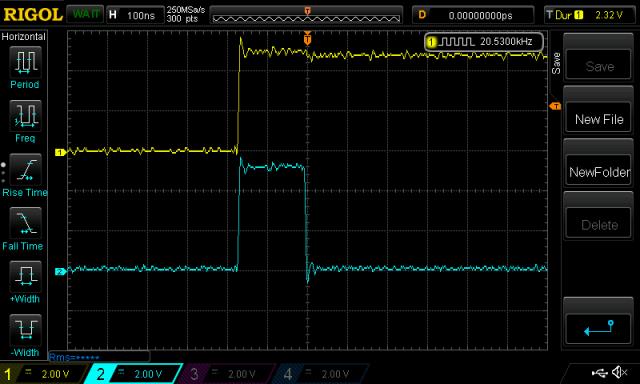 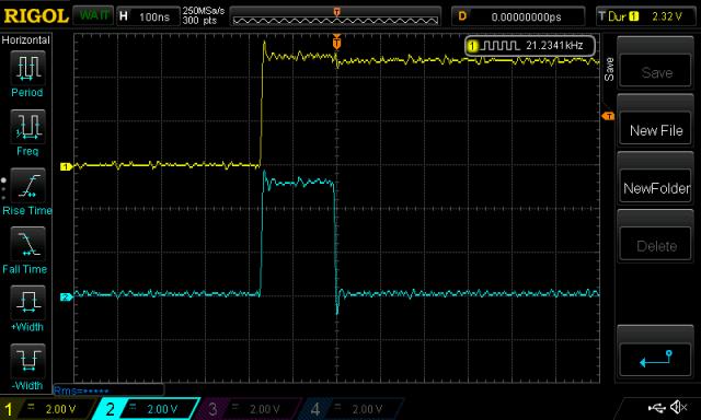 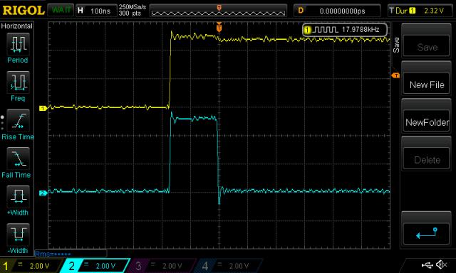 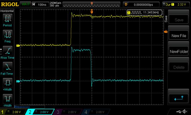 I see no difference in any of these. I confirm the dead time setting of the last one with this: 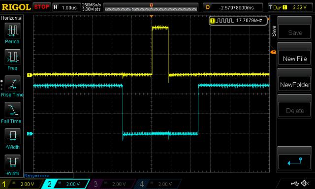 See the 1.5us dead time either side of the yellow pulse high. wronger than a phone book full of wrong phone numbers |
||||
| Clockmanfr Guru Joined: 23/10/2015 Location: FrancePosts: 429 |
Thanks gaspo that would be great. I will PM you with my postal address, and let me know the P+P and costs I will reimburse you, Paypal ok ? Thanks again. Everything is possible, just give me time. 3 HughP's 3.7m Wind T's (14 years). 5kW PV on 3 Trackers, (10 yrs). 21kW PV AC coupled SH GTI's. OzInverter created Grid. 1300ah 48v. |
||||
renewableMark Guru Joined: 09/12/2017 Location: AustraliaPosts: 1678 |
Poida, would it be an idea to test it at the fet itself to see if that is getting to the fet with the different dead time settings? Cheers Caveman Mark Off grid eastern Melb |
||||
| Clockmanfr Guru Joined: 23/10/2015 Location: FrancePosts: 429 |
Gaspo, As mentioned, here is....... This is my latest OzControl board, rev15, and its PDF for components required, although this might not be exact. I have shipped about 60 Ozcontrol boards around the World, and as I said, once the OzInverter is switched on, in general, it stays on 24 7. There is also team of guys doing OzInverters in Africa they were doing 3000. But as this project evolves I get the impression that folk want to play and switch the inverter on and off like a domestic appliance, and maybe that's not so good, but no one has said anything to me. Once built correctly, and followed Oz's wonderful construction instructions in the OzInverter Book, ISBN 9780993590306, and followed its rules, then the OzInverter just works. History........ I needed a decent inverter end of 2015, Fell out big time with SMA, (gagging order on me). At the time 2015-16, 'Oztules' pushed forward and experimented with the 8010. I did the double ounce copper Power board, but its heavily built with lots of power spread and board design elevating pinch points. As I do Micro engineering, my boards were designed for longevity and harsh environments, think insects, high humidity, vast temp ranges. So we have wider than normal tracks and large areas around via's to allow repairs without substrate separation. With conformal coating I like to think that the boards are good for 20 years or so and are easily repaired. OzInverter project mantra........ KEEP IT SIMPLE, MAKE IT ROBUST, and very importantly. KEEP IT COST EFFECTIVE. This particular OzControlRev15 board is not manufactured yet. Thanks again 'gaspo'. 2018-09-22_184703_OzCntrl15.zip 2018-09-22_184947_PCBOzContrlBrd12bdList.pdf Oh yea..... We are not a commercial organization..... but here at 'Le Vivray' we have a philosophy of helping with sustainability and renewable energy concepts. We therefore produced a OzInverter book and the PCB's as a non commercial project. We are not a charity, we just want our expenses back. The Future.... Here in France one or two folk are waking up and helping and I might display the OzInverter at the Paris tech show next year, (minimum cost on a small bench in a corner). Yes, already had brickbats from the French electronic guys, but my boys and friends are French, then the brickbats turn into praise, real funny watching the light come on in their faces. Manufacturing OzInverters.... No way just to many hurdles to jump through. But may get my boys to do a kit of parts, as another option with the Second edition of the OzInverter Book. Everything is possible, just give me time. 3 HughP's 3.7m Wind T's (14 years). 5kW PV on 3 Trackers, (10 yrs). 21kW PV AC coupled SH GTI's. OzInverter created Grid. 1300ah 48v. |
||||
| wiseguy Guru Joined: 21/06/2018 Location: AustraliaPosts: 1156 |
Hi Clockman, nice to hear from you, thanks for your post and very relevant comments. I must find a copy of your latest book - it will help fill in some more detail. What program do you recommend to open your cam files - I usually use Altium but it wont import them. I tried to send you a PM on a few occasions over the week but the response is: "Clockmanfr has exceeded the maximum number of Private Messages they are allowed to receive" Sometime if you can resolve that I can message you. If at first you dont succeed, I suggest you avoid sky diving.... Cheers Mike |
||||
| wiseguy Guru Joined: 21/06/2018 Location: AustraliaPosts: 1156 |
Gaspo, I missed your comment to me in your earlier post. I would like to get a board sometime in order to play with the TL431 and study its effects. If you would/can include whatever other parts you have on hand - even an smd crystal, I would be happy to compensate you - I have EG8010's & can assemble it ok myself. I mostly have 0805's and smaller stuff. Congratulations - it appears you just became an exporter overnight  If at first you dont succeed, I suggest you avoid sky diving.... Cheers Mike |
||||
| gaspo Regular Member Joined: 25/06/2018 Location: AustraliaPosts: 65 |
Wiseguy, I have most of the smd parts except of TL431. I could send some 1206 parts with the boards. I have both 12MHz crystals smd and through hole. I'm currently away until next Friday, Chinese have few days holidays next week so no point ordering boards until then. Take your time inspecting the design making sure there are no issues. Let me know the values of resistors around the 431 part. |
||||