
|

|
Forum Index : Electronics : recycling those Aerosharp chokes
| Author | Message | ||||
renewableMark Guru Joined: 09/12/2017 Location: AustraliaPosts: 1678 |
The way I see it is the steel core does a good job. Warp tested mine and it performed very well, it's saturation was well past 100A. From my own hands on experience, some loads upset it just a tad. With the double ferrite in series that gets resolved. So it appears the two have different properties and using both was certainly a good idea in my case. So perhaps it's not just about saturation, there seems to be something else going on that the ferrite does better than the steel. Tinker you may find if you looked at the sine with every single different load in your house, you'll probably find one that will distort the wave just a bit. Here is a pic of mine while it was all being tested prior to going in a case. The steel one on the left is made from two 3kw aerosharps glued together. You can't see from the angle but the one on the right has two sets of the E70 cores under that clamp. 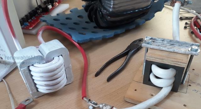 Cheers Caveman Mark Off grid eastern Melb |
||||
| Tinker Guru Joined: 07/11/2007 Location: AustraliaPosts: 1904 |
Nice picture, very informative. You are game gluing the cores together, I prefer being able to take it apart since I'm always modifying things  . .I will try that dual ferrite core idea, a good excuse to take the ferrite E-core chokes sitting here, doing nothing, apart and turning two into one. This is something I did not think about. Perhaps the ferrite choke is better with high frequency distortions. My rarely used microwave certainly does funny things to the otherwise neat sine wave. I did try turns around a large ferrite ring, about 100mm diameter, but that did not work well at all. Klaus |
||||
renewableMark Guru Joined: 09/12/2017 Location: AustraliaPosts: 1678 |
I still have terrible waves from the microwave and my inverter air con on low settings. That's why I'm building a Warp cascade unit. Microwaves are probably the most horrible thing you can plug into an off grid inverter, I cringe every time my wife uses it now. Cheers Caveman Mark Off grid eastern Melb |
||||
| BenandAmber Guru Joined: 16/02/2019 Location: United StatesPosts: 961 |
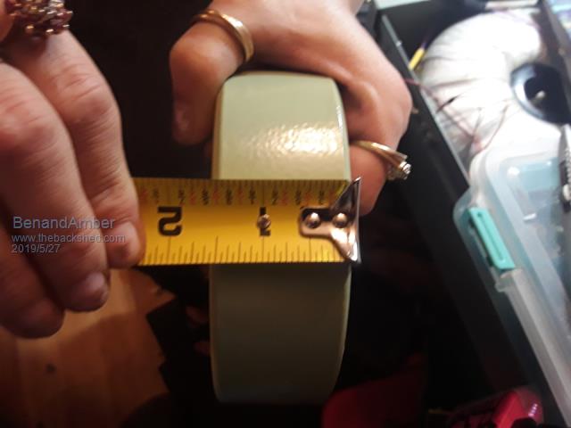 I have this very large ferrite toroid choke in my 10000 watt China inverter board About 130mm by 40mm the choke was originally designed for a inverter It had a lot more turns On It originally then it does now It took 18 or 19 turns to get the uh two around 50 that was very surprising to me I figured it would only take a few turns I am really hoping for good results I was able to use 16 in hand instead of just 10 on the smaller choke I made From some of the stuff I've read the bigger the better other stuff I've read people said they haven't worked out just like was stated above in this post I have two other chokes ready to go if this one don't work out Question is if it don't work out does it blow everything or is it just as simple as changing out to a different one Without a scope it's going to be hard for me to determine which choke is the best Have any of you guys seen that computer scope it's pretty cheap And I could get broken old laptop for pretty much free to fix and use with it Software would be the biggest problem I don't want to get another- cease and-desist letter from Bill Gates I have this inverter pretty much done I could fire it up at any time I've just chickened out I'm kind of waiting around until I get the power jack going 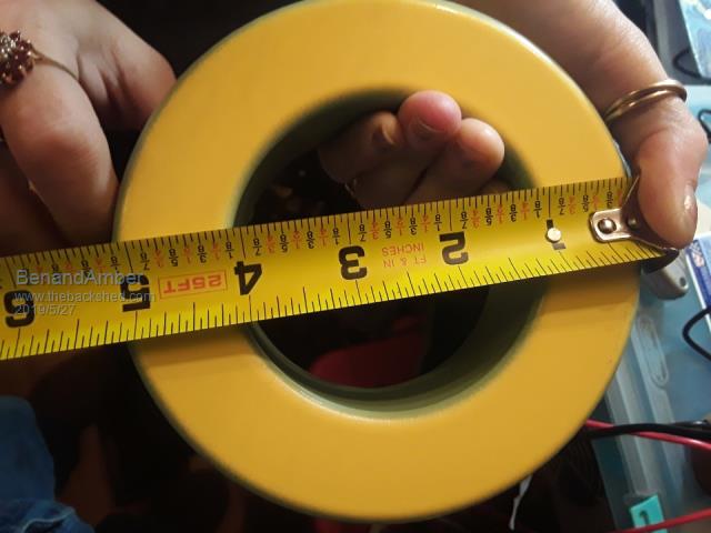 be warned i am good parrot but Dumber than a box of rocks |
||||
| nickskethisniks Guru Joined: 17/10/2017 Location: BelgiumPosts: 458 |
I used a single etd59 core with 13turns, airgap tweeked for 50uH. Only 10mm^2 wire but it gets active cooling. That's the last part of the inverter that's still not finished. It's already saturating @40A, but verry good idle results. I didnt tune the thing, 2uF is what looked the best looking @ waveforms. I did try the tuning thing but the results we're not verry clear with my setup. I did a lot of testing/experimenting but iron inductors or combinations were not succesfull with me, so I gave up. I stil have Nice feritte cores waiting to be wired. My OZinverter is full-time in action from september, it did almost 800kWh without any problems of blow ups, fingers crossed. It's time that I do an update of my inverterbuild... |
||||
mackoffgrid Guru Joined: 13/03/2017 Location: AustraliaPosts: 460 |
I've just finished dismantling the larger AeroSharp Choke core - Thanks to Tinker for the instructions. The electric hot air - paint stripper gun worked well. I've been thinking about a general use core for chokes but with a bigger window area - so I can use insulated wire instead of magnet wire. So I contacted these guys. AEM Cores I've not had much to do with them but they seem friendly. They'll do any size core but like a minimum window height of 30mm. The new customer price is about $11 / kg. I neglected to ask if there was any setup fees. I don't think they have minimums but I think 10 offs would be right for the above price. For reference those large AeroSharp cores are about 500 grams ea. 35mm wide x 13mm buildup (thickness) Window area 17mm x 56mm I'd reckon a 2kg core would make a decent core for 100 + amps, and over 100uH. I haven't done the math or thought about dimensions yet. Cheers Andrew |
||||
| Tinker Guru Joined: 07/11/2007 Location: AustraliaPosts: 1904 |
Andrew, these are the small AeroSharp cores. There are two of them in the 3KW Aerosharp. But there is also a single, bigger, core with a 70 x 20mm window. Sometimes this one is inside an aluminium box, potted in grey gunk. That gunk is soft and easily dug out with a screw driver. I used two of these epoxied together to make an E core. A combined 45mmsq of wire and 18 turns is the max I can fit in that window, giving about 100uh and I set the gap to saturate close to 200A It works a treat. Using other than enameled wire would require quite a large window to fit the size & turns I mention above. It would be easier to wind though, no lathe required  . .Klaus |
||||
| gaspo Regular Member Joined: 25/06/2018 Location: AustraliaPosts: 65 |
Here's what Klaus means to wind the choke properly with a lathe - 18 turns/45mmsq. He wound this one for me, thanks Klaus  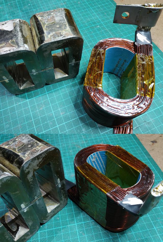 |
||||
mackoffgrid Guru Joined: 13/03/2017 Location: AustraliaPosts: 460 |
Klaus, Oh, I do have a metal can potted with grey gunk  So then I have 3 sizes of aerosharp iron cores. Out of interest, what is the material you wind your wire onto ? Wood with a plastic or cardboard cover layer? So then I have 3 sizes of aerosharp iron cores. Out of interest, what is the material you wind your wire onto ? Wood with a plastic or cardboard cover layer?That choke sure is beautiful, well beyond my skill level, 18 turns of 45mm2 - amazing. Excellent result too, 100uH at near 200Amp sat, truly superb. Cheers Andrew |
||||
| Warpspeed Guru Joined: 09/08/2007 Location: AustraliaPosts: 4406 |
That is the secret. The more copper you can squeeze onto any core, the more you will be able to get from that core in every respect. The rule of thumb way to optimise a choke design goes something like this: 1/ Work out the wire gauge required that will be able to carry your maximum expected current without excessive temperature rise. 2/ Determine how many turns of that wire will fill all of the available space in the window. 3/ Using some much thinner junk wire, wind on a large number of temporary experimental turns onto the core, and with some arbitrary air gap find the saturation point and measure the inductance. Now suppose our hypothetical choke core can fit 15 turns of the final wire size that we have decided will do the job. And we start our inductor testing with 75 turns of junk test wire and a 2mm air gap. Now these following figures are not real, just some imaginary figures I am making up. Suppose our test inductor with 75 turns and 2mm gap saturates a 42 amps. We can conclude from that the core falls over at 75 x 42 ampere turns = 3,150 ampere turns. If we replace the 75 turn test winding with our proposed final 15 turn winding, it's still going to saturate at 3,150 ampere turns. So we can expect saturation to occur at 3,150 divided by 15 = 210 amps. Now that might be o/k as is, or if we want an even higher saturation current, we can open up the gap and test again with 75 turns and maybe a 3mm gap. A larger gap will give a higher ampere turns at saturation figure, but it will reduce the inductance. We may decide we don't need 210 amps and closing up the gap a bit will more usefully increase the inductance. So we get to trade off saturation current and inductance by tweaking the air gap. More turns with a larger gap will give us a potential increase in both, but we have already decided 15 turns is all that is going to fit onto the core. What about inductance ? You can measure that by the rate of current rise at the known applied dc voltage of the inductor tester. Inductance in uH = applied dc voltage (volts) x time of rise to peak in microseconds, divided by peak current reached (amps) So if you apply 22 volts dc, and the current rises to 43 amps in 1,200uS, the inductance will be: 22v x 1,200uS divided by 43 amps = 613.95 uH (for 75 turns and 2mm air gap) Now inductance is proportional to turns squared. To work out the inductance of only one turn, we divide by 75 twice. 613.95 divided by 75 = 8.186 uH divided by 75 again = 0.10914 uH for one turn. For 15 turns we multiply 0.10914 uH by 15 twice. 0.10914 x 15 = 1.6372 uH multiplied by 15 again = 24.5 uH So we have worked out that 15 turns and a 2mm air gap on that particular core has only 24.5 uH of inductance and saturates at 210 amps. We can try again with a smaller air gap and see how that goes. Or we might try stacking two cores together and do some more testing. Its a trial and error process to find something that has both sufficient inductance and a sufficiently high saturation threshold. Cheers, Tony. |
||||
mackoffgrid Guru Joined: 13/03/2017 Location: AustraliaPosts: 460 |
Thanks Tony. I need to build one of Mike's Saturation tester and do this job properly. Having said that, I did find some of those bigger chokes. The wire they wound onto this thing is approx 3mm dia, so 7mm2. I figure if I re-configure this, what I presume is a common mode choke into a single choke with 2 parallel windings. Diagonally connecting the windings in parallel gives me 1mH on my component tester - yes, I know the reality will be different. So if use two of these chokes in parallel I'll have 28mm2 choke at somewhere like 500uH and guessing a 60 amp saturation based on their spec being 15Amp. 200 Amp is more like what I want but this should give me something more to play with. Cheers Andrew |
||||
| Warpspeed Guru Joined: 09/08/2007 Location: AustraliaPosts: 4406 |
If this really is a common mode choke, it will have four wires coming out from it, and very likely have no airgap at all. On the other hand, it may be the usual PWM primary series choke with just two wires and an air gap, which would make it much more suitable. Cheers, Tony. |
||||
| Tinker Guru Joined: 07/11/2007 Location: AustraliaPosts: 1904 |
Andrew, that saturation tester is a must if you want to build chokes like mine. However, a lathe is required to do wind these. You will find it much harder to wind a tight winding with 3mm wire, I used 1.8mm wire wound two strands simultaneously (5mmsq). I did try to re configure the existing windings of these chokes with no satisfactory results. I found winding just one coil worked best, to get a bigger core area I use the E-core conversion trick. To your question above what I wind it on, forget using any soft bobbin material like wood or plastic. The wire will bite into this at the corners and you can't remove the bobbin, even with a big press the epoxied coil collapsed before it came out at my first try. I now have a metal winding jig, it is pictured somewhere in my inverter building posts. Using that, a layer of thin cardboard is placed on the center bit first and the wire wound onto that. The layers are covered with epoxy which binds the first layer to the cardboard. That and a very slightly conical center bit lets me press it out - from the right side  - without doing any harm to the wire . - without doing any harm to the wire .There is a lot of force on that center bit, think boa constrictor  , and the whole winding jig must be very sturdy, including the cheek plates. , and the whole winding jig must be very sturdy, including the cheek plates.If you are limited to wind your choke by hand there are two other options: 1. use copper strip, this might be hard to find in a long enough strip. 2. use multistrand insulated cable but using that in a suitable amperage size would restrict the number of turns you could fit. Klaus |
||||
mackoffgrid Guru Joined: 13/03/2017 Location: AustraliaPosts: 460 |
Thanks Klaus. At the moment I'll be wimping out and using what I have on hand or that I can wind with insulated cable. Luckily my requirements are simpler than the Ozinverter. I just want to neutralise the transformer capacitance - inrush current. Tony, using Klaus's excellent thread making Inverter Chokes as a reference, these chokes come with a 2.5mm plastic gapper (I presume that's 2.5mm per face) and using Klaus's results on saturation I'm estimating the turns count on existing choke to be about 52 turns each. So, 3750 / 2 = 1875 A/t for a single core. 3750 / 52 = 36 amp per choke ( paralleled windings) which tracks with what I reasoned earlier. My component tester says this a 1mH inductor - I'll find out when I build a saturation tester. I'll use 2 of these in parallel to at least give me 72Amps and 500uH to experiment with - all good fun. Cheers Andrew |
||||
| Warpspeed Guru Joined: 09/08/2007 Location: AustraliaPosts: 4406 |
That all sounds about right from what little exposure I have had with testing these particular Aerosharp cores. Mark used two sets of these cores the same as Klaus, but with a 1mm gap. I did test it with a high turns test coil on my saturation tester, but cannot now remember the exact figures. Anyhow, according to Klaus's figures a 1mm gap may end up being around 1,660 A/t. Mark used 12 turns so that works out as 138 amps, and from my now rather hazy recollection of these events, somewhere about 140 amps sounds spot on. As I recall the inductance was quite high too, about 170uH I think. It all ties together rather well. Cheers, Tony. |
||||
| Warpspeed Guru Joined: 09/08/2007 Location: AustraliaPosts: 4406 |
One further thought Andrew. High power SCR light dimmers always use a series choke to reduce the current rise time for EMI reasons. These are commercially available and would perform the exact same function in a Warpverter. These are definitely not suitable as high frequency PWM chokes, but would be ideal for very high power switching at 50/60Hz. Available from China, but here is a link to a Pommy company that give some specifications for max current, risetime, and inductance, jut to whet your appetite. I see no reason why several could not be run in parallel. http://www.carnhill.co.uk/pdfs/Dimmer%20choke%20range%20to%2080A%20iss%2010.pdf Cheers, Tony. |
||||
mackoffgrid Guru Joined: 13/03/2017 Location: AustraliaPosts: 460 |
Thanks Tony, another source of chokes - I'll look into it |
||||
| Tinker Guru Joined: 07/11/2007 Location: AustraliaPosts: 1904 |
Andrew, what I wrote about the inductance of my big E type Aerosharp choke may be wrong, I cannot find the scrap of paper to confirm it and the chokes are in use now. The A/t figures are correct. However, I have two different smaller E type core chokes here which I made for my experiments. You can see the data on the pics below. I measured the inductance with my LC tester, its near enough to calculated figures but not 100% I guess. You might also see that the available winding space is not fully filled. The one on the left was wound with the recycled 3mm wire that was on the bigger choke. That wire is wound two in parallel, one atop the other. There is room for 4 in parallel but it is *extremely* difficult to get subsequent turns to sit right atop the wire under it, with that 3mm wire. The choke on the left was wound with 1.5mm wire, two wires side by side which is much easier to wind. Have fun with that 3mm wire, you will find it a challenge  . .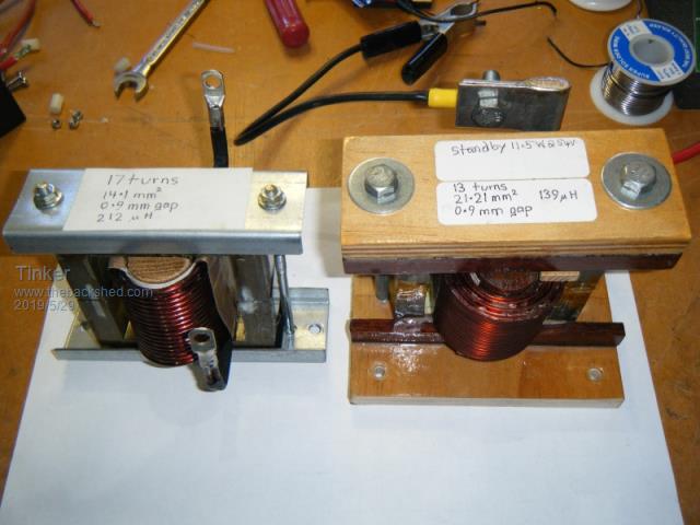 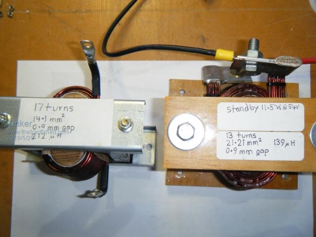 Klaus |
||||
mackoffgrid Guru Joined: 13/03/2017 Location: AustraliaPosts: 460 |
Klaus. I really appreciate those photos, choke results. Btw, what method do you use to remove the enamel? I've been using map gas and charring the enamel - cleaning it with steel wool - seems a bit cave man. Thanks Andrew |
||||
| gaspo Regular Member Joined: 25/06/2018 Location: AustraliaPosts: 65 |
With this its breeze  |
||||