
|

|
Forum Index : Electronics : Experimental sinewave inverter designs
| Author | Message | ||||
| Warpspeed Guru Joined: 09/08/2007 Location: AustraliaPosts: 4406 |
Bipolar PWM should look like two full complete sine waves but 180 degrees out of phase at 50Hz. What comes out of the bride will be two complete sine waves each of half the total final amplitude. The main feature of this is that the transformer is driven with a pair pure clean uninterrupted sine waves with very little harmonic distortion. There are none of those freakish violent phase reversals at the zero crossings. Cheers, Tony. |
||||
| tinyt Guru Joined: 12/11/2017 Location: United StatesPosts: 438 |
I forgot to mention scope captures are PWM drives to the mosfets. The 'scope is bandwidth limited so I did not have to use the RC network. I don't know what the output of the H-brige to the transformer will be with those PWM. |
||||
| Warpspeed Guru Joined: 09/08/2007 Location: AustraliaPosts: 4406 |
I noticed the 10Khz bandwidth limit. In fact that is a pretty good representation of what the transformer might actually see after a series choke has removed most of the PWM leaving only a small residual ripple voltage. The ripple will be maximum at 50% duty cycle and minimum at the peaks, just as it appears. Cheers, Tony. |
||||
| Solar Mike Guru Joined: 08/02/2015 Location: New ZealandPosts: 1138 |
That's a great idea, will try that, have just received the XR2206 and PWM modulator chips so will breadboard something up and using the battery voltage feedback to alter the 50hz modulation amplitude and thus pwm waveform. Cheers Mike |
||||
| Warpspeed Guru Joined: 09/08/2007 Location: AustraliaPosts: 4406 |
If you can create a voltage regulated PWM sinewave driver, with just a couple of analog chips, it would be very difficult to beat for simplicity. Cheers, Tony. |
||||
| poida Guru Joined: 02/02/2017 Location: AustraliaPosts: 1420 |
There is another SWPM chip used in LF inverter board design. I first saw it when Madness (or maybe someone else) pointed out the Aliexpress product that uses a totem pole driver for the gate drives. This board here: What I find interesting is this product has the facility to sync up to mains. I suppose that is what the two LEDs are for. One for inverter function (on/standby/error) and the other for mains sync. The 3 pin white connector on the top is where mains voltage to sync to is fed. Note the 2 opto-isolators, used to give good HV isolation. The chip is marked "SJNB" and "C180F21" I can't find any crystal oscillator, maybe it uses an internal osc, disciplined by mains freq? Typically for an Aliexpress listing, you get different pictures of different products, all representing the same thing that is on offer. Note the close up of the totem pole drive shows an EGS002 driver card. It also uses HY3810 switches. Anyway, mains sync function is out there. I wonder if anyone can dig up some info on the chip? 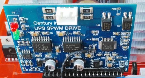 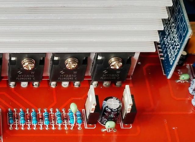 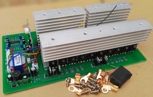 wronger than a phone book full of wrong phone numbers |
||||
Madness Guru Joined: 08/10/2011 Location: AustraliaPosts: 2498 |
I am not so sure about the mains syncing, maybe it works with EI transformers. The photo below is from a different seller of the same PCB. 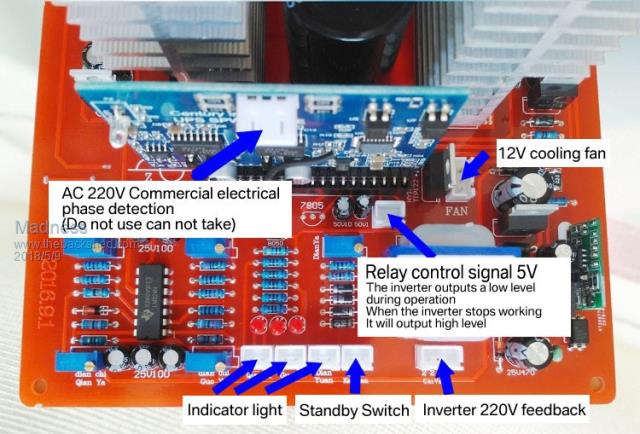 It says do not use the phase detection. Board is listed here. There are only 10 types of people in the world: those who understand binary, and those who don't. |
||||
| Warpspeed Guru Joined: 09/08/2007 Location: AustraliaPosts: 4406 |
Looking at just the pictures, that mains syncing board appears to be a direct plug in replacement for the original EGS002 board. Also, the Chinese seem to be learning from us. They are suggesting a much reduced design flux density of 1.2 Teslas for designing the transformer, instead of the more usual 1.6 to 1.7 Teslas used for normal commercial mains transformers. And they are even suggesting adding a 45uH choke to reduce idling power. Cheers, Tony. |
||||
| Clockmanfr Guru Joined: 23/10/2015 Location: FrancePosts: 429 |
Yes, the Chinese folk are no fools. Interestingly I remember 'Oztules' fitting the choke to the power Jack make of inverter and reducing the idle power used, and as I understand it within a few months Power jack were fitting Chokes. I have been watching Midnite, (USA) create its new Inverter, named after US WW2 Bombers, which as I understand it is a module type unit and as I see so far is a HF layout, (not seen any toroids yet). They reckon they have many patents applied for, but that could be just their wacky external retro design. A few weeks ago there was a Photo where they had brought in their old retired guys to sort out some stuff? Everything is possible, just give me time. 3 HughP's 3.7m Wind T's (14 years). 5kW PV on 3 Trackers, (10 yrs). 21kW PV AC coupled SH GTI's. OzInverter created Grid. 1300ah 48v. |
||||
| Warpspeed Guru Joined: 09/08/2007 Location: AustraliaPosts: 4406 |
The problem with HF inverters is that there is a very hard upper peak power limit. If it has (for example) a 2Kw switching power supply, that 2Kw is all you are ever going to get. Zero chance of briefly drawing a 3Kw surge so start up a big motor for example. Our big ugly heavy toroid inverters can produce massive short term power peaks with ease, provided there are enough mosfets to survive, which is not that difficult to do. Another nice feature is transformer inverters are bi directional. You can not only charge batteries but the inverter can tolerate low power factor loads that throw back a lot of reflected reactive power. An HF inverter cannot feed power backwards in the same way. They tend to let the smoke out with reactive loads from internal overvoltage. My current inverter is the HF type where the solar controller generates a high voltage regulated dc that then powers an unregulated stepped sinewave inverter. The only way I get away with that is having mains rectified grid power available to back up the HF inverter if it falls short of demand. All sorts of disadvantages with an HF inverter, I am surprised anyone is considering one for a new design, unless its a real cheapy. My newest stepped sinewave inverter will definitely not have an HF front end. Cheers, Tony. |
||||
| tinyt Guru Joined: 12/11/2017 Location: United StatesPosts: 438 |
I am still playing and learning from POIDA's code (pre-modified for 60Hz): To find out if it can sync on an external signal, I added the following in setup: // MOD: added the following 2 lines EICRA = _BV(ISC01) | _BV(ISC00); EIMSK = _BV(INT0); And also the following: ISR(INT0_vect) { if (pcount < 50) // Arbitrary window. { TCNT2=126; // Reset as if pcount=0; // Timer 2 overflow TCNT1=0; // happens } } I used a pulse generator set to 60Hz repetition rate and fed its output to the INT0 pin of the NANO and monitored the SPWM output of OC1A of the NANO. I get this scope capture. Yellow is pulse generator and green is the SPWM (scope is bandwidth limited). Scope is triggered on the yellow trace signal. The green trace is locked steady with the yellow trace. 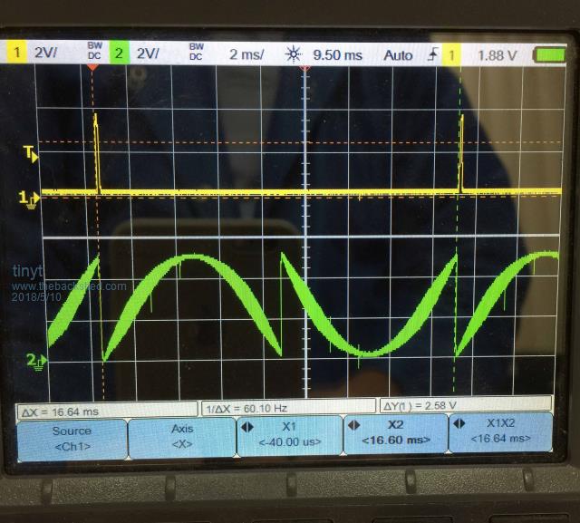 For reference, I disconnected the INT0 connection and video clip captured the scope. It shows the no sync condition. 2018-05-10_050530_OC1A_Output_NoSync.mp4.zip |
||||
| Warpspeed Guru Joined: 09/08/2007 Location: AustraliaPosts: 4406 |
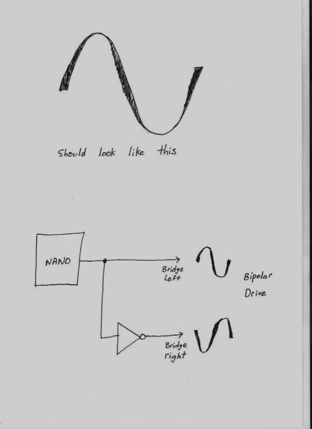 Cheers, Tony. |
||||
Madness Guru Joined: 08/10/2011 Location: AustraliaPosts: 2498 |
It changes to a normal sinewave after the choke. There are only 10 types of people in the world: those who understand binary, and those who don't. |
||||
| Warpspeed Guru Joined: 09/08/2007 Location: AustraliaPosts: 4406 |
After the choke(s) each end of the primary winding is driven by a whole complete clean unbroken sine wave that will have very low harmonic distortion. No savage violent transitions at the zero crossing points that can excite kinks or wobbles in the transformer. Cheers, Tony. |
||||
| Warpspeed Guru Joined: 09/08/2007 Location: AustraliaPosts: 4406 |
Two completely separate smaller chokes will work fine. In some cases a single larger "split" choke may be preferable, but the two windings absolutely must be connected the right way around for it to work. 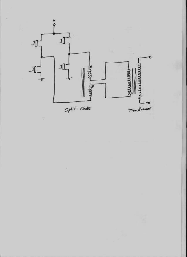 Cheers, Tony. |
||||
| tinyt Guru Joined: 12/11/2017 Location: United StatesPosts: 438 |
The code is still for unipolar. The fundamental square wave is generated by the instruction identified by '<<<<' in this code snippet: ISR(TIMER1_OVF_vect) { //20Khz SPWM long c; if(pcount == 1) // order of events is important. This gives the least time difference from 50Hz and 20kHz gate drive { // When this difference is big, larger AC output waveform distortion occurs. if (f50 == 1) cbi(PORTD,7); <<<< raise PD7 else sbi(PORTD,7); <<<< lower PD7 } c = (l[pcount] * vpwr) >> 14; // scale sin wave by vpwr 32 bit integer calcs. if (f50 == 1) // one 1/2 wave or other of 50Hz output OCR1A = c; else OCR1A = PPWM - c; pcount++; } and the 20KHz SPWM is automatically generated by '_BV(COM1A1)' in: TCCR1A = _BV(COM1A1) | _BV(COM1B0) | _BV(COM1B1) | _BV(WGM11); and enabled by: sbi(DDRB,1); The duration of the SPWM pulse is varied by the calculated value of the variable c which gets load in hardware register OCR1A. The violent transition happens when OCR1A value transitions from the variable c and the result of PPWM - c At least that is the way I understand it. |
||||
| Solar Mike Guru Joined: 08/02/2015 Location: New ZealandPosts: 1138 |
Tony is it possible to simplify the stepped transformer concept and have one main transformer with a multi tapped primary winding; switching in different tappings as required that map to voltages on the sine curve, will require more winding resistance and wire. Cheers Mike |
||||
| poida Guru Joined: 02/02/2017 Location: AustraliaPosts: 1420 |
I like it! Good to see you having fun with the code. I changed parts of it to make two 50Hz PWM sines come out of pin 9 and 10. This is following Warpspeed's thoughts of getting away from using a 50Hz square wave on one end of the bridge. The code changes: for(t=0.0,i=0; i <= NPWM; i++,t += 2.0 * 3.14159/ (float) NPWM) { u = 8192.0 * sin(t); l = 8192 + (int)u; } .. pinMode(9, OUTPUT); pinMode(10, OUTPUT); // enable OCRB1 output pin .. ISR(TIMER2_OVF_vect) { // 100Hz enable switch check, sets flag to run PID loop, ramp up etc. TCNT2=100; uf=1; if(oen == 1) sbi(PORTD,5); else cbi(PORTD,5); check_switch(); } .. ISR(TIMER1_OVF_vect) {//20Khz SPWM long c,d; uint16_t p2; c = (l[pcount] * vpwr) >> 14; // scale sin wave by vpwr 32 bit integer calcs. OCR1A = c; p2 = pcount + NPWM/2; // shift wave form table index 50% forward if (p2 >= NPWM) // wrap around the index if needed p2 -= NPWM; d = (l[p2] * vpwr) >> 14; // scale sin wave by vpwr 32 bit integer calcs. OCR1B = PPWM - d; // OCRB is compliment so we need to compliment it again! pcount++; // free running PWM now, no longer reset by timer2 OVF if(pcount >= NPWM) { pcount = 0; sbi(PORTD,7); // give a sync pulse for DSO, aligned with start of 50Hz cbi(PORTD,7); } } This gives two 50Hz sine, one 180 to the other. I must try this on the prototype inverter bridge. This code can also be modified to give a variable frequency output if desired. I wonder what would happen if I hooked the output up to a single phase induction motor and .. wronger than a phone book full of wrong phone numbers |
||||
| poida Guru Joined: 02/02/2017 Location: AustraliaPosts: 1420 |
Yes, that is correct. The reason I drive the 50Hz fundamental by code (compared with using for instance the OCR outputs) is drive the pin at the closest possible time that minimises the width of the pulse that occurs at each zero crossing point of the 50 or 60 Hz. This pulse happens because I can not have the fundamental wave transition from high/low or low/high exactly when I want it to happen. With the code I first posted in this thread, the unwanted pulse at zero crossing times is about 1.6 uSec wide. This pulse is probably contributing to - but is not the sole cause of - the output waveform wiggles. wronger than a phone book full of wrong phone numbers |
||||
| Warpspeed Guru Joined: 09/08/2007 Location: AustraliaPosts: 4406 |
This has been done, but its a very inefficient way to do it. If you have five tappings you need five sets of mosfets, each capable of supporting the full inverter load. And you only get five steps... https://www.homemade-circuits.com/simple-5-level-cascaded-sine-wave/ The multi inverter approach gives you far more steps, 27 steps for three inverters and 81 steps for four inverters. The inverters themselves see the same final load current, but the output voltages vary very widely, and so does the required power of each inverter. For example consider a four inverter design for 230v twenty amps of load (4.6Kw). Biggest inverter output 225v 20amps = 4.5Kw Second inverter output 75v 20amps = 1.5Kw Third inverter 25v 20amps = 500watts Fourth inverter 8.33v 20amps = 167 watts Only the two larger inverters are really big, and the other two fairly insignificant. Its a much more efficient way to do it. While it has a LOT more parts than a PWM inverter and undoubtedly costs more to build, its far less critical because all the switching is done at a very low frequency. The biggest inverter runs at only 50Hz. Its much more difficult to get a big bunch of parallel mosfets to switch simultaneously at 23Khz, almost five hundred times faster ! Switching times at 50Hz can be very slow, and switching losses negligible in comparison. It much easier to get going at very high power levels. With high frequency PWM, everything has to be exactly right or you will be in big trouble. Switching at 50Hz is far more forgiving. Cheers, Tony. |
||||