
|

|
Forum Index : Electronics : A newbie ozinverter build
| Author | Message | ||||
| Warpspeed Guru Joined: 09/08/2007 Location: AustraliaPosts: 4406 |
Yes, I now use screw terminal blocks for the mosfets, and driver chips in sockets. Not just for a large PWM inverter, but for any type of high power switching power supply. If it ever does go bang, I just plug in another new mosfet and another new driver chip, maybe all of them at the same time just to be sure. Which all takes very little time, and no soldering required. Zero chance of ever damaging the board no matter how many times it goes bang. Then I test the removed driver chips and mosfets independently, they either go back into my spare parts, or go out with the rubbish. The driver chip usually survives a blown mosfet perhaps about 95% of the time, but not always. This is how I built mine, its only a baby about 2Kw and it runs off 100v dc (not 48v). 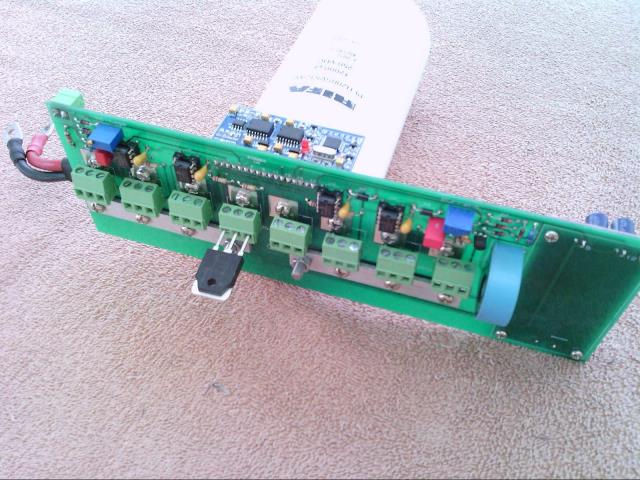 It uses a plug in EGS002 board, screw terminal blocks for eight mosfets, and four plug in gate driver chips. The two aluminium busbars bolted across the board are the dc input and ground. There is just one large low ESR capacitor, as the voltage is high and current low. The whole assembly can easily be removed from the inverter enclosure very quickly as I just did a few minutes ago. As you can see, it uses many of the ideas and improvements discussed on the Forum plus a few innovations of my own. 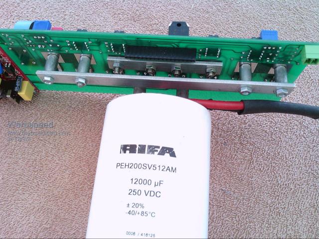 The back of the board has two more busbars that cross one above the other. These are the bridge outputs. The piggyback board on the left is a direct off line 12v and 5v switching power supply, which provides low voltage dc power for the EGS board and everything else. Its a lot bigger than it needs to be, but its something I already had and which I use for many other things as well. It was made to be very fast and simple to pull apart, for easy access and repair, without needing to use a soldering iron to replace things in most cases. Before I made a final circuit board for it, I had it running in prototype form. Pretty ugly(!) but it served its purpose. 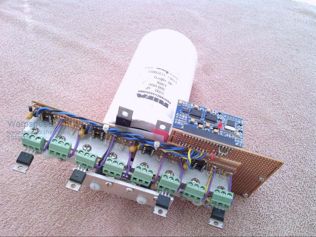 Cheers, Tony. |
||||
| Warpspeed Guru Joined: 09/08/2007 Location: AustraliaPosts: 4406 |
One other idea I had was to make the circuit board tracks absolutely indestructible between the bolted on busbars and the screw terminal blocks. I used some flat earth lugs soldered to the copper. One lug was sufficient for me, but the low voltage "big amp guys" might like to use two or three lugs soldered one on top of the other. Its pretty easy to design a new board around whatever lugs you decide to use. If you do this, the circuit board itself should never be damaged no matter what happens. The mosfet legs would violently explode long before these earth lugs even start to warm up. 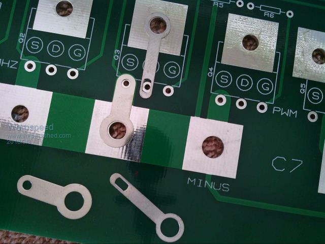 Cheers, Tony. |
||||
| johnmc Senior Member Joined: 21/01/2011 Location: AustraliaPosts: 282 |
Most impressive and much food for thought Warpspeed, Do you not use the Fet's drain heat face for cooling ? But allow heat from the FET to travel,via the drain and source legs which are screwed (fixed to the terminal blocks). Then the through the terminal block legs which are soldered to the copper earth lugs, the bus bar then acts as a heat sink ? Are the drives for the fets TC4452 gate driver chips? Cheers john johnmc |
||||
| Warpspeed Guru Joined: 09/08/2007 Location: AustraliaPosts: 4406 |
The fets bolt onto a rather large finned vertical heatsink. That takes care of all the thermal issues. In fact, the fet leads support the whole inverter circuit board, along with a large 12mm threaded stud on the end of the capacitor. The gate driver chips are TC4452's, each driving two mosfets. There is nothing really special about it electrically, but its the physical construction and layout that varies most from what most people here are doing. Its just a bit different, not necessarily better, but presented as an alternative way of doing things. Cheers, Tony. |
||||
| Warpspeed Guru Joined: 09/08/2007 Location: AustraliaPosts: 4406 |
The heatsink is bolted to a 6.35mm thick aluminium "L" angle bracket that pokes through into the inside of the enclosure through a wide slot. 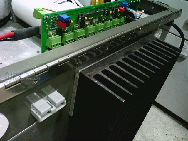 I have not put the mosfets back properly yet, but these drop over some 3mm studs and are held down with a nut onto the top of what pokes through the slot from the outside. Its all highly accessible and very easy to work on, which has been the main philosophy all along. 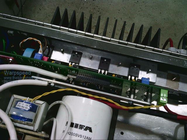 I originally proposed a hinged lid on the whole thing, with a gas strut, but a completely removable top held down with four luggage clasps has proved to be much more practical and a whole lot simpler. Cheers, Tony. |
||||
| noneyabussiness Guru Joined: 31/07/2017 Location: AustraliaPosts: 513 |
Eay Warp, microchip do a similar version to the tc4452, can be cheaper too.. FREE SHIPPING MIC4452YN MIC4452Y MIC4452 4452YN 4452 DIP8 10PCS/LOT http://s.aliexpress.com/A7fyUbeA?fromSns Ive been using them for a while and perform great.. I think it works !! |
||||
| Warpspeed Guru Joined: 09/08/2007 Location: AustraliaPosts: 4406 |
They are a nice chip to use, and the price is coming down too. Currently thee bux on e-bay. https://www.ebay.com.au/itm/1pcs-MIC4452YN-4452YN-DRIVER-MOSFET-DIP-8/172548965928?hash=item282cb84628:g:gwUAAOSwOgdYsT5 F https://www.ebay.com.au/itm/1pcs-MIC4452YN-4452YN-DRIVER-MOSFET-DIP-8/172548965928?hash=item282cb84628:g:gwUAAOSwOgdYsT5 F Cheers, Tony. |
||||
| noneyabussiness Guru Joined: 31/07/2017 Location: AustraliaPosts: 513 |
I find the mic4452s are usually slightly cheaper than the tc4452s and identical performance. . I think it works !! |
||||
| Tinker Guru Joined: 07/11/2007 Location: AustraliaPosts: 1904 |
Nice job there Tony and good to see that the "I build it my way" spirit is still alive and kicking rather than copying some Chinese layout. Some of my own observations might be helpful to other builders. I too use these Dinkle terminal blocks to connect the Mosfets. But on my PCB the heatsink edge screws directly to the board. That places the Mosfet legs very close to the heatsink which could (and did) flashover in case of a mosfet explosion. The terminal blocks do then get badly blackened, PCB cleaner got it off on most but two of the 16 required replacement. That happened some time ago at my first experiments with using terminal blocks. I have placed 1mm thick phenolic? insulating strips there (just visible in the photo behind the legs of that first Mosfet) in case it happens again but the inverter now works trouble free  . .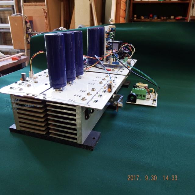 I also tried those 4452 drivers way back when experimenting with jumbo Mosfets but managed to blow the lot up. That cost me a few  as these jumbo mosfets were rather expensive. as these jumbo mosfets were rather expensive.The totem pole drivers work well for me now, even just of a 12V supply. Klaus |
||||
| tinyt Guru Joined: 12/11/2017 Location: United StatesPosts: 438 |
Awesome!! Very impressive galleries and technical knowledge. I hope I can get advice from you when my creation keeps blowing up. |
||||
| Warpspeed Guru Joined: 09/08/2007 Location: AustraliaPosts: 4406 |
Its like learning to ride a bike. You are going to fall off for sure at least once. If you wear a crash helmet and knee pads, you can laugh about it later. Likewise, build your inverter so all the expendable parts can be very easily reached and replaced, and when the smoke clears, it doesn't really seem like such a big disaster. Cheers, Tony. |
||||
| tinyt Guru Joined: 12/11/2017 Location: United StatesPosts: 438 |
Finally got the PCB designed. I started with overall dimension of 7" (178mm) x 14" (355mm) but ended with 7" (178mm) x 17" (432mm). And I still had to remove some components to make everything fit. This is top silkscreen, top soldermask and top copper. 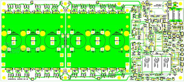 This is bottom copper and bottom soldermask viewed thru the top with the top soldermask and top copper hidden. 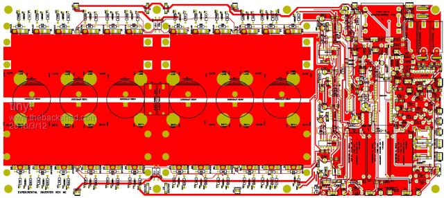 Still debating whether I place the order now or do some more schematic and PCB layout checking.  |
||||
| Warpspeed Guru Joined: 09/08/2007 Location: AustraliaPosts: 4406 |
I just usually do a fast check, and then take my chances. If I can find three errors, there will always be a fourth error lurking in there somewhere. There is always something. Maybe a hole size or a clearance. I just get the beast made, then find ALL of the things I could have done better. Attempt number two will then always be perfect. Cheers, Tony. |
||||
| Tinker Guru Joined: 07/11/2007 Location: AustraliaPosts: 1904 |
My comments on your PCB; If you have these made in China then you would be much better off splitting that into three boards. Smaller boards are cheaper You will find that the power side of the circuit is easily parted into two identical boards. These can then be made in 2oz copper for better current carrying capacity. You can see that idea in the picture I posted of my inverter above. There are minimal interconnections between the power boards since you already run separate gate feeds (good idea.) Just the negative has to connect the boards - I use a 25x1.6mm tinned copper strip for that. The positive is via the long heat sink that bridges both boards, that's it! Then your control board can be made in 1oz copper and conveniently located to suit your enclosure. Have fun. Klaus |
||||
| tinyt Guru Joined: 12/11/2017 Location: United StatesPosts: 438 |
Had some time to work on Tony's suggestion. I used J-B Weld (powdered steel filled 2-part epoxy). 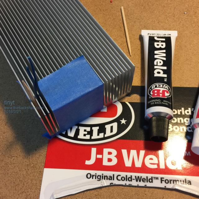 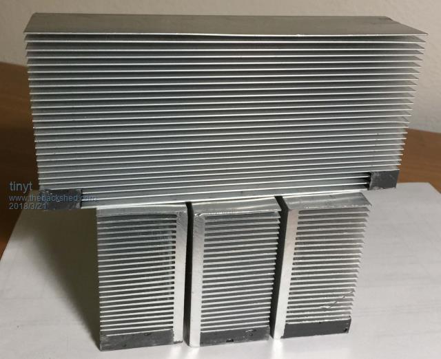 Will do the drill and tap next. |
||||
| Warpspeed Guru Joined: 09/08/2007 Location: AustraliaPosts: 4406 |
Now that is a really excellent idea. That JB Weld stuff is truly amazing !! Well done. Cheers, Tony. |
||||
| tinyt Guru Joined: 12/11/2017 Location: United StatesPosts: 438 |
The PCB came and as I expected, there were issues. Luckily, they are not show stoppers. 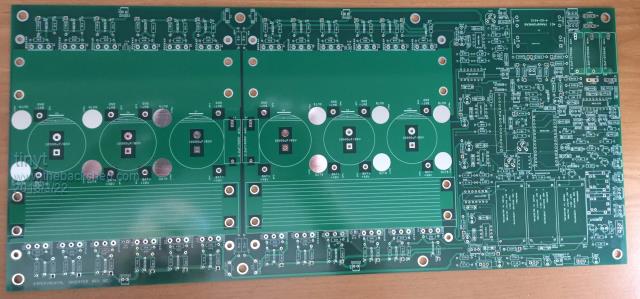 First: The holes for the cathode terminal of diodes 1N4002, 1N5817, Zeners, and FR107 are a bit large. I was probably sleeping when I made the footprints for them. They can be used as is, will just need more solder to fill the hole gap. 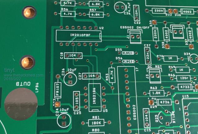 Second: The holes for the BAT+ and BAT- wires are too small for AWG #10 stranded wires. Luckily, there is no connection to the top of the PCB for each of the wire pads, so I can drill the holes (16 of them) to make them larger. 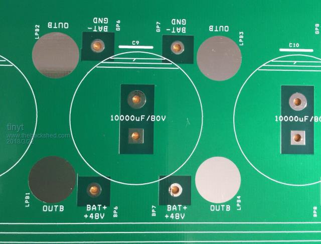 |
||||
| tinyt Guru Joined: 12/11/2017 Location: United StatesPosts: 438 |
Finally got most of the parts soldered except the power components. 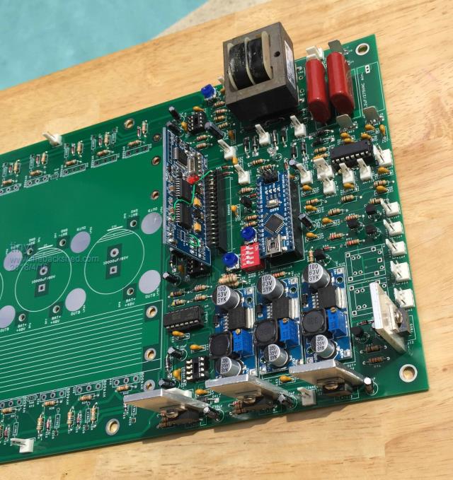 I used a bench top power supply set to 54VDC and powered the controller thru the series R78 which is 3.6 ohms (it is what I have) and measured voltage drop across it as I add components in the following steps: Step | Installed Components | R78 Voltage | Calc. Current | Calc. Watts | Delta Watts 1 3 DC-DC (LM2596HV) 0.0973 0.027 1.46 2 Linear regulators 0.1678 0.047 2.52 1.06 3 ArduinoNano 0.2116 0.059 3.17 0.66 4 MAX232 0.232 0.064 3.48 0.31 5 EGS002 0.263 0.0731 3.95 0.47 6 IR2010 0.264 0.0733 3.96 0.02 7 1 FAN (12v 0.25A) 0.52 0.1444 7.8 3.84 8 1 FAN (12v 0.25A) 1.48 0.4111 22.2 14.4 <--??? I disconnected the 2 fans and let it sit in step 6 condition for about an hour. Then I did touch temperatures on the linear regulator heat sinks and the LM2596HVs chips. The heatinks are slightly warm but the U7, and U13 chips are warmer. The U10 chip is hot. So I use a thermocouple probe and noted the following temperatures in centigrade. U7 - 48.7 U13 - 48.5 U10 - 71.7 I just found out that TI(National?) no longer makes the high voltage version of the LM2596HVS but makes a 60V 2A pin compatible LM2592HV. Will order these and swap out the LM2596HVS and see what happens to temperature and when loaded with 2 fans. |
||||
| tinyt Guru Joined: 12/11/2017 Location: United StatesPosts: 438 |
I did not change the chip. What I did is changed the orientation of the U13 DC-DC pcb to vertical. This DC-DC is for powering the fans. And it sits in between the two other DC-DCs. 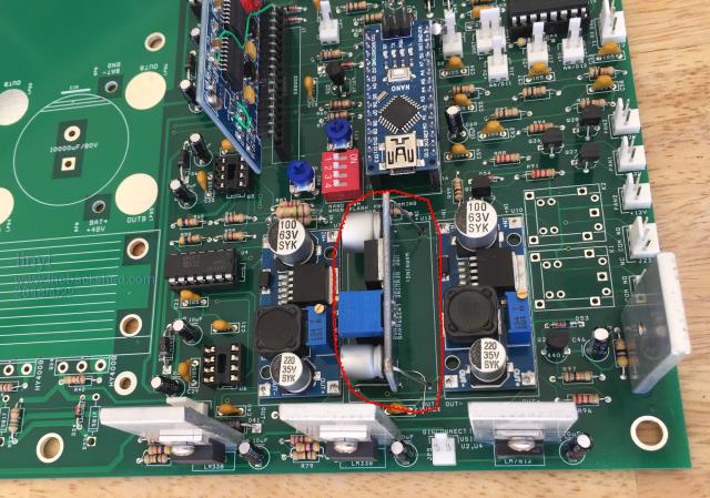 Then I re-measured. This time also I was able to add a third fan. Step | Installed Components | R78 Voltage | Calc. Current | Calc. Watts | Delta Watts 2 Linear regulators 0.1678 0.047 2.52 1.06 3 ArduinoNano 0.217 0.0603 3.26 0.74 4 MAX232 0.232 0.0644 3.48 0.23 5 EGS002 0.262 0.0728 3.93 0.45 6 IR2010 0.264 0.0733 3.96 0.03 7 1 FAN (12v 0.25A) 0.515 0.1431 7.73 3.77 OK 8 1 FAN (12v 0.25A) 0.765 0.2125 11.48 3.75 OK 9 1 FAN (12v 0.25A) 1.00 0.2778 15.00 3.53 OK Maybe some magnetic voodoo is going on, I don't know. |
||||
| johnmc Senior Member Joined: 21/01/2011 Location: AustraliaPosts: 282 |
Thanks for the update , watching with much interest, Cheers john johnmc |
||||