|

|
Forum Index : Electronics : 6Kw Ozinverter build
| Author | Message | ||||
| Tinker Guru Joined: 07/11/2007 Location: AustraliaPosts: 1904 |
Mark, you may have misunderstood *why* I have used these recycled Aerosharp cores *as well* as the ferrite E core with 4 turns on it. The ferrite core is in the HF leg of the primary to get rid of the HF hash. The choke, made from recycled Aerosharp choke cores (with a 2.5mm air gap!) is there to stop the primary saturating with a high current spike. You might get away without that, you might not - I play it safe  . .There is loads and loads of choke info splattered over various threads here, take a break and catch a quiet moment to read through it all and siphon useful info out of the various posts. Our home built inverters are at an 'experimental' stage and, as you have found out, it takes a fair bit of experimenting to figure out how to build a successful one. I did not have the foggiest idea about how an inverter works (despite my electronic background  ) and with lots of tinkering and chasing ideas posted here I have now three working inverters. The first one uses a bought board, just the toroid and ancilliary gear was home built. The other two were built from scratch. ) and with lots of tinkering and chasing ideas posted here I have now three working inverters. The first one uses a bought board, just the toroid and ancilliary gear was home built. The other two were built from scratch.So, I could assume now that I understand the basics of these things. The goal is to get to poida's expertise, but that is a long while down the track. The trip there will keep me out of mischief, perhaps. Also try to find warpspeeds posts about resonating the secondary at 75Hz with that capacitor. In my built it was 2uF that got closest, other builds might require different caps. Klaus |
||||
| poida Guru Joined: 02/02/2017 Location: AustraliaPosts: 1420 |
my wife's Sudoku puzzle wronger than a phone book full of wrong phone numbers |
||||
| Warpspeed Guru Joined: 09/08/2007 Location: AustraliaPosts: 4406 |
Mark called by this afternoon, and we did some testing... The transformer secondary resonated at 76Hz with 6uF which is pretty much ideal. Then we started looking at chokes. Mark has glued together two pairs of Aerosharp U cores with about a 1.1mm air gap. We put 17 turns of about 10mm squared test wire on that, and tested it to 70 amps which is the limit of my tester. Not the slightest sign of saturation, straight as a ruler and we measured 263uH with it like that. Next we looked at what wire might fit the choke and we ended up with 12 turns of 25mm squared which gave a measured 125uH. At 4 Amps per mm squared, it should run very slightly warm but will handle 100 continuous amps with ease. As we have reduced the turns from 17 to 12, we know that the saturation must be well above 17/12 x 70A or much greater than 99 amps. With about 125uH inductance, the peak to peak ripple current works out to 8 amps, which is pretty ideal. The whole exercise went flawlessly and everything just fell perfectly into place very first attempt. Really looking forward to how this all goes. Cheers, Tony. |
||||
renewableMark Guru Joined: 09/12/2017 Location: AustraliaPosts: 1678 |
Thanks heaps for the help today Warp. Fantastic result so far. Looking forward to putting it all together. Cheers Caveman Mark Off grid eastern Melb |
||||
renewableMark Guru Joined: 09/12/2017 Location: AustraliaPosts: 1678 |
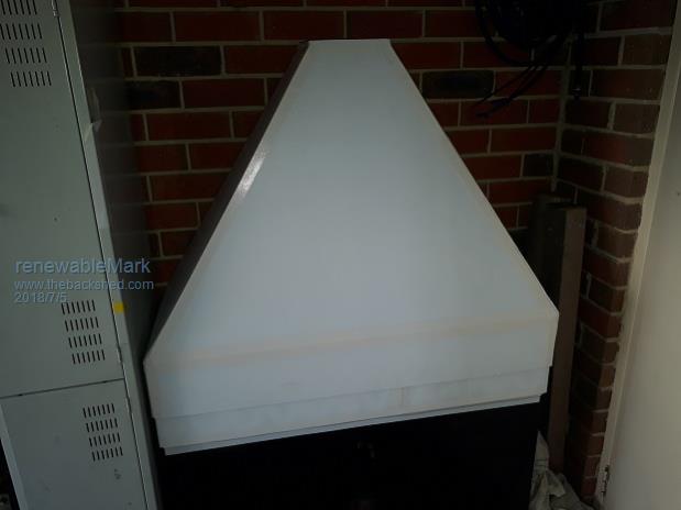
I had to finish the battery/charge setup before I can set up the inverter. As the battery is in the garage it needed a range hood to vent gasses through to the roof. Made this out of 5mm coreflute, 2400x1240mm sheets were $25 each (needed 1 1/2). Going to put 2x 120mm (2 for redundancy) fans at the top, a removable fitting for 120mm pipe on top of hood and a pipe that will go through the roof. Polyurethane'd a rubber gasket to roof ready for exhaust pipe to be fitted. Shall I have the fans running 24 hr or time them for day use only when the battery is being charged and producing gasses? Just thinking I could possibly power them with a small solar panel, that will take care of the timing for me.  Cheers Caveman Mark Off grid eastern Melb |
||||
| Tinker Guru Joined: 07/11/2007 Location: AustraliaPosts: 1904 |
Mark, AFAIK the 'gasses' produced by LA batteries is hydrogen. As this is a lot lighter than air it will rise on its own if given a chance. As long as the batteries are not in a fully sealed enclosure and the room they're in is well ventilated it should be fine with your hood having something like your 120mm pipe leading outside. You need room air + gas entering the bottom of the hood for a flow up the pipe. Not sure about a fan in that, remember, it moves possible explosive gas and you don't want anything that could generate a spark there.... Klaus |
||||
renewableMark Guru Joined: 09/12/2017 Location: AustraliaPosts: 1678 |
Yeah thanks Klaus, hydrogen does go boom big time, some of your countrymen found that out with one of their big zeppelins if I recall correctly. I haven't done an air intake yet, but will have a gravity closing flap on the inside wall. The fans are brushless so there should be no spark possible (correct me if I'm wrong there), and with 2x fans running it would clear any gasses out fairly quickly so very little would be present at any time. The vapours given off are also corrosive too apparently. Considering my wife just bought a brand spanking new car I want to be totally sure no nasties are hanging about in the garage. Cheers Caveman Mark Off grid eastern Melb |
||||
| Tinker Guru Joined: 07/11/2007 Location: AustraliaPosts: 1904 |
You can also minimise that gassing with a good charge controller that prevents excessive gassing of your batteries. No gassing on my Lithium batteries   Klaus |
||||
Madness Guru Joined: 08/10/2011 Location: AustraliaPosts: 2498 |
If you go near a large FLA battery that is receiving a decent charge your nose will soon let you know that it is safe. There is not only hydrogen but acid mist also, the charge controller you have now Mark has a vent fan auxiliary output, see pages 12 & 27 of the manual. There is also a vent fan control in the charge regulator PCB you have too. I have the vent fan turning on at 51 volts, so any time it goes above that voltage it is on. There are only 10 types of people in the world: those who understand binary, and those who don't. |
||||
Madness Guru Joined: 08/10/2011 Location: AustraliaPosts: 2498 |
The only charge controller that is going to prevent gassing is one that does not put current into the battery. When I bought my current battery last year Lithium was 4 times the price. There are only 10 types of people in the world: those who understand binary, and those who don't. |
||||
| Tinker Guru Joined: 07/11/2007 Location: AustraliaPosts: 1904 |
I wrote 'excessive' gassing Gary. While I never dealt with FLA batteries of the size you have and therefore do not know how they charge, with car size FLA batteries when they are gassing a lot they tend to be over charged - too much charge applied when they're just about full anyway. The lithium comment was tongue in cheek, I'm fully aware about their cost. I was about ready to double my battery bank capacity but $6500.- for 200Ah/ 48V delivered to Perth made me think a bit more about it  . .Klaus |
||||
Madness Guru Joined: 08/10/2011 Location: AustraliaPosts: 2498 |
Klaus you need to equalize FLA batteries also and that generates a lot of gas that does smell quite bad so gassing can't be avoided. But just normal charging results in plenty of gassing it is unavoidable with FLA. A normal daily charge for me is 5KW and more going into the battery, you can't compare it to a car battery. Without the good ventilation, Mark would end up in the divorce court for sure. My 775AH battery was under $4,000 delivered, I know people say you get to use more of the capacity of Lithium. But these forklift batteries are drained to 20% (not by 20%) every day in that application. My normal overnight drawdown is to 80% SOC I can go 3 plus days of really cloudy weather and get down to 40%. It could go to 20% but the deeper they are discharged regularly the shorter the lifespan. From the research that I have done, people are getting up to 20 years out FLA forklift batteries in solar use. There are only 10 types of people in the world: those who understand binary, and those who don't. |
||||
renewableMark Guru Joined: 09/12/2017 Location: AustraliaPosts: 1678 |
Thanks Mad, I found a video that explains it too. Cheers that's just what I need. They are a pretty smart unit hey. Cheers Caveman Mark Off grid eastern Melb |
||||
| nickskethisniks Guru Joined: 17/10/2017 Location: BelgiumPosts: 458 |
How do you let the transformer and capacitor resonate, how did you test it? Or do you just calculate it? |
||||
renewableMark Guru Joined: 09/12/2017 Location: AustraliaPosts: 1678 |
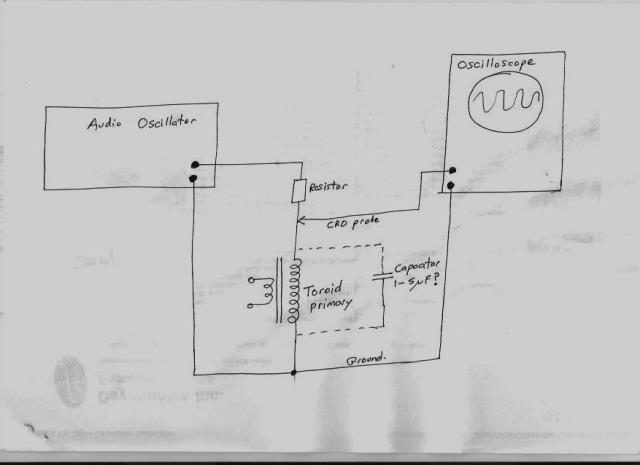
G'day Nick, Tony used a signal generator and fed it through the secondaries and looked at the wave on a cro. The wave varies as the frequency of the signal is changed. There is a "sweet spot" where the wave is at it's peak. With 7uf the frequency for my torroid was 65. 6 uf made it 76hz But my torroid will be different to every one elses, so don't just go with 6uf. Just to recap, my toroid is a dual stacked 3kw aero sharp with 128 turns on the secondary and 4 layers. Now onto the fans, I tested the amp draw and it's only 430 ma, less than half an amp. I don't think that's worth bothering to set it up on a circuit for on/off, with that little drain I may as well leave them on 24hr. Cheers Caveman Mark Off grid eastern Melb |
||||
Madness Guru Joined: 08/10/2011 Location: AustraliaPosts: 2498 |
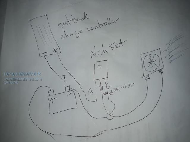
If you change your mind Mark about the fans a N Channel MOSFET with the gate connected to the + output of the charge controllers auxilary and a 20K resistor across drain and source to keep it off when it should be will work. You then connect the negative from the fans to the MOSFET Drain and the source of the FET to ground. A 12V power supply between ground and fans + and your in business. One those 48VDC - 12VDc converters will work or a 12VDC wall wart will drive the fans with no problem. There are only 10 types of people in the world: those who understand binary, and those who don't. |
||||
renewableMark Guru Joined: 09/12/2017 Location: AustraliaPosts: 1678 |
So like this yeah? Where does the neg from charge controller go?  Cheers Caveman Mark Off grid eastern Melb |
||||
| Warpspeed Guru Joined: 09/08/2007 Location: AustraliaPosts: 4406 |
Connect up the secondary through a 1K resistor to an audio signal generator, and monitor the voltage with an oscilloscope. A definite peak in voltage will be found at the parallel resonant frequency.  Cheers, Tony. |
||||
Madness Guru Joined: 08/10/2011 Location: AustraliaPosts: 2498 |
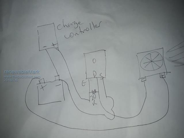
That negative wire goes to negative on the battery, the resistor goes between the gate and source not the drain as per your diagram (I just read my previous post I EFFED up, definitely gate source resistor) . The resistors job is to keep the gate at 0 volts when there is no 12V output from the CC Auxilary, otherwise, the gate will float and have the MOSFET turning on by itself. There are only 10 types of people in the world: those who understand binary, and those who don't. |
||||
renewableMark Guru Joined: 09/12/2017 Location: AustraliaPosts: 1678 |
Frigg, I can't edit or even remove the diagram above. So like this then?  Like my artistic woosh from the fan? Cheers Caveman Mark Off grid eastern Melb |
||||