
|

|
Forum Index : Electronics : 6Kw Ozinverter build
| Author | Message | ||||
Madness Guru Joined: 08/10/2011 Location: AustraliaPosts: 2498 |
I use the probe on the 10X setting and straight across the L & N of the output of the inverter, but should not matter if connected anywhere else. If you are getting 0.48A no load and a quite toroid at 2400W I would say you have cracked it and something is amiss with the CRO. There are only 10 types of people in the world: those who understand binary, and those who don't. |
||||
renewableMark Guru Joined: 09/12/2017 Location: AustraliaPosts: 1678 |
No the 0.48A was the other inverter, this one is doing 1.4A. One thing I thought of was the extra mosfets that got put in as well since last good scope result. Is there a way to test them in circuit? Will putting a scope on them in circuit show an individual one that has a fault? Cheers Caveman Mark Off grid eastern Melb |
||||
Madness Guru Joined: 08/10/2011 Location: AustraliaPosts: 2498 |
The Drain and Source of each 6 MOSFET group are hard-wired together so you will see nothing different there. You may pick up a slight differences on the gate if there is anything there but I very much doubt there is anything to see. Still think you should try the LCD CRO before doing anything else. Can you post images of what you are getting at each of the four gate circuits at the MOSFETs? There are only 10 types of people in the world: those who understand binary, and those who don't. |
||||
renewableMark Guru Joined: 09/12/2017 Location: AustraliaPosts: 1678 |
Yeah ok will do. I'll try the other control board first if no joy, then swap the red one back and test/post the signal at mosfet gates. Cheers Caveman Mark Off grid eastern Melb |
||||
Madness Guru Joined: 08/10/2011 Location: AustraliaPosts: 2498 |
It would better to to get to the bottom of it and let us see what is going on. There are only 10 types of people in the world: those who understand binary, and those who don't. |
||||
| tinyt Guru Joined: 12/11/2017 Location: United StatesPosts: 438 |
Looks like the 'scope is showing that the amplitude is switching between two fixed levels. Maybe if you slow down the Horizontal Timebase (Seconds per division?) to confirm. |
||||
renewableMark Guru Joined: 09/12/2017 Location: AustraliaPosts: 1678 |
Ok I put the Clockman control board on the Mad power board and it still did the same thing, 1.4A no load. Ran the Clockman control and power board on my torroid and it was fine, no load was 0.7A, looking back in the thread it was 0.48 but that was before caps got added. Anyway that tells us the torroid should be fine and control board also. Looks like something in the power board. I tested the gate of every fet and they all looked the same as the other ones in their sets. Pics of signals as follows. 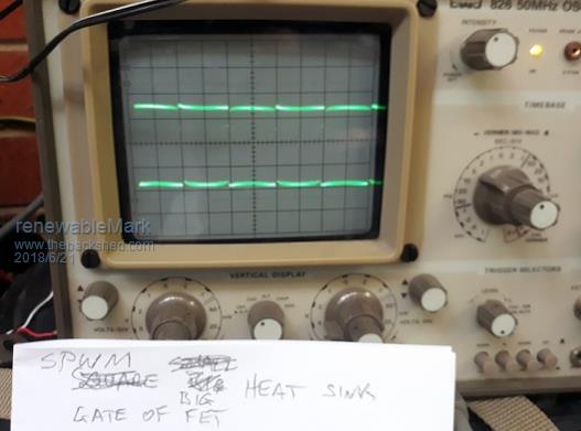 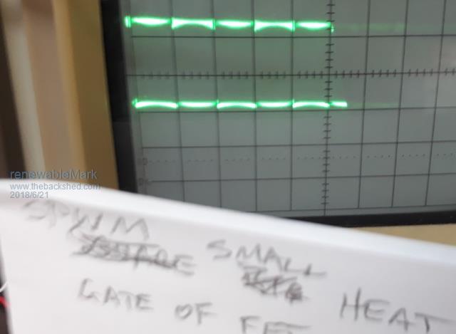 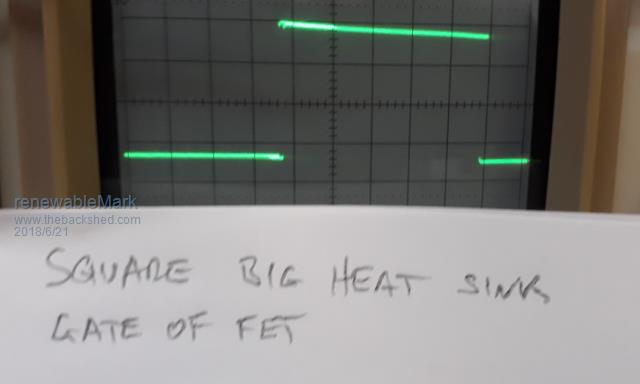 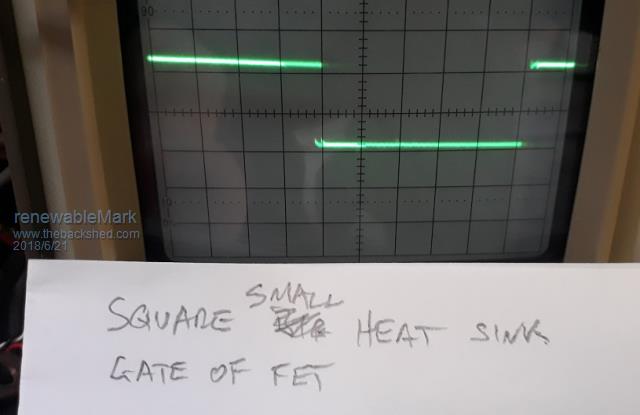 Cheers Caveman Mark Off grid eastern Melb |
||||
| poida Guru Joined: 02/02/2017 Location: AustraliaPosts: 1420 |
Mark, the the doubled sinewave trace you see on the output is related to the SPWM. The voltage of the DC bus is switched into the primary winding 24KHz. I have a nice illustration of this Pink is 50Hz output into the primary winding, Yellow is 24 KHz PWM switched DC bus voltage into the primary winding, Light Blue is primary winding current and Dark Blue is primary winding voltage. 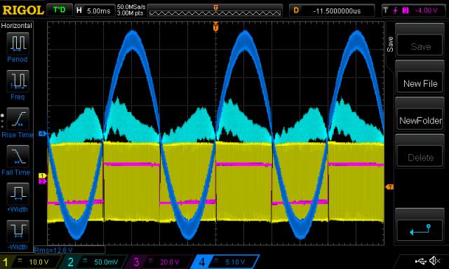 here it is zoomed in in the lower window 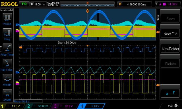 You can see clearly the inductor current increase linearly when the DC bus is switched in, and the current drop linearly when it is connected to ground. This happens at a rate of 24 Khz - the PWM freq. This results in two primary winding voltages, rapidly changing between one and another level. The DSO (digital storage Oscilloscope) of mine can capture events in time and freeze them for examination. The CRO you have can not do this and so it shows two traces superimposed on one as it were. I fed the primary voltage signal into my Tektronix 2235 CRO and I see a trace like yours. 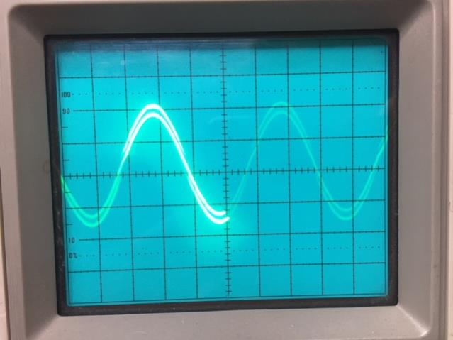 The double sinewave trace you have is probed at the secondary I believe and this indicates to me you need more inductance in the primary choke and/or more capacitor on the secondary. In all of my inverters I have built I never see the double voltage trace on the secondary. When probing these things I use a differential probe, which permits both + and - probe terminals to be any voltage, not reference to earth. In the case of your testing, I think you need to be careful to allow for the fact that the probes ground clips are connected to the 240V AC supply earth. And these are then connected to 240AC neutral within the meter box. (I can loan you my DSO and differential probe if you like) wronger than a phone book full of wrong phone numbers |
||||
| Tinker Guru Joined: 07/11/2007 Location: AustraliaPosts: 1904 |
Thanks for that info poida, I will file it for my future experimenting. It looks like my two primary chokes (one in each primary leg) do something beneficial. I have never heard about differential probes, are they an expensive must have?  On my CRO there is a switch on the back that disconnects the mains earth. Its always set to disconnected when messing with mains equipment and saves me an embarassing short via the earth clip if my brain is not in the right gear  . .I do like the idea of differential probes though. Klaus |
||||
renewableMark Guru Joined: 09/12/2017 Location: AustraliaPosts: 1678 |
Outstanding info there Poida, wow thanks mate, I was looking for a dud part. I did actually find with the laser thermometer three fets that were heating up way more than the others at idle, so replaced them. Subsequent test was expecting it to be fixed but the bloody idle went from 1.4 to 1.5A.  Earth for the scope probe is currently connected to the neg on battery. Nothing is connected to the house yet, it's set up in the garage next to the forklift battery. OK so I'll try a cap on the secondary and wind up an extra choke and see how that goes, currently it has two caps on the control board and nothing at the secondary. Fantastic, that gives me something to work on. Thanks for the loan offer, hopefully I can work it out with the info you have given me. Cheers mate  Cheers Caveman Mark Off grid eastern Melb |
||||
renewableMark Guru Joined: 09/12/2017 Location: AustraliaPosts: 1678 |
Thanks again Poida, I had to re read your post a few times to understand it. What I don't get is the Clockman inverter which was run on the same toroid and choke didn't behave the same way. For some reason this power board effects the torroid differently. Cheers Caveman Mark Off grid eastern Melb |
||||
| poida Guru Joined: 02/02/2017 Location: AustraliaPosts: 1420 |
Tinker: the differential probes I have is this set: diff probes which I bought via ebay. I bought them a while back and have got heaps of use from them due to the isolated (from ground) inputs. This permits me to connect either input to floating or changing reference points. There are situations with inverters where this is helpful. First is examining the high side mosfet gate drive. The reference level has to be the primary winding and this changes from +DC bus to -DC bus and with full battery current behind it. It would be unwise but undoubtedly spectacular to choose to connect the ground lead of a probe to this while having the inverter DC supply provided by a battery bank with negative connected to ground. Second is looking at the 240V AC output, maybe on the toroid or I sometimes look at the street power, via a wall socket. The above unit is safe for these voltages and energy levels. It provides a signal that is isolated from either input, ensuring the signal (and it's cable) is not connected to high voltage. I used them for the above post, looking at the primary winding voltage. If anybody wants to do this themselves I highly recommend you look at the voltage at the primary winding and compare it to the voltage at the mosfet bridge output (i.e. before the primary choke does it's work). It shows how much voltage changes are absorbed by the choke. Or look at the voltage across the choke. It's all educational. The 25Mhz bandwidth is more than enough for my uses. We can get the same thing using two normal CRO inputs. First you clip both channel's ground leads together. Make sure they are insulated and don't touch other energized points Then set the input attenuators to ADD and invert one or the other input. This gives the difference between the 2 inputs. I would also choose DC coupling for both inputs. Maybe some CROs have a difference mode...use that of course. wronger than a phone book full of wrong phone numbers |
||||
renewableMark Guru Joined: 09/12/2017 Location: AustraliaPosts: 1678 |
Well bugger me! I put some more inductance on the primary, that dropped the no load to 0.9A Idle hum was slightly less. Added the big cap from the Aero sharp directly across secondary and it dropped the idle to 0.75A Idle hum still there. Wave has some ripples in it at idle. wave really cleaned up with 1200w blowheater running. Turned it up to 2400w and it looked like it was trying to do that funny wave but there wasn't two separate traces, the one just looked a bit blurry at the peaks. Don't have time for photo's right now but I'll post them up later. Thanks Poida, need to find a bigger/better inductor now. Cheers Caveman Mark Off grid eastern Melb |
||||
renewableMark Guru Joined: 09/12/2017 Location: AustraliaPosts: 1678 |
Idle below 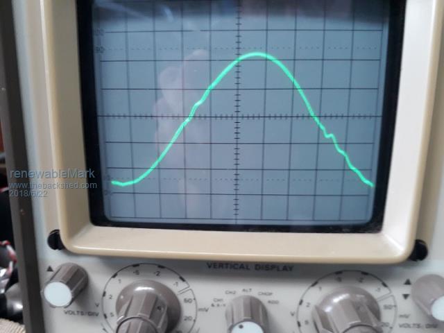 1200w below 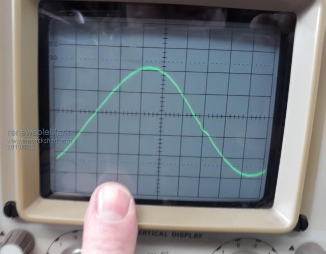 2400w below 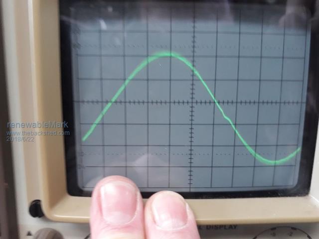 It's still too noisy at idle for my liking, when at 1200w it's almost silent. Cheers Caveman Mark Off grid eastern Melb |
||||
| Tinker Guru Joined: 07/11/2007 Location: AustraliaPosts: 1904 |
Thanks poida, for your detailed explanations and info. I did check ebay for differential probes, a bit expensive (~200.-) for my occasional use. The one at your link looks nice but no price shown, guess one would have to contact the seller. I do like your using both probes idea above, you just taught me another trick  . .I will have to try that next time I'm inverter tinkering. Klaus |
||||
renewableMark Guru Joined: 09/12/2017 Location: AustraliaPosts: 1678 |
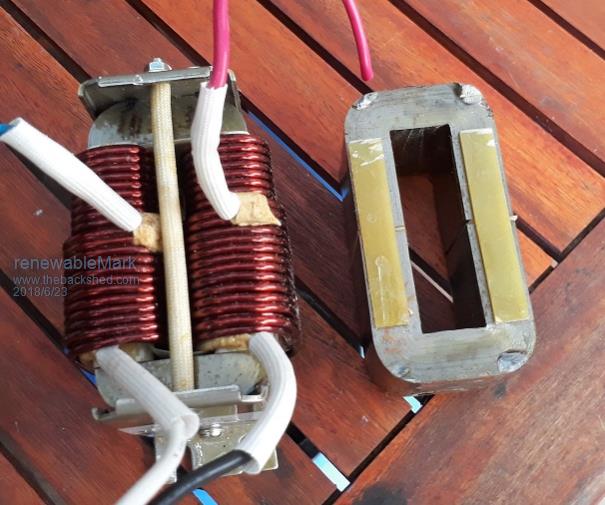 Klaus used two of these cores glued side by side and wound layers of thin copper on them and soldered the ends together. Could you instead wind on welding wire like we do with the E cores and get a decent result? Can adding more caps on the secondary be of benefit? Or can you have too much capacitance there, it would be a shame to blow the thing up now. Mad warned me about putting on too much inductance but I'd really like to try and reduce this idle hum. It does sound pretty loud and couldn't be good for it. When it had a tad more added yesterday the hum did reduce slightly. Cheers Caveman Mark Off grid eastern Melb |
||||
Madness Guru Joined: 08/10/2011 Location: AustraliaPosts: 2498 |
The easiest way for you to try different amounts of inductance is to use the e cores you have. Use a smaller diameter wire which will be fine for testing with less load and try increasing and decreasing the number of turns. There are only 10 types of people in the world: those who understand binary, and those who don't. |
||||
renewableMark Guru Joined: 09/12/2017 Location: AustraliaPosts: 1678 |
Thanks Mad, the E core can only fit 6 turns so I gravitated to the Aerosharp core as it's a lot bigger. Using just 1 core I did 10 turns and it was very quiet, sine removed the pronounced ripple but it still had some distortions, idle was 0.85A 12 turns on the same single core gave perhaps even less noise, almost silent. very similar sine wave but 0.7A. 6 turns was back to the horrible noise the E core was doing, so the two appear to have similar characteristics at idle. So assuming 12 turns on one core gave a good result, then with two aerosharp cores side by side wound 6 turns would give a similar result to one with 12 turns. Or perhaps stack the cores the way we do the torroids? 12 turn wave below @idle, no nasty blips. 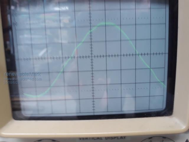 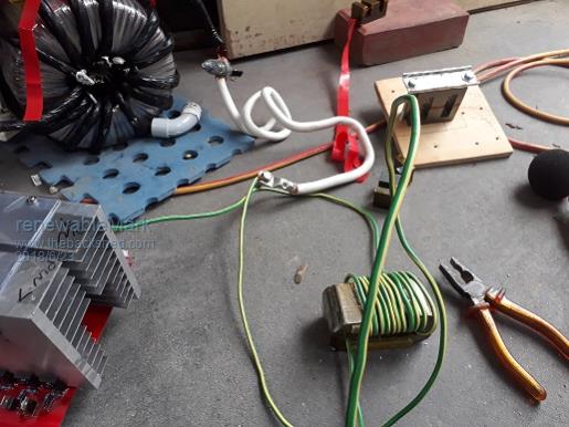 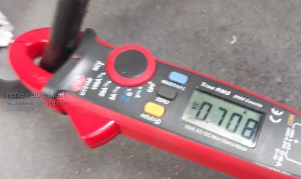 Cheers Caveman Mark Off grid eastern Melb |
||||
| poida Guru Joined: 02/02/2017 Location: AustraliaPosts: 1420 |
Mark, size is not everything when it comes to inductors. For sure, size is important when planning the conductor area and turns that need to go through a hole... But size is not the determining factor when looking at an inductor and it's function (i.e. bring some inductance to the fight) f' instance, here is a nice TDK ferrite E core with a small air gap. 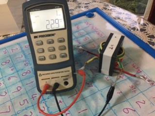 3 1/2 turns, depending how you want to count it. the LCR meter shows 22.9 uH Compare it with the Areosharp choke core with 3 turns 4.0 uH 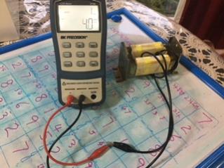 I put 6 turns in it (double the E core) and I got 10.8uH 12 turns give me 40.7uH Notice how the inductance increased by x4 when I increased turns from 6 to 12? This is to be expected. It's how things work in inductor-land. Inductance is proportional to the turns squared. I have a 6 1/2 turn winding on the E core, inductance of that is 67.4uH 67.4 uh x (3.5/6.5)^2 = 19.5, the estimated inductance for 3.5 turns when given it for 6.5 turns. I measured 22.9 so whatever. Near enough. I made a post in my thread about the E cores verses Aerosharp iron cores where I put down the 4 failures of the inverter boards to the insufficient inductance provided by the iron cores. No failures after replacing the iron core inductor with a ferrite E core Look at about 1/2 way down this page for "When 47uH is not the same as 47uH" wronger than a phone book full of wrong phone numbers |
||||
renewableMark Guru Joined: 09/12/2017 Location: AustraliaPosts: 1678 |
OK thanks Poida, well at least I tried, I thought since the good result of the wave and lower draw with almost no noise I was onto something there, but if it let's nasty frequencies through that won't be good long term by your findings. This is the one I used with 6 passes/strands through the core, but the torroid hummed too bad. I'll get another, would it be better to have two in series, stack them or makes no difference? The E core isn't that dear, I wonder why the manufacturers use the Iron type, simply cheaper? Why would it be that they don't make grid tied inverters fail, something to do with the grid absorbing nasties? Anyway, just ordered another RS one and will post results when I can. Cheers Mark BTW what is that board on the table with the numbers? Please tell it's a calculation for tattslotto numbers. Cheers Caveman Mark Off grid eastern Melb |
||||