|

|
Forum Index : Electronics : 150V 45A MPPT - roll your own
| Author | Message | ||||
| poida Guru Joined: 02/02/2017 Location: AustraliaPosts: 1419 |
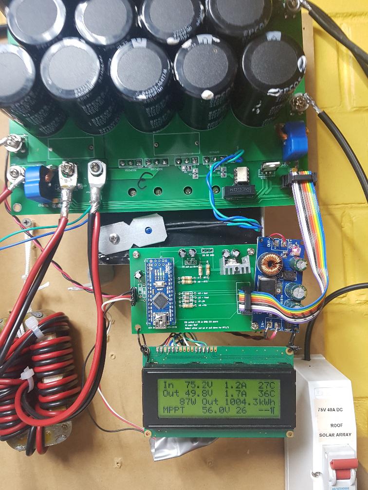
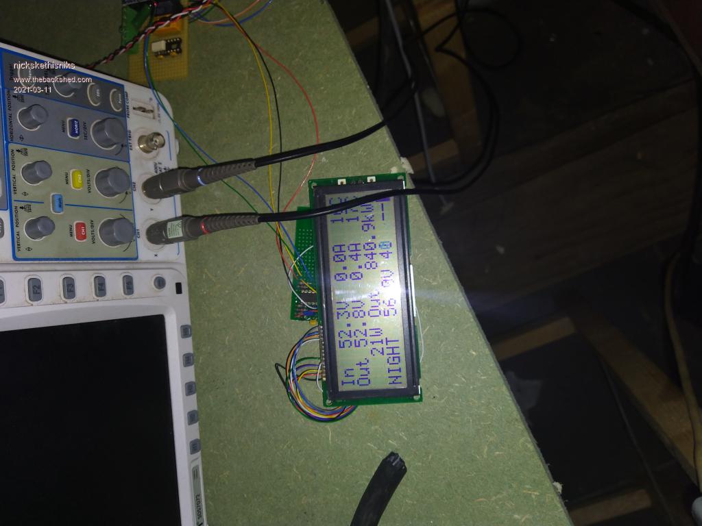
1 MW.hr It just keeps on keeping on.  wronger than a phone book full of wrong phone numbers |
||||
| nickskethisniks Guru Joined: 17/10/2017 Location: BelgiumPosts: 458 |
 Getting close to you Poida.  A bit cheating with 26 panels connected to this unit.  |
||||
| poida Guru Joined: 02/02/2017 Location: AustraliaPosts: 1419 |
Nicks: no problem with the so called cheating. None at all. I have 2 separate 3kW panel arrays. One is connected to the mppt. The other is connected to a commercial controller. I have the commercial controller handle the accurate constant voltage charge, with it's temperature sensor that can modify battery charge voltage limits that change due to temperature. The mppt (shown above) is set to do all it can up to about 1 Volt less than the commercial unit. This means the mppt does a fraction of the day's total charge, the commercial unit doing the bulk of it once the battery gets up to >55V. When I get around to it (like, what is a "roundtoit" anyway. Can I buy one?) I will retire the commercial controller, sell it for what I can get and then run two self built mppt controllers. Then I will get some good sized solar energy totals. I hope to see your system go far past mine in the next months when your Summer brings the light and for good long periods each day. wronger than a phone book full of wrong phone numbers |
||||
| flyingfishfinger Senior Member Joined: 12/09/2020 Location: United StatesPosts: 110 |
What are the latest PCBs for this? As noted in my other thread, I now have an existing inverter I can use so that's a project less this summer. However, if I'm going to have to use 48V batteries for it, that also means the BlueSolar MPPT won't cut it - that only does 12 or 24V batteries so the need for a new MPPT takes precedence (actually, two). The parts list is available (downloaded), FETs can be gotten off Aliexpress & I'm circulating phone calls for more dead inverters to harvest caps & a transformer core from, but I'm unsure which ones the latest boards are. Any pointers? Cheers, Rafael |
||||
| poida Guru Joined: 02/02/2017 Location: AustraliaPosts: 1419 |
The PCBs are designed by nickskethisniks and Wiseguy. Nicks' board is just as good a performer as Wiseguy's but WG's board looks nicer and has a better layout. Both use the same parts. I have put 3kW through nicks boards in testing. The design max current is 45 Amps. I feel I am not able to post these two designs here for free access and download since they are not mine. Rafael, I would PM Nicks or Wiseguy and ask if you could have the files. wronger than a phone book full of wrong phone numbers |
||||
| flyingfishfinger Senior Member Joined: 12/09/2020 Location: United StatesPosts: 110 |
Understood, thanks! Will do. R |
||||
| flyingfishfinger Senior Member Joined: 12/09/2020 Location: United StatesPosts: 110 |
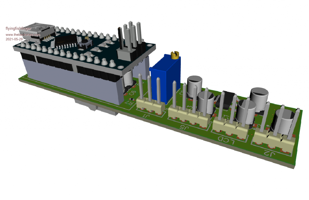
I'm making my own version of the Brainboard based on yours, Peter. I want to eliminate as many wires & pieces as possible, so I'm designing it as a "module" that mounts directly onto the Powerboard's 10-pin header. Something like this:  Couple questions though: - The trimpot seems to connect to D7, but as far as I can tell this is NOT an analog input. What's the logic? - The header that says "5V / out / GND" on D6 is for the LCD, right? - What are the A5/A4 pins for? R Edited 2021-05-29 07:29 by flyingfishfinger |
||||
| poida Guru Joined: 02/02/2017 Location: AustraliaPosts: 1419 |
Rafael, the trimpot gives a voltage for the nano's comparator. It was thought important to have some "hardware" over current protection. It worked sometimes when I tested it on the bench. Because it did not work sometimes also, I thought "right you dummy, don't short the output and it will all be OK" and not use this. The comparator uses D7 and D6 and when one exceeds the other, a status bit is set. I check this during the start of each PWM interrupt, which runs at 20kHz, and disable the PWM if set. The header provides a 0 - 5V signal from a current sensor placed in series with the inductor. I use closed loop hall effect type sensors like the LEM types and these have 3 or 4 pins, 5v, ground, signal, and sometimes a reference. If I was building a mppt now, I would dispense with these two and accept if I short the output when it's running, I will need to replace the two FETs. I like very much what you have done with this. You can now make it even smaller. Keep in mind the 12V supply, taken from the battery. For my builds I need a 60V to 12V converter. I wonder if you might want to include provision for a bit of support on the far end, to stop the board tilting in the IDC socket? D3 is used to trigger an equalisation charge program. D2 is used when you want to control the mppt output via an external controller. RenewableMark has a large solar array and wants to limit charge current from the 2 arrays and 2 charge controllers. If they are both running independently then they both could make 45A, total of 90A. But if he has a controller that can pull down D2 on both mppt when current exceeds 70A then he has the protection needed. mppt and inverters are exceedingly EMI noisy. I find the I2C system on the nano is susceptible to this and the nano can lock up - it stops running the code. If you want to use I2C for the LCD I would look at what can be done to shield the A4 and A5 pins from EMI. I instead connect the brainboard to a LCD with yet another nano that reads serial data via a digital pin. I think this is far more robust with the EMI. wronger than a phone book full of wrong phone numbers |
||||
| flyingfishfinger Senior Member Joined: 12/09/2020 Location: United StatesPosts: 110 |
This is very much a work in progress, just an idea. It wedges right between the choke return point and the 12V-12V block. I was thinking of running the choke return UNDER this board since it's tall enough. There will definitely be a support / standoff on the far end, and I'm still thinking about how to solve the 12V sourcing problem. It should be simple to implement the hardware overcurrent with an actual comparator chip separately from the Nano (which just cuts off the PWM), this is a good idea and I might add it. So you're saying the A4 & A5 pins are the I2C output that turned out to be too noisy, or did you use one of them to generate the serial signal without any library in the end? I haven't looked at the latest code yet. Totally separate question - does the MPPT finding algorithm start from a short once a minute, or the last known PPT? If I'm going to use this for a hydro generator, I can't short the wheel once a minute... Cheers, R |
||||
| poida Guru Joined: 02/02/2017 Location: AustraliaPosts: 1419 |
I used A4 for the serial signal. When I set A4 as digital out, it seems to me to then be connected to some sort of over/under voltage protection as in the other digital i/o pins. I could be wrong here. But when configured for I2C EMI can upset the device. the mppt search occurs every minute, when the battery voltage is well below the target charge voltage (i.e. absorb voltage). The search starts by ramping PWM width down to near zero from where it was prior to the search. Then it ramps it up to near 100% width stopping when - output current limit is exceeded - output power is less than that with the narrower pwm width previous - output voltage is less than absorb voltage This search takes about 3 seconds and gives us the pwm width that produces maximum output power. I call it pwm_max For the remainder of the minute, the tracking code will ensure - output current limit is not exceed - output voltage does not exceed absorb voltage - input voltage is greater than battery voltage and try to maximise output current but not exceeding pwm_max wronger than a phone book full of wrong phone numbers |
||||
| poida Guru Joined: 02/02/2017 Location: AustraliaPosts: 1419 |
picoverter BOM: This will include both NTC thermistors, one attached to the heat sink, one attached to the toroid, and give over temp protection. A DC-DC converter to give 15V. I used this one from aliexpress https://tinyurl.com/2uwe2bdf and mount it vertically. Whatever you choose needs to give 1Amp. Arduino nano IR2184 x2 LM358 LM7805 IC sockets for above 3 ICs and the nano 2 pin header 0.1" x6 1uf / 105 monolithic cap x6 0.1uf / 104 monolithic cap x6 (C22 is not needed) 10uf 25V electro x10 1uf 25V electro x2 4.7uf 25V electro x1 1N4007 diode x7 1N5231 5.1V zener x1 BAT46 diode x1 FR107 fast diode x2 LED x1 Resistors: 15K x3 4K7 x2 10K x3 100R x3 6K8 x1 1K x3 51K x1 10K NTC thermistor x2 9V AC small power transformer, taken from a wall wart, for AC voltage feedback. The 9V transformer is appropriate with a 1K for R2 The two fans: MOSFET, logic level gate voltage, IRFZ44 or similar x2 2 pin header 0.1" x2 15K resistor x2 12V fans from the stack of junk, 0.4 Amp max if using the LCD function: 3 pin header 0.1" Build notes: 15V supply is used for the gate drive output. The picoverter can drive both totem-pole type power boards as well as Madness's 4kW direct drive power board. Best results (i.e. a bullet proof inverter) are with totem-pole gate drive type power boards. R4 and R9 not important, use something >10K IC orientation is to be carefully observed. I have inverted U1 compared with U2. Get it wrong and will cost you $6 for a new IR2184 Prior to connecting the picoverter to the power board, move the trimpot all the way so that the wiper is now zero Ohms with the cathode of D7 and the lower pin of R5. This is the node where D7 and R11 are joined.  maybe use a trimpot with the vertical screw, I used what I had in the box of spares. In doing this, the AC voltage feedback will be at the maximum and so the inverter will produce the smallest output voltage it can. This is a safe way to start up the inverter when we have no idea where to put the trimpot. Later on, you can set the AC output voltage as required. (should you not set the trimpot as above, there is a high likelihood that the inverter will run to voltages way over 240V, something like 280V, and draw a lot of current due to the now well saturated toroid transformer. not good) Edit the picoverter firmware to suit your needs. Unedited code will work fine. load the nano with the picoverter firmware. The battery voltage sense resistor divider will be not quite right and need calibration. The calibration value is in the firmware and you change it thus: load the special DC voltage calibration firmware into the nano. Connect the picoverter, with this firmware loaded, to the power board. connect to the serial monitor from the Arduino program. It will print the measured DC voltage and the calibration value. It will probably be a bit wrong. At the top of the console, type the correct voltage. It will then make a new calibration value and print the voltage and the new cal value. Eventually you will get it close enough. Note this calibration value. Edit the picoverter firmware and replace the old DC cal. value with this new one, then load the firmware into the nano. Now we are good to go with using the inverter. We have set Vfb to a safe position and have correct DC voltage measurements. bv cal firmware: do not forget to set the serial monitor to 9600 baud see below of post.. latest picoverter firmware, with smoother battery voltage display pico_2_heavy_filter_bv.ino.zip Current schematic, pcb pdf and gerber: picoverter 30-5-2021.zip bv cal firmware: pico_bv_cal.ino.zip Edited 2021-05-30 14:52 by poida wronger than a phone book full of wrong phone numbers |
||||
| nickskethisniks Guru Joined: 17/10/2017 Location: BelgiumPosts: 458 |
I think the irs2186 drivers could also be used as driver it can drive 4A, maybe better to drive a powerboard without totem pole driver. I want to test the setup with a clockmanfr board I have as spare. @flyingfishfinger You might consider to use an atmega328 chip directly soldered on your PCB, ditching the nano completely for the smallest footprint. Just bringing out an ISP connection for programming, we don't need al the nano pins. Just using a nano to program it. |
||||
| disco4now Guru Joined: 18/12/2014 Location: AustraliaPosts: 897 |
Can the picoverter control board be 1oz copper or should it be 2oz copper as for the power board? Latest F4 Latest H7 |
||||
| poida Guru Joined: 02/02/2017 Location: AustraliaPosts: 1419 |
1oz copper is fine for the picoverter board. 2oz is best for the power board. wronger than a phone book full of wrong phone numbers |
||||
| tinyt Guru Joined: 12/11/2017 Location: United StatesPosts: 438 |
I think the nano program has to have a system clock of 16 MHz, so a 16MHz crystal/caps or oscillator chip has to be added. |
||||
| wiseguy Guru Joined: 21/06/2018 Location: AustraliaPosts: 1156 |
I think this was meant to be posted in "all home built solar system" ? If at first you dont succeed, I suggest you avoid sky diving.... Cheers Mike |
||||
| flyingfishfinger Senior Member Joined: 12/09/2020 Location: United StatesPosts: 110 |
Yes, you're both right. I did this long while back for other projects (actually, designed my own "knockoff" Arduino with some extra features), but it's kind of overkill here. ISP programming is a bit annoying even if using another Nano, plus it's just easier to plug in via USB and socket the entire Nano. Also, I designed this with SMT parts that JLCPCB specifically has available, I intend to get them to assemble a few directly. But when configured for I2C EMI can upset the device. This looks relatively easy to solve. I suspect it's because there aren't any 0.1uF decoupling capacitors on this board, they're good for filtering higher frequencies on power lines. The big 10uF's currently present on the analog I/O are good for smoothing but not so much for high frequency noise. I will add some in my board and hope I can get I2C working. For the overcurrent feature - you used a 3rd current sensor on the inductor leads for a "hardware" kill switch? Why couldn't the output current one be shared? How is "overcurrent" determined for the MPPT (cross-post above notwithstanding)? Regarding the 12V supply, after some thought I feel like it's best to keep the VBat->12V conversion offboard with the aforementioned modules, unless the Powerboard gets redesigned to accommodate it. It's not very practical to put it on the Brainboard. This way we can also size it as needed; in my case I'll also want 12V to drive various other things that aren't on these boards. Cheers, R Edited 2021-05-31 15:44 by flyingfishfinger |
||||
| Murphy's friend Guru Joined: 04/10/2019 Location: AustraliaPosts: 648 |
I have just read through all 36 pages of this topic (this took a while  ) but cannot find a schematic for the "brain board". Is there one available somewhere? I did see the PCB layout from which it could be traced out but if a schematic already exists.... ) but cannot find a schematic for the "brain board". Is there one available somewhere? I did see the PCB layout from which it could be traced out but if a schematic already exists....Thanks. |
||||
| poida Guru Joined: 02/02/2017 Location: AustraliaPosts: 1419 |
 ) but cannot find a schematic for the "brain board". Is there one available somewhere? I did see the PCB layout from which it could be traced out but if a schematic already exists.... ) but cannot find a schematic for the "brain board". Is there one available somewhere? I did see the PCB layout from which it could be traced out but if a schematic already exists....Thanks. Schematic_brainboard_2021-06-28.pdf anything else you need? wronger than a phone book full of wrong phone numbers |
||||
| Murphy's friend Guru Joined: 04/10/2019 Location: AustraliaPosts: 648 |
Schematic_brainboard_2021-06-28.pdf anything else you need? Thanks Poida, I remember now seeing that before but could not recall where  . .I'm looking for another project and this one looks a good candidate. Doing PCB artwork is something I actually enjoy so the boards will be my own design. No doubt there might be more questions as I proceed, especially when it gets to programming that Nano, but for now those schematics and the 36 pages of info in this thread should keep me occupied for a while. Thanks again. |
||||