
|

|
Forum Index : Electronics : Various aspects of home brew inverters
| Author | Message | ||||
| Tinker Guru Joined: 07/11/2007 Location: AustraliaPosts: 1904 |
Mark, some ferrite E cores have the middle leg shorter than the outside leg, creating an air gap which does *not* require shims. That air gap cannot be reduced but could be made wider by also placing shims between the outside legs. If the core legs are all equally long then an equal thickness shim should be between each of the 3 mating faces to create an 'air' gap. The total air gap will be twice the thickness of the shim. If you do not place equal thickness shims on those cores, the ferrite core will break when it is clamped together. Quite obvious, when you think about it  . .Klaus |
||||
| ltopower Regular Member Joined: 08/03/2019 Location: United KingdomPosts: 64 |
The smaller issue I saw was that the gap in the outer 2 faces then allowed some of the flux to leack out of the ferrite path. With a 3mm gap, rather than shim all 3 faces to 1.5mm as per Mark and what is quite standard, I was looking to see if I could pad out 3mm center and then cement/expoxy + iron powder fill the outer 2 gaps. Maybe more work than needed, was just curious about the leakage and if there was a way to avoid it. I did think a small steel plate and then thought losses plus issues. Nobody seems to sell say 1mm and 0.5mm ferrite strips as shims ? |
||||
renewableMark Guru Joined: 09/12/2017 Location: AustraliaPosts: 1678 |
Thanks, that's the way I've been doing it, Itopower had me worried when he talked about grinding the middle post. OK nothing to see here move along. Cheers Caveman Mark Off grid eastern Melb |
||||
| Warpspeed Guru Joined: 09/08/2007 Location: AustraliaPosts: 4406 |
I have never tried the parallel choke idea, but it should work, and it should balance the switching losses much better than a single choke. If we are goint to have say five parallel chokes, each will need to have five times the inductance and work at one fifth the total current. The ripple current through each choke will need to be one fifth of the total. Its the ripple current we are trying to reduce. That is the purpose of the choke in the first place. So if we make 50uH our minimum inductance for a single big choke, five chokes in parallel will each need to be 250uH minimum, and preferably more than that. We don't actually gain anything in the way of using less core mass or copper, its just the same amount of "stuff" split into five smaller pieces. For instance: Five stacked T400-26 toroids with 11 turns of 25mm squared cable works out to 63uH at 100 amps dc with a nice soft saturation characteristic above 100 amps. One T400-26 toroid with 55 turns of 5mm squared cable works out to 317uH at 20 amps. Five of those in parallel we end up with the exact same 63uH at 100 amps. The bigger choke will have a lower copper loss because the length of the turns will be less to go around five stacked cores than to go right around five individual cores. Core heating should be less with five individual cores, because stacked cores have less exposed surface area. I dunno... six of one half dozen of the other. But the modular approach of five separate bridge output stages and five chokes would make for a much cleaner high frequency layout, and all the current paths would be lower. Cheers, Tony. |
||||
mackoffgrid Guru Joined: 13/03/2017 Location: AustraliaPosts: 460 |
Guys, this thread just keeps on giving  I like modular design, often not cheapest approach - on paper, but can simplify further design down the road. While I currently don't need the big chokes, I may do with future power supplies. I find the idea of winding on smaller cores at lower current ratings: Easier on increasing arthritic joints. Easier to find the parts on hand. Easier to buy from China or where ever and freight it here. my two bobs worth Andrew |
||||
| wiseguy Guru Joined: 21/06/2018 Location: AustraliaPosts: 1156 |
After Poida mentioned the inefficiency of running a big inverter all night I have been considering a couple of schemes for reducing Inverter idle power at night and possibly also during the day, mainly for saving energy capacity when there isnt much sun. If the voltage could be turned down from say 240V to 220V when less than 500W is drawn for say 5? minutes does anyone have any feel for the idle power improvement? If a larger load is sensed we could just go back to full power for a while? The second approach is a bit different, and a bit more complicated & involves a smaller say 1kW Inverter & Toroid. If the 2 inverters were coupled (summed) by solid state relays to the load but the 1kW output was set for 230V the larger for 240V then the smaller inverter would not commutate its output to the load. The operation would be as follows, big inverter running, small inverter off. Big inverter sees less than 500W for time period and just before signing off, smaller inverter is enabled along with its solid state relay drive. Large inverter commanded to soft stop and small inverter automatically picks up load as larger inverter output falls, large inverter solid state relay turns off, now we're running on small inverter. Going back to full power is similar but in reverse A nagging question is when a fridge starts or similar, does the big inverter need to start or could the smaller inverter handle the few cycles of a compressor start requirements? Any feeling for the battery capacity that might be saved with either of these schemes or is it all just a crazy idea ? If at first you dont succeed, I suggest you avoid sky diving.... Cheers Mike |
||||
mackoffgrid Guru Joined: 13/03/2017 Location: AustraliaPosts: 460 |
Mike, I reckon as long as your FETs are large enough you'll be right, a bit of sag won't matter. |
||||
| Solar Mike Guru Joined: 08/02/2015 Location: New ZealandPosts: 1138 |
Lowering standby current requires less mass of iron in the main transformer, perhaps achieved as per dia below, keep existing H-Bridge and parallel a low powered transformer, selected by a low resistance electronic mosfet switch. Because the output winding of both are always connected both transformers will be magnetized, so switching between them should be no problem ??? Cheers Mike |
||||
| Warpspeed Guru Joined: 09/08/2007 Location: AustraliaPosts: 4406 |
I cannot see that working properly as drawn. The 500w transformer is still driving the 3Kw transformer core (and its magnetising current). You would need to switch both primary and secondary of the larger transformer together. Cheers, Tony. |
||||
| Solar Mike Guru Joined: 08/02/2015 Location: New ZealandPosts: 1138 |
Of course, scrub that idea then, with the unused transformer totally out of circuit there would have to be a soft start mechanism in any changeover or just prior to the changeover. Mike |
||||
| poida Guru Joined: 02/02/2017 Location: AustraliaPosts: 1418 |
This is the scheme implemented by Victron in the 3000VA multiplus inverter I had for 2 years (plus one month. Then it died.). Instead of a large and small toroid, they used two 1/2 sized toroids of the same size. When the load was sensed to require it, both toroids were switched in to service. And when the load dropped enough, one was disabled. wronger than a phone book full of wrong phone numbers |
||||
| Warpspeed Guru Joined: 09/08/2007 Location: AustraliaPosts: 4406 |
I still believe the best way to reduce no load current is by fabricating an inverter transformer yourself, that has a very low flux density, ideally at 1.0 Teslas or less. I have a 4.5Kva inverter transformer that weighs 51Kg and has only 20 idling power watts. The commercial inverters are just too cost sensitive to ever do that. Anything else is fraught with problems and limitations. Cheers, Tony. |
||||
| ltopower Regular Member Joined: 08/03/2019 Location: United KingdomPosts: 64 |
Thought I needed a picture to explain the inductor arrangement, does the transformer in this case not decouple the inductance from being parallel ? 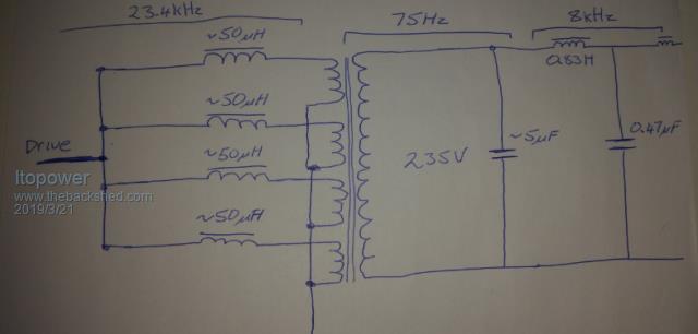 |
||||
| wiseguy Guru Joined: 21/06/2018 Location: AustraliaPosts: 1156 |
Was your original design for a single choke 50uH ? If so the 4 chokes should be 200uH x 4 off ? I reckon they should share fine in that arrangement. If at first you dont succeed, I suggest you avoid sky diving.... Cheers Mike |
||||
| ltopower Regular Member Joined: 08/03/2019 Location: United KingdomPosts: 64 |
Original was for a single 50uH choke, but struggling to sort out something practical that could support well over 100A... closer to 200A... The stack of 5 x T400 are an option (one on the way to have a test, along with 6kg of 2mm copper...), would need 10 for 200A. With 3mm gaps in the E70 chokes 47uH should get over 45A each.. but I'm not certain how much decoupling the transformer windings provide to the chokes. Still to test the actual turns for my transformer.. The E70 would need approx 24 turns (2 in hand 2mm, approx 45% window use, 30A) for 200uH and the per choke saturation dropps to around 22A, so only around 90A total. I get the about the same amount of stuff, to a degree, as I was looking if decoupling or any isolation can happen. I would be better off putting all the E70 chokes in series with 6 turns or stacking them. (I'm learning Tony, honest !) I have the E70's arriving Monday so they will be my starting point and should get me to the 5kVA level (5 pairs stacked) for 100A (95mJ each)... something does not seem right though. Will be performing quite a few tests next week if the other parts turn up. With each chokes connecting to a separate isolated winding my thought was they would decouple.... at least to some degree ? The use of a gapped steel core seems appealing (smaller), but I remember the earlier tests showing the resulting over and undershoot, unless a ferrite in series then filters the over under.. on that note, over, under, under, over and out... airplane for those left out on takeoff.. |
||||
| Warpspeed Guru Joined: 09/08/2007 Location: AustraliaPosts: 4406 |
Just suddenly realised to my horror that there are two sizes if T400 cores. There is the T400-26 that is 16.5mm tall, and the T400-26D which is double height and 33mm tall. I based all my calculations on the double height cores. Five of those would be 165mm tall. So it may require ten Chinese cores if they are the skinny ones, as I now believe they are. Sorry about this guys, I have the T400-26D cores already marked in my data book, as I have used them myself before, and overlooked the fact that they are the double height ones. Cheers, Tony. |
||||
| Warpspeed Guru Joined: 09/08/2007 Location: AustraliaPosts: 4406 |
I doubt if there is going to be any huge final difference between ferrite, powdered iron or steel. They are all going to be pretty large and heavy pieces to support a 5Kw inverter, and all can be made into something that can do the job. If we can get the high frequency PWM ripple current down low enough that we are not going to have any skin effect or eddy current problems in the main transformer, we are not going to see those problems in a steel cored choke. Both are in series and see the exact same dc+ac current and operating conditions. The big difference will be in the cost of the three materials if you have to buy the parts new. Cheers, Tony. |
||||
| BenandAmber Guru Joined: 16/02/2019 Location: United StatesPosts: 961 |
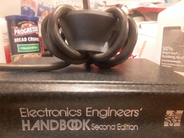 How about the ferrite material on the back of old television tubes it is quite big but a little bit odd shaped you could put two of these face to face and have a pretty big toroid shaped ferrite I am very poor so I have been trying everything  be warned i am good parrot but Dumber than a box of rocks |
||||
| poida Guru Joined: 02/02/2017 Location: AustraliaPosts: 1418 |
Part 29: Power factor This will be looking at a few devices I connect to the output of the test inverter. We will be looking at the AC current these devices draw, as well as the AC output voltage wave form. Lately, we have had some discussion about the poor waveform Mark is getting when he connects his large inverter type air con to the home power circuit supplied by his home brew inverter. here is the CRO display of his AC output voltage He sees the perfect sine wave transform to some ugly 'orrible thing when the aircon runs at middle power levels. I think I know what is going on. A pure resistive AC load is a resistor, with no capacitance nor any inductance. It is a constant resistance for the entire waveform. The best pure resistive load is a hot water heater element. It is a resistor. It has no inductance of significance, no capacitance of significance. It is a constant resistance. Some loads we apply to the house AC supply are purely resistive, such as incandescent light bulbs, electric oven or cooktops (non inverter type!) and others. When we examine the AC voltage waveform, we see a nice undistorted sine wave. This as as we think it should be. Always. But we need to realise that a lot of loads are not purely resisitive. Switch mode power supplies frequently are very uneven in their current draw, over a waveform. Same for inverter type microwaves (I guess) and the inverter powered AC brushless motor in my pool pump. I'm sure most household things like TV, computer, modem, printer, media centers, xbox etc. are to some degree uneven in the current draw over time. First let's see my unloaded AC output waveform of the test inverter. This time, I am using the nanoverter drive board and Madness's power board. DC supply is 56V Dark Blue is AC voltage Light Blue is AC current, measured at the output 240V wall socket on the bench. 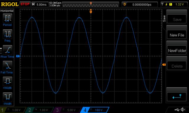 Above is a nice clean sine wave. Unloaded too. Next, we apply the load of my UPS that supplies power for the old iMac I use as a desktop computer. So this is the load of the UPS plus the iMac. UPS is an APC Back-UPS RS 800, Imac is a 24" 2007 model. 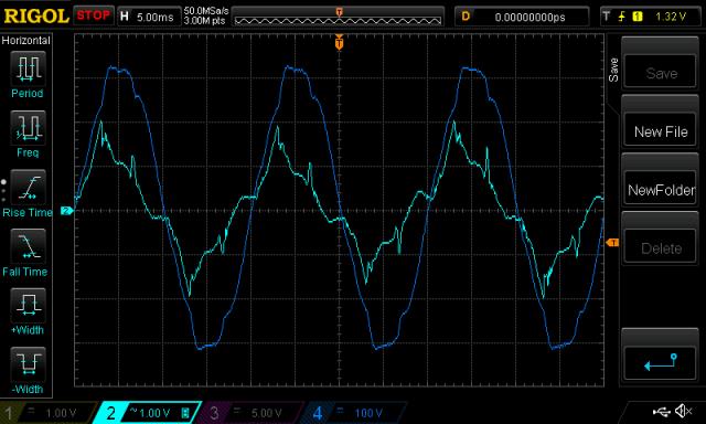 Things to notice are: The wave form of the current seems to lead a bit and has some sudden peaks here and there. And the AC voltage is now distorted. The deviations from sine wave seem to occur where there are large sudden peaks in AC current. Hmmm... Now we see when I hook up the 60W macbook power supply to the inverter output, and have the macbook open and running. 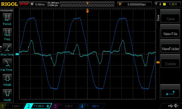 Again we see peaks in current corresponding with deviations from pure sine wave shape. In this case, the current peaks occur at near max AC voltage, and this flattens the AC voltage to some extent. Lastly, we see a old crappy Dell laptop and it's power supply. 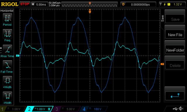 Again, deviations from ideal AC waveform shape correspond to large changes in AC current. I could show you the current when I power my standard 150W incandescent light bulb load but it would be boring, just two nice looking sine waves. (why? it's a purely resistive load) Power factor is an electrical engineering area that attracts plenty of money and effort. Mark has an issue with his inverter output AC voltage waveform when running the inverter type aircon of his. I think this is normal for this application and can not be reduced much if at all, and I doubt there is any value in attempting to reduce the distortions anyway. I suspect his aircon when operating such that it distorts the waveform is drawing large pulses of AC current, to power the high voltage DC bus of the inverter drive. This pulse type characteristic is unavoidable and needs to be accommodated in our designs. That is, ensure the home brew inverter can deliver these high current pulses indefinitely without self destruction. I suggested to him to consider a large choke on the AC side, near the aircon supply takeoff point. It would need to be big, something like 100A at 240V AC RMS (325V Peak). This is a big choke. We both did not like that idea. Maybe make a bigger, huge inverter, capable of massive current supply on the AC output? Yes, you will probably get a cleaner AC voltage waveform. But why bother. Lots of expense and work too. Anyway, I know the waveform of my home inverter is not real great and I accept that. Lots of switch mode power supplies running 24/7. Here is what it looks like right now: 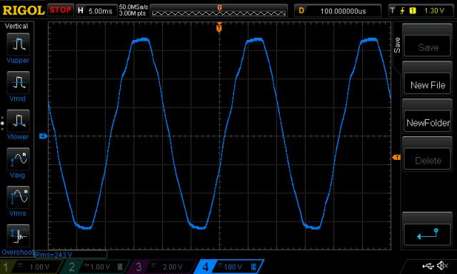 It's been like this for years. wronger than a phone book full of wrong phone numbers |
||||
| Warpspeed Guru Joined: 09/08/2007 Location: AustraliaPosts: 4406 |
All very true, and very important to understand. I think it was Madness that first discovered that we could feed 230v ac from a grid tie inverter backwards through our Oz inverters to charge the main battery ? Trying to understand how that actually works with PWM is a real mind bending exercise, but it can definitely be demonstrated to work. But I am still not absolutely certain in my own mind exactly HOW it works. As Poida has pointed out above, many types of loads can be very non linear, or highly reactive, and that can place some rather unusual stresses on an inverter. The load can not only change drastically at different parts of the ac cycle, it may bear no relationship to the voltage waveform. We can have power (current) shuffling back and forth, one moment the inverter is trying to drive current into the load, at a different part of the ac cycle current is surging backwards into the inverter in the opposite direction. That can really murder our nice clean sine wave voltages shape. Not only that, the voltage feedback may get terribly confused by the grossly distorted voltage waveforms. Its a hugely complex problem, and there is no simple solution guaranteed to fix it in all circumstances. It really comes down to the inverter and load characteristics being incompatible. Its also the one single issue that put me right off PWM inverters originally. The stepped waveform approach has two very powerful advantages when driving really nasty loads. The four inverters are completely bi-directional and with a continuous very low impedance back to the dc supply rail. The four inverters output individual square wave voltages that either add or subtract to generate the final sine wave voltage. Power is shuffling back and forth continuously (by design) even with a simple purely resistive load. If you hang a highly non linear or reactive load on the output, each individual inverter will go on quite happily generating clean square wave voltages, and sine wave currents, or chopped up sine wave currents flowing in either direction. Its doing that anyway, and it will just do it all a bit differently to accommodate a really nasty load with minimal distortion of the voltage output waveform. It does that because the transformers are switched at very low impedance direct onto the dc power supply, and provided the electrolytics on the dc side can hold a constant clean dc voltage with minimal ripple or spikes, the ac output waveform of the whole inverter will remain clean and with minimal voltage distortion. A second advantage is that there is no voltage feedback to get confused by drastic waveform distortion. Not that there should be any drastic voltage waveform distortion anyway with a step inverter. But its one less problem to worry about. Not saying its the absolute solution to all possible problems, but its a LOT more robust than PWM where the loads are really awful. Cheers, Tony. |
||||