
|

|
Forum Index : Electronics : 150V 45A MPPT - roll your own
| Author | Message | ||||
| poida Guru Joined: 02/02/2017 Location: AustraliaPosts: 1420 |
Mark, I am ordering some 200V and 300V diodes. I like the STTH6002CW and STTH6003CW from STM. I want to examine reverse recovery and forward recovery times and compare with the HY5110 to get an idea of what to expect. The 200V diode is $7.80 each and the 300V is $5.80 wronger than a phone book full of wrong phone numbers |
||||
| wiseguy Guru Joined: 21/06/2018 Location: AustraliaPosts: 1156 |
Some considerations for selecting suitable Diodes. The STTH6002CW should generate ~10-15W less heat at 40A compared to the 6003CW. I would expect the Schottky diodes of Marks to have low to almost no reverse recovery time. My understanding of the schottky barrier diode is supposedly a direct Metal to "N" junction, as there is no "P" & "N" materials there is no depletion layer formed so carriers dont have to be "swept" from the junction meaning no recovery time. Edit: All Schottky Diodes at Digikey are listed in 3 flavours: Either "-" "5nS" or "<=500nS" Most data sheets have no information on "recovery time"? I have no idea where they get their listed recovery times from. There is no need to go higher in Voltage than 150V for the Schottkys they can swallow small transients with ease The Diodes Mark has, have a repetitive avalanche rating of 31.8kW. That means if they start to avalanche at 160V they can swallow 200A transients for a microsecond repetitively, or 500A non repetitively. The Mosfets being used are 150V rated, so there really is no need to go higher than 150V for a good Schottky or 200V for an Ultrafast. Going higher than 200V usually puts the ultrafast diodes into the next higher Vf conducting category which is typically 0.4 to 0.5V higher at their rated current, generating needless heat. Edited 2020-08-26 09:27 by wiseguy If at first you dont succeed, I suggest you avoid sky diving.... Cheers Mike |
||||
| poida Guru Joined: 02/02/2017 Location: AustraliaPosts: 1420 |
The 200V 60A diodes arrived. They are STTH6002CW dual diodes with the center pin being the cathode. I will compare them with the HY5110 as a diode. 103.5V input, 1800W output into 45V Without a 0.5nF/10 Ohm snubber from switch node to DC + input and without it. Yellow is switch node voltage Purple is DC input Light Blue is pwm control into the TLP250 First we see no snubber and HY5110-as-didodes 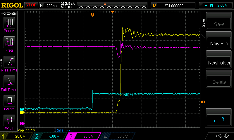 not too bad at all. Now with the RC snubber 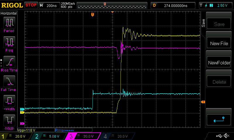 I retained the snubber and installed the 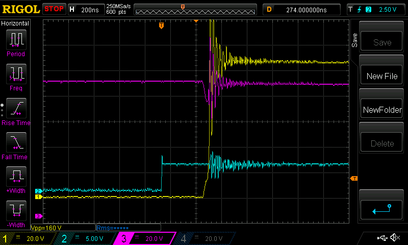 Now that is unexpected. I thought it would be a smaller spike, and not very long lived oscillation. This is not very good. Last is the Yellow trace re-scaled to 50V/div And it combines many traces so we can see the sort of average behavior of this thing. 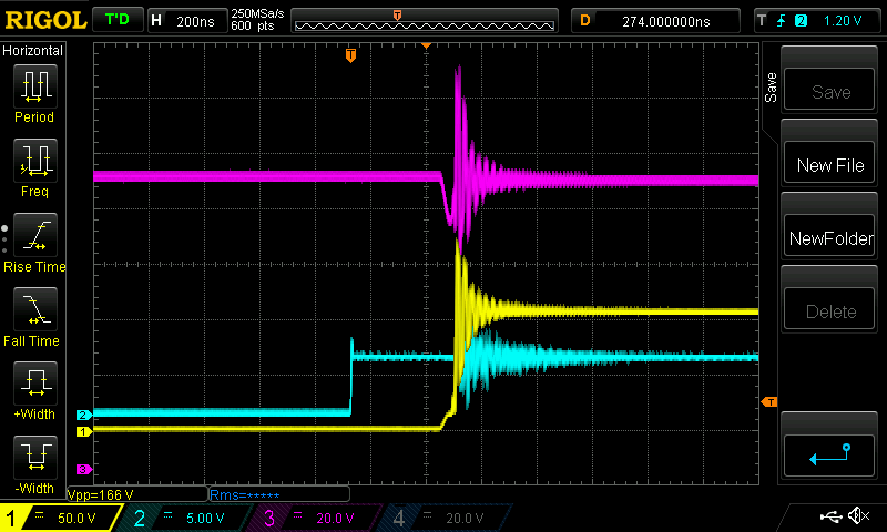 peak voltage exceeds 170V. Having the HY5110 in place seems to tame this wild voltage oscillation but probably at the cost of over volting the HY5110 body diode, which goes short circuit for voltages over 118V I am thinking I will stick with the HY5110-as-diodes and of course use the nice FDH055N15A MOSFETS for the switching job. I won't bother doing this test on Wiseguy's power board, I expect near identical results. wronger than a phone book full of wrong phone numbers |
||||
| nickskethisniks Guru Joined: 17/10/2017 Location: BelgiumPosts: 458 |
I'm almost there to test, but I got interests in another forum (https://diysolarforum.com/). I’m trying to communicate with my fancy valence saphion lifepo4 batteries for years with my own µC without any luck, now there are a few on the other forum that cracked the communication protocol. So I’m a bit desperate to try out (but need to spent a few days to adjust the code to work on my µC and RPI). There is always something getting in the way…. But, since my order is taking so long(I ordered parts with lcsc) and apparently I had components on backorder,  So I did order with TME some other components, I ordered the diodes with lcsc you are using, the 200 and 300V ones. So I did order with TME some other components, I ordered the diodes with lcsc you are using, the 200 and 300V ones. But now at this moment I only have to test with: Diodes: RURG3020CC Mosfets: IRFP4868 (300V 70A 517W) IRFP4668 (200V 130A 520W) IXFH110N25T(250V 110A 694W) I don’t know yet about the configuration, but planning to install 10 panels (280W) on this HV controller. But the shed is shaded, so ideal would be to run 2S5P. But on the moment there are only 6 panels up, waiting on brackets to mount the others. So 3S, 4S, 5S are options at the moment, because I still have to much energy. So this will be my test setup for this controller, I will need to reroute the cabling. I think I start building a controller with the IRFP4668, I think I want to use the higher voltage fets with 300V diodes. |
||||
| SYM-1 Regular Member Joined: 18/10/2019 Location: New ZealandPosts: 45 |
peak voltage exceeds 170V. Having the HY5110 in place seems to tame this wild voltage oscillation but probably at the cost of over volting the HY5110 body diode, which goes short circuit for voltages over 118V I am thinking I will stick with the HY5110-as-diodes and of course use the nice FDH055N15A MOSFETS for the switching job. I won't bother doing this test on Wiseguy's power board, I expect near identical results. I find the 170V oscillations disturbing. Sure the HY5110-as-diodes may solve the problem but can they take the stress long term? It seems to me there is a stray inductance problem that is begging to be discovered and solved. Persistence is the key |
||||
| poida Guru Joined: 02/02/2017 Location: AustraliaPosts: 1420 |
SYM-1: here are two pdfs I find most educational on ringing. H2PToday1803_design_TexasInstruments_Part 3.pdf and a practical worked example AN045_EN.pdf here are the gory details: 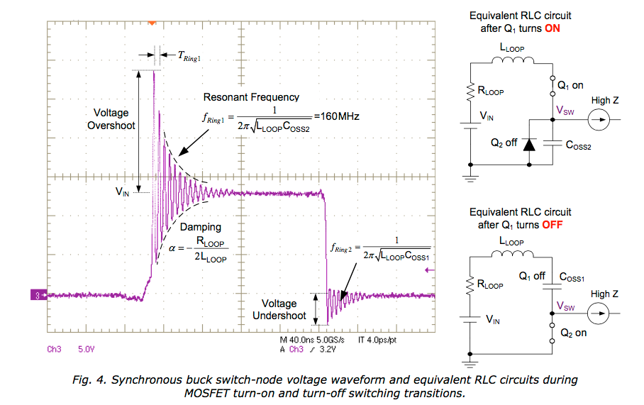 Coss2 is the diode capacitance. I suspect the HY5110 has a lot more and so when in circuit the ring frequency is a lot lower. But maybe the Q factor is lower so it does not ring so much. wronger than a phone book full of wrong phone numbers |
||||
| hugocamaras Newbie Joined: 12/04/2019 Location: BrazilPosts: 24 |
Hi Mike! Is this pdf Sketches the layout of the temporary plate? Are you going to make Gerber files available so we can reproduce the project for free or are you just going to sell the finished boards? I am following the project and would also like to assemble ... it turns out that it is complicated to buy ready-made plates from outside the country. Here is Brazil. Hehehe |
||||
| wiseguy Guru Joined: 21/06/2018 Location: AustraliaPosts: 1156 |
Hi Hugo, the final layout for the PCB have altered slightly from the "sketch" and schematic. I am considering sharing the Gerber files with you but I have a small issue that I will describe. I designed the PCB gratis for the forum to take advantage of, this was not a money making venture. I am unsure how you could turn those gerbers into a pcb with any sort of economy though. Poida had the first lot made & the cost for a brain board and the power pcb together were ~ $15 + postage. If you are planning to order in quantity you either need a sales outlet or a lot of mates who want one. I must admit, it is the sales outlet part that troubles me. If anyone was going to make these for any sort of profit it should be shared with Poida and myself  who have invested a considerable slab of time to create the project. who have invested a considerable slab of time to create the project.Please post how you intend to use the design and create PCBs in a small? quantity with any sort of economy to help me make a decision - please dont be offended. I initially ordered two of the sets from Poida and would consider selling you a set, but I would not want to send it for a few weeks in case I damage the one and only PCB I have and will be doing experiments with. Maybe someone else on the Forum has a spare set they would be happy to negotiate with you. If at first you dont succeed, I suggest you avoid sky diving.... Cheers Mike |
||||
| wiseguy Guru Joined: 21/06/2018 Location: AustraliaPosts: 1156 |
At the risk of proving myself wrong publicly, I am building up a power PCB to hopefully solve the ringing issues. I dont disagree that the papers that Poida referred to re ringing issues with regard to how to calculate the loop components that set the frequency of the ring are determined. Nor with how to calculate a snubber to "stomp" on the ring. It is what starts the ring to occur in the first place other than fast edges. I am well aware of ringing when something turns off fast and there are stray L & C that creates a decaying "ring". But the issue we are looking at is at the leading edge when the choke node is set high (FET first turned on). I have never seen a switch that switches a node to say 100VDC that rings when the switch is turned on (ie goes to 170VDC peak) - turning off is a different discussion. I believe it is a FET issue & being the active component it is causing the decaying oscillation on turn on. Ie it is switching fast on and off at the fundamental ring frequency during the initial turn on, the off times causing the peak voltages higher than Vapplied. I hope to set out to either prove this (and solve it) or embarrass myself suitably. publicly. Stay tuned. PS Peter, back on about page 18ish you were doing choke saturation experiments. there appears to be no (or very small) oscillations present in those waveforms, yet was it not similar to what we are currently doing. Why do those waveform pics look so clean - what is different? Edited 2020-08-31 09:43 by wiseguy If at first you dont succeed, I suggest you avoid sky diving.... Cheers Mike |
||||
| Warpspeed Guru Joined: 09/08/2007 Location: AustraliaPosts: 4406 |
Mosfets and other fast switching devices can be quite prone to high frequency oscillation when biased in the linear region. Its entirely possible that a short burst of ringing may be initiated on either a rising or falling edge due to mutual coupling of various distributed reactances, plus an excess of high frequency gain in the switching device. A snubber may introduce enough deliberate high frequeny loss to damp out, or even eliminate this oscillation. Another popular approach would be adding deliberately lossy ferrite beads which does pretty much the same thing. Beads of different size and material can offer suitable energy absorption at widely differing frequencies. As all of this will usually be highly dependent on physical layout, what works in one instance may have a completely different effect in a supposedly "identical" circuit. So its really a case of trying a few different approaches on a case by case basis. So what works well for you, may actually make things rather worse for someone else. Another entirely different issue, is that it may not actually start to ring until you place your oscilloscope probe on the magic sensitive spot! The probe itself can change things to such a degree that what you are seeing only occurs during testing ! Probably the most useful approach would be a spectrum analyser, with a very small inductive pickup loop where you can observe the energy peak of the ringing with extremely loose coupling, and then by trial and error, experiment with a few different remedies. Cheers, Tony. |
||||
| wiseguy Guru Joined: 21/06/2018 Location: AustraliaPosts: 1156 |
Tony I agree with almost everything you said re turn on linear region etc. However given the same PCB the same components etc I believe that a cure will probably be effective for all cases, I am going for the bead/s cure as my starting point. The snubbers can fix issues where a bead perhaps cant be effectively placed, ie some smd layouts. I prefer to try to attack the source rather than the effect if I have a choice. Given the few pf and high impedance of a good HF probe - in a sensitive circuit I agree it could play havoc ie stop a crystal from oscillating but in this brute of a thing - I am discounting it for now - if I am proved wrong I will publish it. If at first you dont succeed, I suggest you avoid sky diving.... Cheers Mike |
||||
| poida Guru Joined: 02/02/2017 Location: AustraliaPosts: 1420 |
Wiseguy: if it was these tests then I was not probing the switch node. I was probing the inductor current and the gate drive logic signal output. wronger than a phone book full of wrong phone numbers |
||||
| hugocamaras Newbie Joined: 12/04/2019 Location: BrazilPosts: 24 |
Good morning Mike! Here in Brazil it is 7:16 in the morning. I understand the work that Poida and you "Mike" had and I agree with your statements. I want to mount this charge controller solely and exclusively for my use. I have no interest in selling. It is easier for me to have the boards made here in Brazil, because buying them ready made with you, they simply would not reach my hands ... They would be stuck in Brazilian customs. Manufacture them here, I avoid this problem. Thank you, Hugo. |
||||
| wiseguy Guru Joined: 21/06/2018 Location: AustraliaPosts: 1156 |
Hi Hugo, thanks for the response, please pm me your email address and I'll send you some gerbers. Just for interest when you get some PCBs made let us know the cost & quantity. I am confident that it will be heaps dearer than our chinese friends. I understand what you say re customs - I never realised Brazil had these problems. Ive just printed the MPPT parts list and schematic, time to wipe the cobwebs from my soldering iron and have some "fun"? building up a test unit. Edited 2020-08-31 20:42 by wiseguy If at first you dont succeed, I suggest you avoid sky diving.... Cheers Mike |
||||
| hugocamaras Newbie Joined: 12/04/2019 Location: BrazilPosts: 24 |
Hi Mike, thanks for understanding my problem. Yes, in Brazil we have these customs problems. I know that we cannot compete with Chinese manufacturing prices. I know it will be more expensive to have it manufactured here in Brazil ... But, at least I will be able to set up this project for my exclusive use. Thank you, Hugo. Sorry for the inconvenience. Yes, I use Google translator. Edited 2020-08-31 22:42 by hugocamaras |
||||
renewableMark Guru Joined: 09/12/2017 Location: AustraliaPosts: 1678 |
Last bits came yesterday (from Aus) everything from overseas came weeks ago. Cheers Caveman Mark Off grid eastern Melb |
||||
renewableMark Guru Joined: 09/12/2017 Location: AustraliaPosts: 1678 |
Peter, on P10 you said to use 9x 450uf on the input and 5 x 450 uf on the output. But these boards have 4 on the output. If I use the 470 uf I have it will be 1880uf compared to 2250 that you had. Will that do? 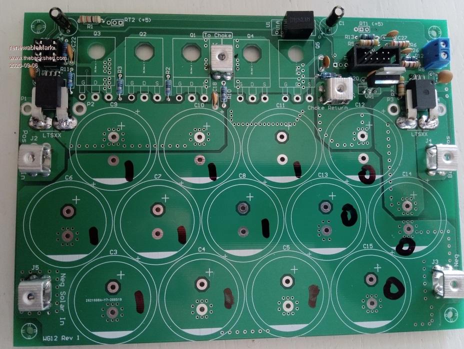 Cheers Caveman Mark Off grid eastern Melb |
||||
| poida Guru Joined: 02/02/2017 Location: AustraliaPosts: 1420 |
Mark: not to worry. This project will work with just about any reasonable collection of caps. No need to be exact. I would fit 4 caps to the output. The first board I built ended up donating all it's caps to the Wiseguy board build. And so I thought, what could I get away with if I took an attitude of "let's be stupid" when fitting caps? So this board has 1 x 540 and 1 x 450uF on the input. And 1 x 10,000 uF on the output. And the firmware still works fine when driving the 1 Ohm load. I suspect it will be also great when driving a proper sized battery. If I can make a suggestion, I would build just one board first. Have a bit of a play with it. Give it 50V input and configure it to charge a single 12V battery. This will give you a feel for setting up a board. Maybe make a big power resistor of about 1 Ohm and hook it up to the output. Starting with a blank Nano, load the firmware, connect to the serial console and load the defaults. (you will need to config the serial console firstly to run at 115200 baud. Then set it to send a "Newline" only when sending data) Assuming you have a brainboard and power board built and connected to each other, hook up the 50V. Then the 12V supply to the power board. Then, set the zeros for the two current sensors. Connect a battery. Now use the multi meter to check and calibrate the input voltage and the output voltage. Use the DC clamp meter to check and calibrate the output current. How to calibrate? have the mppt powered up, note the LCD, it will show "NIGHT" if not producing any output. Who cares, that is good enough to calibrate input voltage. DMM says input is 49.5V for instance.. send "C" to the nano After sending a "C" you will see "Input volts cal. Enter volts" Ok, tell it by typing 49.5 and press "send" a little while later, the LCD will now show 49.5V as input. likewise, we calibrate all the others. (Vin,Vout, Iin, Iout) And then set up all the charge program details. here is the latest code. It has a few small improvements. One is we define the NTC position in the voltage divider. It should be self explanatory. mpptv5_highside_NTC.zip The file has "highside" in it but it is flexible and can deal with either highside or lowside NTC positioning. wronger than a phone book full of wrong phone numbers |
||||
| wiseguy Guru Joined: 21/06/2018 Location: AustraliaPosts: 1156 |
Mark, where did you obtain the screw terminal connectors ? I ordered mine from Ali nearly 3 months ago and still waiting..... I am getting close to having an MPPT test bed finished. I used a normal diode as the flywheel part and a 30V supply it all worked well. Then I inserted a HY4008 as the lower diode which also started out working well, but applying a very low R load to the output immediately killed the HY4008 dead as a dodo. First FET I've killed in ages. I am confident that a diode would not have died & I must admit that with the gate tied solidly to the source, and the Drain Source diode being reverse biased I dont understand the mechanism that killed it. So I will investigate this further with some other disposable FETs and try to figure out why is it so. I have also had a bit of a play with snubbers and will take some screen shots of over, under and critically set up snubbers and how to select values for them. If at first you dont succeed, I suggest you avoid sky diving.... Cheers Mike |
||||
renewableMark Guru Joined: 09/12/2017 Location: AustraliaPosts: 1678 |
Thanks Poida, I have had way too many sav blancs to comprehend what you wrote, I'll look at it tomorrow. I t may make sense then. I'm guessing we communicate to the brainboard like we do the nano? Mike I got them from ali. I have some spare I could stick in an overnight bag, considering how sh*t oz post is currently you may get them in a couple of weeks. yell out if you want them, I think there is enough for one more board, there are more on order. Cheers Caveman Mark Off grid eastern Melb |
||||