|

|
Forum Index : Electronics : 6Kw Ozinverter build
| Author | Message | ||||
Madness Guru Joined: 08/10/2011 Location: AustraliaPosts: 2498 |
That link does not work. That is strange, the 2110's don't normally just fail, was the voltage too high from something wrong with the TIP35 or the Zener? Test all your voltages (5V & 18V) and signals from the EG8010 before putting any drivers back in. There are only 10 types of people in the world: those who understand binary, and those who don't. |
||||
renewableMark Guru Joined: 09/12/2017 Location: AustraliaPosts: 1678 |
Yeah they are ok now, weren't before. Cheers Caveman Mark Off grid eastern Melb |
||||
renewableMark Guru Joined: 09/12/2017 Location: AustraliaPosts: 1678 |
I meant a sope like this Cheers Caveman Mark Off grid eastern Melb |
||||
Madness Guru Joined: 08/10/2011 Location: AustraliaPosts: 2498 |
I bought my crt type CRO through Gumtree for $100 with a frequency meter. The guy selling was trying to make his car run on water but gave up and sold the test equipment. There are only 10 types of people in the world: those who understand binary, and those who don't. |
||||
renewableMark Guru Joined: 09/12/2017 Location: AustraliaPosts: 1678 |
Gee, I wonder why he gave up on that idea? Yeah I tested the 8010 and it was putting out the square waves, I don't know how, as the other voltages were not right. I tried testing the PWM but didn't get any readings, I put it down to my crappy scope, but it was in fact that at first turn on they would have fried from over voltage. It's tested to the best of my ability now. But the resistance on the fets between the right two pins is only 3.5 mega ohm when the ribbon cable is hooked upto the control board. I seem to recall it was around 7 mega ohm is the same scenario previously. With the ribbon cable not connected the reading is 7+ mega ohm on the fets. Probably wise to replace all the parts on the control board I haven't done yet since the big failure. Haha I'll probably get it singing nicely the day your boards arrive. Cheers Caveman Mark Off grid eastern Melb |
||||
Madness Guru Joined: 08/10/2011 Location: AustraliaPosts: 2498 |
If you are testing the control board on its own without the IR2110s fitted you can make sure the all the voltages are right and the correct signals are coming from the EG8010. Then fit the IR2110's and there should be nothing to blow the IR2110's, test the output of the IR2110's, if that is good it should work. The resistance you are getting on your power board sounds right to me. There are only 10 types of people in the world: those who understand binary, and those who don't. |
||||
| poida Guru Joined: 02/02/2017 Location: AustraliaPosts: 1420 |
Mark, I have 4 oscilloscopes. 2 DSOs, 2 analog CROs. I live in the outer Eastern suburbs of Melbourne. If you want you can borrow one, plus probes for a little while. The DSOs are: Rigol DS2072 2 channel, 2 Gsample/sec, hacked to 200Mhz bandwidth Rigol DS1054Z 4 channel, 1 Gsample/sec, hacked to 100Mhz bandwidth Analog CROS are: Tektronix 2235 2 channel, 100Mhz Tektronix 465M 2 channel, 100Mhz DSO scopes are way, way more useful. You can record 20 seconds of stuff at very high time resolution, stop and review it in fine detail. wronger than a phone book full of wrong phone numbers |
||||
renewableMark Guru Joined: 09/12/2017 Location: AustraliaPosts: 1678 |
Thanks Poida, that's very kind of you. I don't normally like borrowing electrical stuff like this though. Probably all I need is a quick visit to see if the control board is doing it's thing properly. That would be fantastic if I could clarify that. Cheers Caveman Mark Off grid eastern Melb |
||||
| poida Guru Joined: 02/02/2017 Location: AustraliaPosts: 1420 |
Let's sort out details of a visit via PM? wronger than a phone book full of wrong phone numbers |
||||
renewableMark Guru Joined: 09/12/2017 Location: AustraliaPosts: 1678 |
Thanks mate, I'de be stuffed without all the help from all the guys here. Cheers Caveman Mark Off grid eastern Melb |
||||
Madness Guru Joined: 08/10/2011 Location: AustraliaPosts: 2498 |
Very generous of you Poida, Mark not saying you should not take up Poida's offer but I would keep an eye out for secondhand CRO anyway. There are only 10 types of people in the world: those who understand binary, and those who don't. |
||||
renewableMark Guru Joined: 09/12/2017 Location: AustraliaPosts: 1678 |
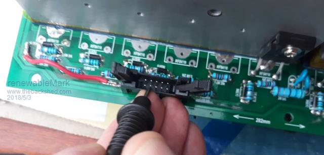
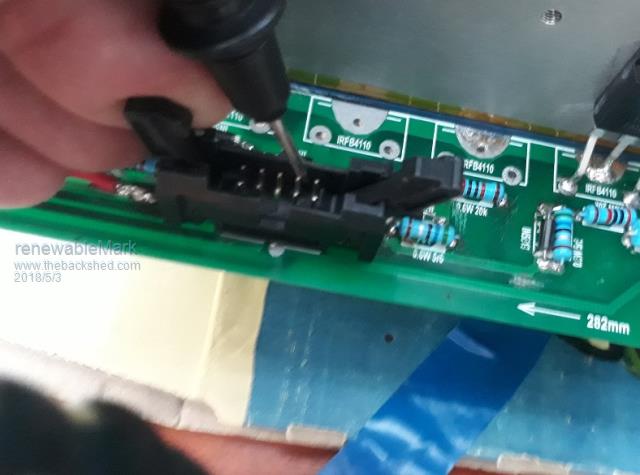
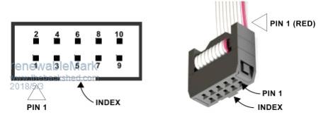
I think I have found a problem. What I did is power the power board only by feeding the dc neg cables and pos heatsink with 50v. Pins 3 and 8 both show 50v, from what I can see those pins go direct to the 2110 chips, correct? Is that normal?    Cheers Caveman Mark Off grid eastern Melb |
||||
| Tinker Guru Joined: 07/11/2007 Location: AustraliaPosts: 1904 |
Mark, it is too bad nobody ever bothered to draw a schematic of those ozinverter board(s). With that people who do not have these boards (like myself) could give you better clues where to check. The first thing I did before laying out my PCB is drawing the schematic  - its not rocket science and there are free programs to do it on the net. - its not rocket science and there are free programs to do it on the net.Now, assuming you *only* connected the battery to the power board you should see 50V at two of the mosfet drains and ground at the source of the two others. I can't imagine why you measure that at the 10pin skt when nothing is plugged in there. From what I wrote above, check how that 50V could get to the 10 pin skt by tracing back the PCB tracks. Klaus |
||||
Revlac Guru Joined: 31/12/2016 Location: AustraliaPosts: 1026 |
Gate to Source resistor.  Cheers Aaron Off The Grid |
||||
renewableMark Guru Joined: 09/12/2017 Location: AustraliaPosts: 1678 |
I kept blowing 2110's and looked at where that could be coming from. Cheers Caveman Mark Off grid eastern Melb |
||||
renewableMark Guru Joined: 09/12/2017 Location: AustraliaPosts: 1678 |
Measuring in circuit all resistors look fine, do you need to desolder one end to check? Cheers Caveman Mark Off grid eastern Melb |
||||
| Tinker Guru Joined: 07/11/2007 Location: AustraliaPosts: 1904 |
Mark, I would suspect *all* the parts around the mosfets that blew. Yes, you need to unsolder one leg to test the resistors/diode. Klaus |
||||
renewableMark Guru Joined: 09/12/2017 Location: AustraliaPosts: 1678 |
Thanks Klaus, reckon I'll just rebuild the power board again, I have plenty of spares. Cheers Caveman Mark Off grid eastern Melb |
||||
Revlac Guru Joined: 31/12/2016 Location: AustraliaPosts: 1026 |
No, the Gate to Source resistor bleeds voltage through from pos rail to those pins 3 & 8 through the gate resistor. Just powered op my board with resistors in and no fets plugged in yet, same thing. Normal.  Hope I wasn't looking at that upside down.  Cheers Aaron Off The Grid |
||||
renewableMark Guru Joined: 09/12/2017 Location: AustraliaPosts: 1678 |
Thankfully Poida has offered to look at my issue. I'de really like to sort it out myself, it really frustrates me being beaten by something, however this isn't my forte. Should have good news by the weekend. Thanks for taking the time to look at it and the replies. Cheers Cheers Caveman Mark Off grid eastern Melb |
||||