|

|
Forum Index : Windmills : Diodes on star centre connection
| Author | Message | ||||
| Warpspeed Guru Joined: 09/08/2007 Location: AustraliaPosts: 4406 |
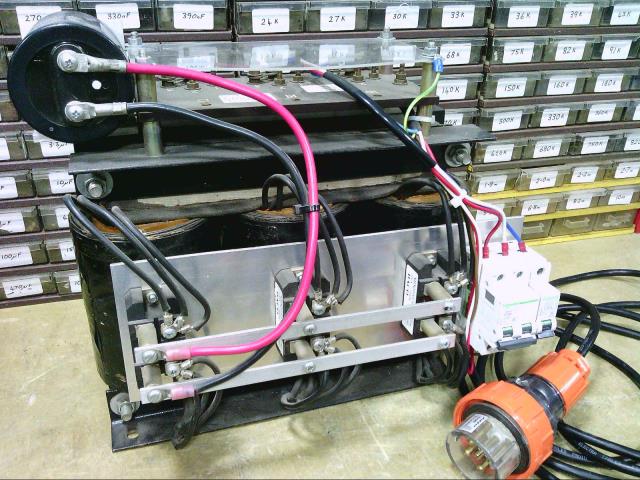
Where do you get this great idea on paper stuff ? You are not the only person that actually builds and tests things. This works exactly as I said it does, I even tested it with a 6KVA three phase transformer and a rectifier in both configurations. Just to show you, I just now took a picture of the original test setup, exactly as it was back then. Its still connected up in parallel configuration. Somewhere here I have the diagonal shorting bars to connect it up in series.  Never tried it with a small alternator though, but if there are differences I would expect its because our sine waves may have significant distortion. I don't know what your alternator waveforms are like under load, but the mains waveform here is truly horrible. That could skew the results significantly for both of us. Cheers, Tony. |
||||
| DaveP68 Senior Member Joined: 25/11/2014 Location: New ZealandPosts: 292 |
Tony you were the one who proposed this idea not me. All I did today was publish some 'actual' results out of an F&P stator which is what you seemed to be after at the time. Didn't mean to cause any upset today. You were all ok with the test results last year. Here's your reply. But at very low wind speeds we cannot load the alternator to anything like its full current capacity anyway, without stalling the blades. The driving torque to do it is just not there, so its not a practical limitation. Its about the best we can do for max dc voltage at low rpm with just an alternator and some diodes. The previously suggested mosfet switching scheme should work to give a hazard free changeover, but I have not actually tested this myself. Isolated gate drive power could be provided (initially for testing) from a couple of 9v batteries. PS edit Don't see any form of PMA in your photo, let alone a Fisher & Paykel stator which this topic was mostly about. So Tony I just don't get where your coming from... There are realities if you do not accept, will lead to frustration because you will be spending time on wrong assumptions and the results cannot follow! The Dunning Kruger Effect :) |
||||
| DaveP68 Senior Member Joined: 25/11/2014 Location: New ZealandPosts: 292 |
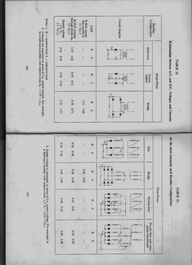
 On a separate note on things you seem to like pulling me up on the "R" in page that you posted on another topic (also above) stands for "Resistive Load". This is why the figure is you state is 0.82 and not the 0.72 to 0.73 I measured. That's close enough to the 1.4 times I stated before or in other words the AC current was 73 % of the rectifier DC output value for that test. As saturation is approached the reading changed to about 72 % on one test I did. The load I use for measurement isn't resistive, so my figures are actual and correct. My load uses a PWM system with a low value resistor which changes the conduction angle in the rectifier depending on what current is taken. A resistive load is different due to the diodes in the rectifier conducting over a much wider range of the waveform. There are realities if you do not accept, will lead to frustration because you will be spending time on wrong assumptions and the results cannot follow! The Dunning Kruger Effect :) |
||||
| DaveP68 Senior Member Joined: 25/11/2014 Location: New ZealandPosts: 292 |
Oh one more thing Tony you have crossed a line just like Phil (fillm) has many times with me stating this sort of thing... Barky seems to have the whole plan worked out in very great detail. Lets just be patient and watch the whole magnificent thing take shape. Don't think I'll bother with making any more contributions with the way I've been treated on here and that's a shame as I have lots more to offer. Bye Bye There are realities if you do not accept, will lead to frustration because you will be spending time on wrong assumptions and the results cannot follow! The Dunning Kruger Effect :) |
||||
| Gizmo Admin Group Joined: 05/06/2004 Location: AustraliaPosts: 5078 |
Settle down guys, please keep it civil. Glenn The best time to plant a tree was twenty years ago, the second best time is right now. JAQ |
||||
| get real Newbie Joined: 16/12/2020 Location: United StatesPosts: 9 |
Barky seems to have the whole plan worked out in very great detail. Lets just be patient and watch the whole magnificent thing take shape. Don't think I'll bother with making any more contributions with the way I've been treated on here and that's a shame as I have lots more to offer. Bye Bye Is Dave gone for good? Where ole where is Dave. He put out some good info on here. |
||||
| get real Newbie Joined: 16/12/2020 Location: United StatesPosts: 9 |
About 10 years ago I was talking with a auto electrician mate who said he was starting to see car alternators with the diodes on the star. He said on the test bench they were definitely making more power. I've been trying to find some more info on google, but its knowing the right question to ask thats the hard bit. On one thread I did read a 10% gain, at a fixed rpm into a battery load. Of course this also means more power is needed to drive the alternator at the testing rpm. I suspect the power output for a fixed rpm would be somewhere between star and delta. Gizmo Is there a pic on here showing how to hook up an F&P Motor to a battery? or can you tell me?  |
||||