
|

|
Forum Index : Electronics : 8 KW Inverter Build
| Author | Message | ||||
Madness Guru Joined: 08/10/2011 Location: AustraliaPosts: 2498 |
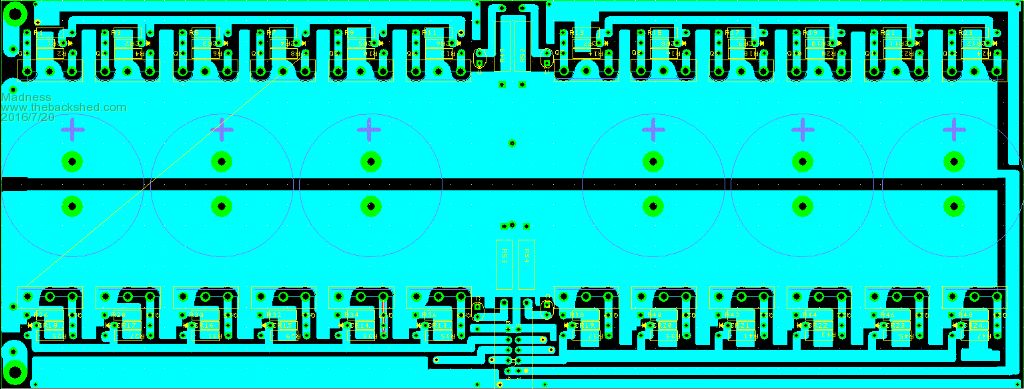
Hi Oz, I am redoing my board with IRFP4110PbF Mosfets, had to rotate them 180 degrees to the other design. This is to allow them to screw onto the 50 X 25 X 300 Aluminium bar that I will bolt to the heat sink on the bottom side of the board. For conductors I am going to flatten copper pipe and solder them flat onto to the bottom power rails and for the bridge fold the flattened copper to 90 degrees leaving about a 10 mm wide section to solder to the copper in all 4 positions on the bridge's. These will then have a couple flexible cables bolted to each of the copper bars. Is a 20 amp breaker not quick enough to save the mosfets in your testing? Each circuit in my setup has that protection, don't get many shorts, if I need to have spare pcb on hand if that happens then so be it. I plan to build a 3 KW version as and emergency backup anyway. 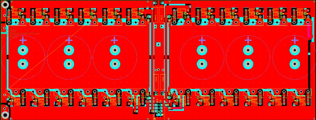
There are only 10 types of people in the world: those who understand binary, and those who don't. |
||||
| Tinker Guru Joined: 07/11/2007 Location: AustraliaPosts: 1904 |
That's an interesting alternative to what I described in "building an inverter from scratch". We shall see which idea works better    . .
You will need a mighty big soldering iron to solder that flattened pipe to the PCB. I suggest you pre tin the copper first. Where I can see a possible problem is in flattening the pipe perfectly straight. These conductors were sooo much easier done from copper strips guillotined of 1.6mm copper sheet. Or a 3 x 20 mm copper strip, like a mini bus bar. I had a strip like that but can't remember where I got it from to get some more. Might be worth while to check the shops that sell brass strips, they might have them in copper too. Even flat enameled wire like somebody else used for the choke winding. The enamel would need to be first burned off though. But if pipe is all you can get... Anyway, have fun, I'm following your build with interest. Klaus |
||||
oztules Guru Joined: 26/07/2007 Location: AustraliaPosts: 1686 |
It is not a problem in normal house operation, the fact that it drives the house loads without any problem in any way masked this problem, and it wasn,t unitl I tried to test this aspect that I came undone, in normal operation of a house with any loads it is likely to encounter, it is a non-event, and I have plenty of spare inverters, but never need any of them. No this is protection against a highly unlikely event.. even a long extension lead would probably mask the problem, but it is there. 7kw no problem, 8 and 9 no problem., today 10kw no problem, but a short with a torroid is way in excess of that apparently, and I have no answer for it as yet.... a big choke would probably push this back so far that it would be immaterial I suspect... but thats not the point.... it is a technical failure.... and it's annoying me for the ones going out to the outer islands... simple and cheap to provide secondary back ups... which we do anyway, but thats not the point ....... For me it is not a problem at all, I can fix it in 30 mins... and they have never failed in real life operation.... but for other people???..... so I will keep at it until I find out why I'm failing at this. To be honest, thinking about it, I have never tested a PJ in a dead short wired to it solidly... spark type shorts seem ok... but a solid wired short... no... not tested... thus far. I probably wont do it to the PJ as I cant always fix them if the totems send power back further.... blew up enough doing the inverter charging faults 
As Glen has found, in normal running they are perfect..... and thinking about it, the fact it blows them up in the charging disconnect mode, may mean a hard wired short would probably do them in too  ... never really thought about it....no .. it does not have a current sense on the input line, so thats not relevant ... never really thought about it....no .. it does not have a current sense on the input line, so thats not relevant
Tinker... do you have anything to report now your back in the saddle? ..........oztules Village idiot...or... just another hack out of his depth |
||||
Madness Guru Joined: 08/10/2011 Location: AustraliaPosts: 2498 |
Hi Oz & Tinker, Will see how I go with the copper, 3 X 15 X 250 mm is available on Ebay for $6.79 posted. I was inspired by your design Tinker, how did that work out for you? http://www.ebay.com.au/itm/99-6-T2-Purple-Copper-Cu-Flat-Bar-Plate-3mm-x-15mm-x-250mm-Metal-Strip-/322136474217?hash=ite m4b00d48269:g:xksAAOSwzJ5XUn7l Oz the Trace Inverter manual talks about accidentally connecting AC out of phase by 180 degrees which they describe as being far worse than a short, could it be when those Chinese inverters switch to charge they could be hitting that situation? Perhaps a dead short will not be so catastrophic. Would a fuse protect the inverter like this? http://www.cesco.com/b2c/product/Bussmann-JJN-100-T-Tron-Class-T-Very-Fast-Acting/54775 There are only 10 types of people in the world: those who understand binary, and those who don't. |
||||
| Tinker Guru Joined: 07/11/2007 Location: AustraliaPosts: 1904 |
Oztules, I redid the mains board to accept the 230/12V isolation transformer. Have not yet found time to test it but am confident it works. Next step is unwinding two of my 3 identical ( they were even manufactured on the same day)3KW Aerosharp toroids to get the cores ready for a dual stack. As you will appreciate that task can take some time so when I have some pictures of that process and my ideas of winding them actually work I certainly will post them here. Madness, the design I posted worked in the testing stage with a smaller toroid, the dual stack aerosharp core toroid is still in progress. You may be interested what I spotted in perusing the yellow pages when I read that you sourced copper bar on ebay. There is an Australian company that sells the bar in 4 m lengths (they cut it to size they say) which might suit better than the ebay stuff. Many sizes here I know this is not 99% pure copper as used in busbars but should conduct just as well if slightly over sized. What is required is a flat, straight bar that conducts well and solders easily. Tinker Klaus |
||||
fillm Guru Joined: 10/02/2007 Location: AustraliaPosts: 730 |
Hi Mdns, I have bought copper buss bar from this supplier in Brisbane http://www.georgeweston.com.au/ for link bars on lithiums. When it comes down to it, its much easier than flattening copper pipe, and if you need good contact the surface finish then its high quality. It would be a bit of a haul from your place. They do sell small quantities as well. PhillM ...Oz Wind Engineering..Wind Turbine Kits 500W - 5000W ~ F&P Dual Kits ~ GOE222Blades- Voltage Control Parts ------- Tower kits |
||||
Madness Guru Joined: 08/10/2011 Location: AustraliaPosts: 2498 |
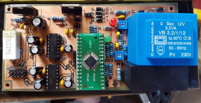
Been busy with work but have made some progress, I have redesigned the control board. My plan is to get a few made professionally, so I have made it double sided and reduced the size so it will keep costs down. The only change I have made to the circuit is to add pins to connect an LCD display, I figured this may be helpful at the testing stage if nothing else. Finally found a reliable method to do toner transfer for etching. 1 Print top and bottom onto glossy paper with Laser Printer 2 Staple the 2 sheets together with toner on the inside and perfectly aligned 3 Clean PCB with fine sand paper 4 Cut the leading edge of the paper so that just the edge of the PCB is exposed when PCB is in the correct position 5 Run this through a laminator at maximum temperature and minimum speed a few times, leave the laminator running 6 Then put the pcb with paper still on in the oven preheated at 165 degrees for 5 minutes 7 Put straight back through the laminator several more times while hot 8 Soak in water with a bit of detergent for 10 minutes 9 Rub off the paper with your fingers, if done properly the toner will have stuck very well and won't rub off 10 Dry it out and etch, I use 2 parts 3% peroxide to 1 part hydrochloric acid 11 Once etched clean off the toner with Acetone 12 If you want a silk screen repeat with a sheet on the top with silk screen printed on it The oven stage could be eliminated if you can get the lmintator to a higher temperature As yet I have not put power on either board, trying to find a supply of spare smoke before jumping in the deep end. My Mosfet board is almost completed also, just adding wires for power in and out for testing, once again it is only a prototype and will get some of them manufactured also. 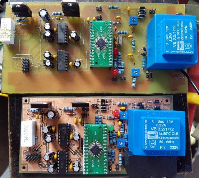
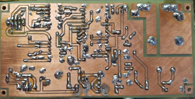
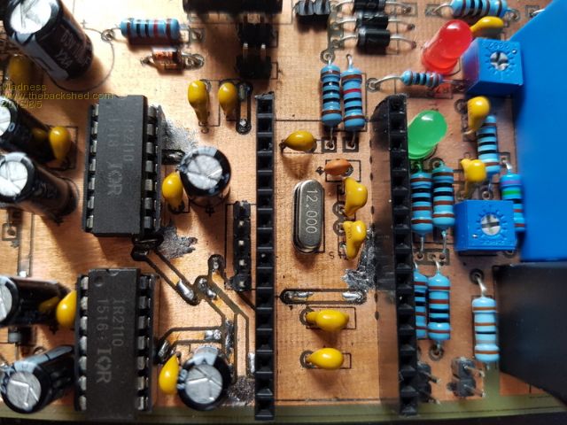
There are only 10 types of people in the world: those who understand binary, and those who don't. |
||||
| Tinker Guru Joined: 07/11/2007 Location: AustraliaPosts: 1904 |
Hi Madness, did you do a search on PCB making on this forum before spending lots of time coming up with the above? Starting about 5 years ago some of us went through this exercise and came up with a method that is still used by myself. And it appears to be easier and simpler too. Do a search for the word "ultrakeet" and read all the posts there if you have time. Also read the last post on the first page at the new PCB forum here. Then you might want to read this: link to laminater modifications. I'll add a few points to your list above which might interest you: 1a. I use cheap toner transfer paper which I got on ebay from china. Its A4 size and works heaps better than that blue paper the local electronic shops (Altronics, Jaycar) sell. 3a. I clean mine with stainless steel wool under running water, then dry them (paper towels) without touching the copper surface, then spray them with PCB cleaner, then dry them again. Repeat, do NOT touch the copper surface, the oil on your finger skin will spoil the cleanliness. After this I immediately do the toner transfer thing. 5a. Any standard laminator set to its max temp is *not* hot enough. Try to find the cheap Lowell home laminator and modify it as per the article in the link. This then works perfectly after only two passes and no oven pre or post heating. The oven takes the 'fun' out of this job IMO  , unless you are allowed to do the job in your kitchen , unless you are allowed to do the job in your kitchen  . .
8a. no need for detergent if you use that ebay toner transfer paper. 9a. Please do NOT rub the toner with your fingers nor touch it at any time. Let the PCB soak a little in water and the paper will lift at the edges. Gently grab it there with tweezers and *peel* it off, slowy, watching the pattern on the board as the paper peels back. 9b. Dry the board between paper towels by gentle pressure - no rubbing. 9c. This step is *important*. Get a pack of green TRF (toner resist film)from that ultrakeet mob. Follow the instructions, especially with respect of keeping the TRF film tight as it passes through the laminator. This will add an *extra* film to your pattern, making it look green. You can now see very well where there might be a slight coverage problem and correct it with a PCB pen - I do that under an illuminated magnifying glass. You will have banished toner porosity forever with this addition. 10a. I etch mine with ferric chloride in an etch tank (has bubbler and heater), whatever works for you. 11. No need at all to mess around with acetone, just grab that stainless scrubbing pad again and rub the toner & TRF off under running water. If you are planning to do a few PCB's its well worth while to look into how others did it. I used to lay out PCB's professionally back in the time before computers made it so much easier. Nowadays I can make my boards at home easily but I only do single sided boards. While your stapling method may work well enough I dare say its not accurate enough for a bigger board. Remember, paper is not dimensional stable. Klaus |
||||
Madness Guru Joined: 08/10/2011 Location: AustraliaPosts: 2498 |
Hi Klause, Thank you for your input. I did a lot of research but did not see your information come up when I was using Google. The laminator I have now came from the shop at the local rubbish tip, cost me $5 and is a commercial grade pouch laminator that will take up to 320 mm wide. One day I might get around to modifying it for the higher temps but I have no problem getting access to the oven. On my to-do list is to get a toaster oven and modify it with an Arduino for doing SMD boards. It will be easy to add a temperature setting for doing stuff like heating the PCB to set temperature. I have that Chinese paper stuff, my Kyocera printer/copier will not feed it. I tried everything I know, I was a copier tech in a previous life. Solved many problems that others could not, including the Japs in the factory but I can't get that paper to feed in the machine I have. However I got fairly good results with transparency film, but not perfect. Have to agree with you on the blue stuff, it is a big waste of money. The method I used works perfectly, including double sided PCB's, yes paper shrinks when it goes through the fuser but both top and bottom sheet shrink at the same rate. However, this is reduced to almost nothing if you use very dry paper, one way to achieve that is to microwave it(if you can't get to the kitchen then I have no solution), fresh out of the packet is not dry. On my Mosfet board design which is 100 X 250 mm alignment is perfect. With the method I used and as I mentioned, it sticks hard to the copper and will not move. It will not rub off with my fingers, even a scrubbing brush won't touch it. Getting off with a stainless steel pot scrubber would be hard work. One final step I forgot to mention is I heat the board with a heat gun till it is quite hot but not enough to discolour before etching. After this step, it is not porous. Peroxide and Hydrochloric acid works very well for etching and it regenerates itself with oxygen from the air. Different toners behave differently, the method I described is working very well for me. The Kyocera does print a very solid black, much more so than others like the HP I used to have. This method works 100 % every time, there is no touching up, it is cheap. Took me a lot of time to perfect it, if I had of known of another method I would have tried it. No one mentioned to me your method when I spoke about experimenting with toner transfer previously on this forum. Only think I found on here was a method to cut out bits and stick them together to make the art work, I have a computer and printer that can do that with PCB design software. If only I could easily plate through the holes! There are only 10 types of people in the world: those who understand binary, and those who don't. |
||||
| Tinker Guru Joined: 07/11/2007 Location: AustraliaPosts: 1904 |
Hi Madness, I use a cheap (it cost $69.-) Samsung laser printer. It just a printer, no copying. I had to set it to 'card stock' to get the toner to stick well to that Chinese paper. I'm still on the toner cartridge it came with, a new cartridge would cost more than the printer did. So, when it runs out its a new cheap printer for me. I suppose the toner is different in your printer to get that hard black finish. I have been told the toner in Brother brand printers is no good for PCB transfer. In the long run you will most likely modify that laminator (but it then cannot be used for anything else) to do the PCB boards. The most important thing is the rollers inside must be spring mounted, a 1/16" PCB is a lot thicker than a standard laminating pouch. The reason I do not like the oven pre heating is that one then has to attach the copied pattern to a hot board if I understand your method correctly. Its bad enough to grab the hot PCB as it emerges from the laminator to feed it through again. Interestingly, I do have an old bench top oven in my shed I use to heat up things (smelly) inside if required. So, you are planning to flow solder SMD components in an oven? I'm curious about that, I always thought they use hot air to flow the solder paste quickly rather than cooking the whole board and possibly the components on it. But I may be wrong, technology changes so fast these days. Klaus |
||||
Madness Guru Joined: 08/10/2011 Location: AustraliaPosts: 2498 |
Yes, fiddling with hot PCB is not fun, I laminate it several times before going in the oven. Then the paper is attached quite securely, the oven is preheated, not the PCB. After 5 minutes in the oven, it goes straight back in the laminator. The Laminator I have has variable temperature setting already, probably just need to add a variable resistor in series with the thermistor. Here is a link to what appears to be a very high standard reflow oven build. http://whizoo.com/reflowoven There are only 10 types of people in the world: those who understand binary, and those who don't. |
||||
fillm Guru Joined: 10/02/2007 Location: AustraliaPosts: 730 |
Hi Mad, Looking good, mine has come to a halt for a bit but on the subject of PCBs. I have done mine in the CNC but its a pain to get from express .pcb or gerber into DXF. Below is a pic of a Wind Control board I was doing a couple of years back but have a far better solution now. 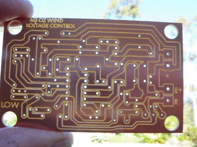
Also it is easy to make your links active so it becomes a click on 1-Copy the url ( as you already do ) 2-click on the chain link on the globe box 4 in on the Post tool bar 3- Copy ihe link "cntrl V" into the box ( or type "Link Here" or whatever you want) 4- Click OK 5-Copy the same again 6-OK Now your link will be active on the post http://whizoo.com/reflowoven like this LINK HERE or like this  PhillM ...Oz Wind Engineering..Wind Turbine Kits 500W - 5000W ~ F&P Dual Kits ~ GOE222Blades- Voltage Control Parts ------- Tower kits |
||||
Madness Guru Joined: 08/10/2011 Location: AustraliaPosts: 2498 |
Hi Phill, So CNC is not so good or just the software is the issue? I have been investigating 5 Axis CNC mills for a friend for making jewellery. Many years ago I operated a CNC machining centre in the late 1970's, used to run on punched tapes back then. Gary There are only 10 types of people in the world: those who understand binary, and those who don't. |
||||
fillm Guru Joined: 10/02/2007 Location: AustraliaPosts: 730 |
Md, The CNC is fast and exact as you would of course know but I dont think punched tapes is CNC ( Computer Numerical Control ) . Then a workshop full of highly qualified machinists is now replaced by one person looking through a window of an enclosed cutting booth. A good friend has a very large hydraulics workshop full of CNC machines. The last one he bought was well over $300K and it does not bat an eye lid at 10mm cuts.Its mind blowing what is out there these days Anyway the main problem is the material left , as you can see the fine copper lines between cuts and it can take a lot off the neighboring track and also leave a copper fiberglass powder in the track. It has to be cleaned and checked. This was just one method I was playing with and in Cambam it will cut with a PCB isolate style but what I can gather from the Gurus is that you just draw the circuit with in CB. I have not explored it all to far but it would be better to be able to convert gerbers ect ... But having time to try and get it sorted ..one day. PhillM ...Oz Wind Engineering..Wind Turbine Kits 500W - 5000W ~ F&P Dual Kits ~ GOE222Blades- Voltage Control Parts ------- Tower kits |
||||
| Tinker Guru Joined: 07/11/2007 Location: AustraliaPosts: 1904 |
Thanks for that link madness, that looks like a very interesting project. Their oven looks very much like the one I scrounged from the kerb but mine had two hotplates on top which I removed. As these ovens are so cheap I would start with a new one as in the article. Anyway, where would you get your solder paste from? I would like to try it but have not seen solder paste for sale in my electronics shop (Altronics). Regarding the CNC method of PCB making, it a novelty IMO. If it were that good then one would see commercial boards made that way. I have yet to see one, they all appear to be etched. Now, if one had a three dimensional NC table that could print in copper, *that* would be useful. Imagine, tracks as thick as one liked and where on the board one liked. Klaus |
||||
Madness Guru Joined: 08/10/2011 Location: AustraliaPosts: 2498 |
Hi Phil, CNC, Computer numerical control, tapes were made by a programmer and run through and rewound to start the next cycle, it had Nixie tube numerical readouts for each axis. It was at the Toowoomba Foundry, biggest jobs I did on it where big direct drive windmill crankcases, about 1M X 1.5 (very much larger than your standard farm windmill) but would take much larger castings than that and had a 24 tool turret. This was late 70's, machine was made by Cincnatti, I believe Sir Jack Brabham used one the same machines for building engines. Hi Klaus, I have bought solder paste on Ali Express, also can be bought from RS Components and others. CNC PCB making is probably more suited to prototyping and small runs. There are people using 3D printers to apply artwork to PCB prior to etching also. Printing conductive tracks is possible, they are printing Jet Engine Turbine Blades with 3D printers now. Gary There are only 10 types of people in the world: those who understand binary, and those who don't. |
||||
fillm Guru Joined: 10/02/2007 Location: AustraliaPosts: 730 |
Hi Mds, You are a man of many facets. I think the first types of automated machines were just NC , all I can say is one day "they" will wake up to the fact that skills and manufacturing is vitally important to an economy to keep with in our shores at whatever cost, once lost it is very hard to regain lost ground. Tinker, I agree there are probably many ways of mass producing boards but drill will still be CNC and is probably why its easier to get a drilling DXF for a PCB.How the main stream manufacturing places do it I don't know but for prototyping and low production back yard stuff its great as it makes designing enclosures and putting perfect holes and fitting a breeze. As for having to build ovens and all the other paraphilia in my eyes a cnc has far more uses. If cambam could have a components library would be handy but as always where there is a will they is always a way. PhillM ...Oz Wind Engineering..Wind Turbine Kits 500W - 5000W ~ F&P Dual Kits ~ GOE222Blades- Voltage Control Parts ------- Tower kits |
||||
Madness Guru Joined: 08/10/2011 Location: AustraliaPosts: 2498 |
Hi Phill, Manufacturing in Australia is certainly in huge decline, I think what we can offer to the world is innovation. There are so many smart Ozzie's who's ideas have been swept aside or taken overseas and our country has had little or no benefit from it. One idea I have had is to crowd fund a High Tech Incubator to provide support and help source funding for Ozzie's. Just heard about a similar idea in India that is getting a lot of good results, surely we can compete. As I heard someone say recently "Australia is a great country in spite of our politicians". There are only 10 types of people in the world: those who understand binary, and those who don't. |
||||
fillm Guru Joined: 10/02/2007 Location: AustraliaPosts: 730 |
Hi Mds, Agree, but politics is way off topic and political debates just ramble on and on and go nowhere and its not what TBS is about. I am sure visitors and members would rather read about you inverter build.. PhillM ...Oz Wind Engineering..Wind Turbine Kits 500W - 5000W ~ F&P Dual Kits ~ GOE222Blades- Voltage Control Parts ------- Tower kits |
||||
Madness Guru Joined: 08/10/2011 Location: AustraliaPosts: 2498 |
A little more progress, I have now attached the power PCB to the heatsink. This was done with a 50 X 25 X 300 mm piece of aluminium, it is screwed to the actual heatsink with 12 6 mm Allen screws with thermal paste in between to get a good thermal transfer. Drilling and tapping 24 M3 threads for the Mosfets was a slow job as the drill bits wanted to clog, so had keep cleaning the drill about every 1 mm of hole depth. 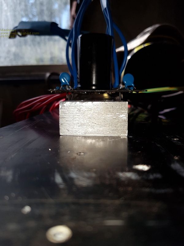
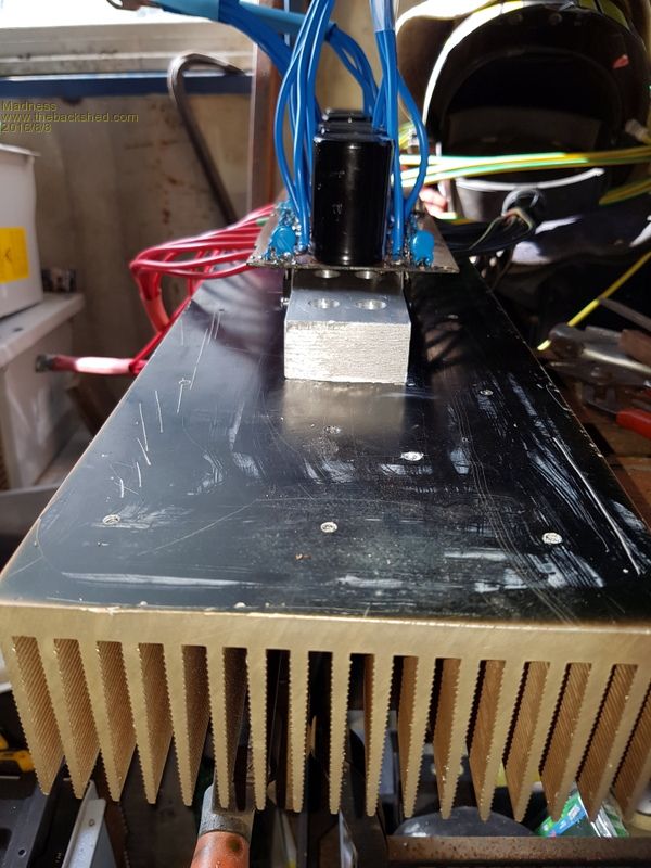
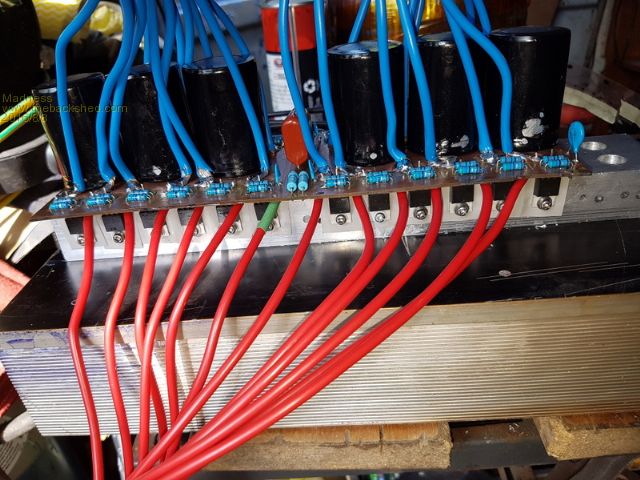
This PCB will be replaced with a new one with copper bars instead of all the individual wires, also with IRFP4110PBF MOSFETs. The PCB has the pin spacings to suit the heavier duty MOSFETs so they will have a minimal lead length to the PCB. This build of the PCB is more of a prototype to check the design before getting some manufactured. There are only 10 types of people in the world: those who understand binary, and those who don't. |
||||