
|

|
Forum Index : Electronics : building an Inverter from scratch
| Author | Message | ||||
Grogster Admin Group Joined: 31/12/2012 Location: New ZealandPosts: 9307 |
These MOSFETS here are the ones I am looking at. I expect it was a similar listing, Tinker? Also, if you are reading this, Tinker, please can you list the specs of the current transformer you are using? It is shown as C/T on your schematic, but there is no part number or specs as to what it actually is. You also do not mention the specs for the diodes used for the bridge being fed from the C/T. Are these just standard 1A silicon diodes like 4007's? Smoke makes things work. When the smoke gets out, it stops! |
||||
| Tinker Guru Joined: 07/11/2007 Location: AustraliaPosts: 1904 |
The mosfets came from ali express. I tried to list the url but it does not work here. I can look it up by going back to my original order but for some reason cannot post a valid url - sorry. They were a little cheaper too (5% discount), perhaps you can look it up. C/T came from a junked 1200W PVE Latronics inverter, it was too good to throw away. Specs were 0.1V/Amp, it has a c/t winding and a 9mm hole. "diodes" are small bridge rectifiers, recycled ones from my junk box (you can see them on the photo next to the C/T. Any small bridge will do, they usually have a 400V rating anyway. Klaus |
||||
oztules Guru Joined: 26/07/2007 Location: AustraliaPosts: 1686 |
http://www.aliexpress.com/item/Original-free-shipping-IRFB4410ZPBF-IRFB4410Z-TO220-50PCS-in-Stock/32306911856.html?spm=2 114.01010208.3.134.cUxkkF&ws_ab_test=searchweb201556_9,searchweb201602_5_10017_10034_10021_507_10022_10020_10018_10019,s earchweb201603_2&btsid=a0bcaf17-273b-48dc-b51d-b13757b0433b I'm guessing this one Tinker? ...........oztules Village idiot...or... just another hack out of his depth |
||||
Grogster Admin Group Joined: 31/12/2012 Location: New ZealandPosts: 9307 |
Oztules Tinker link, for those just wanting to click..... @ Tinker: Re: C/T - Great, thanks. Re: Diodes - I thought they probably were, but better safe then sorry.  Smoke makes things work. When the smoke gets out, it stops! |
||||
| KarlJ Guru Joined: 19/05/2008 Location: AustraliaPosts: 1178 |
This little beauty turned up today: Klaus - i have used several of these in the past - in particular on the Ebike stepping down upto 58.8V down to 5V to run LED 3000LM lights which pull >1.5A each 2 of them is no problem but they do warm up cheers Karl Luck favours the well prepared |
||||
| KarlJ Guru Joined: 19/05/2008 Location: AustraliaPosts: 1178 |
re PVE1200 glad you got some good bits after i accidentally hit it with 300VDC array.... got a PVE2500 and a PVE1200 in the shop ATM as well as another Aerosharp 3kW of course you're welcome to them at $0 however..... sooner or later! i'll need help with mine! As it happens i'm now BETA testing my Lithium pack with on-grid inverters - suits peak shaving nicely. Lucky me - I'm putting in a new Victron Easysolar3kW 48V unit. on ebay for ~$3300 + GST considering you get 2x 35A MPPT chargers and an inverter which supports gennie inputs. will be sitting on a 100AH LIFEPO4 48V battery with a 4kW array = HEAPS more available grunt than the 1080AH 24V lead (stuffed) which was fed by a miserable 1kW array and a now broken turbine (due no maint) anyone interested in a 30m tower? with turbine that needs some maint? sing out and i'm guessing a few cartons of beer you would take it away! (edit i think its a whisper 200) Luck favours the well prepared |
||||
oztules Guru Joined: 26/07/2007 Location: AustraliaPosts: 1686 |
The CT I use now is about $2.60 here: http://www.ebay.com.au/itm/281440234858?_trksid=p2057872.m2749.l2649&ssPageName=STRK%3AMEBIDX%3AIT Diodes I used were in4007.... about 1cent/piece http://www.ebay.com.au/itm/Good-Quality-100pcs-set-1A-1000V-Diode-1N4007-IN4007-DO-41-Rectifie-Diodes-/391194554536?hash =item5b150330a8:g:4vIAAOSw3ydVm5H6 or 4 cents/bridge... usually get them for $10/thousand. http://www.ebay.com.au/itm/1A-1000V-DIODE-IN4007-1000PCS-1N4007-DO-41-DEVELOPE-DIY-NEW-IC-I8-/291616363548?hash=item43e5 b0941c:g:n-EAAOSwKfVXEexY ...........oztules Village idiot...or... just another hack out of his depth |
||||
Grogster Admin Group Joined: 31/12/2012 Location: New ZealandPosts: 9307 |
Lovely, thanks. 
I have not actually bought anything yet. I am still doing research. I do like the idea posted by a member here(Tinker?) that if you build the unit yourself, you don't have to worry about using mainboards from China which might not be around when your one fails. The beauty of building your own, is you can design it with modules and parts you can always have on hand, so can repair it if it ever fails, without having to do a major redesign to accommodate a change in Chinese mainboard. That member said something along those lines, and it is something I really agree with. I have not had any luck at all in finding old inverters here in NZ from which to scavenge the toroids, so perhaps that is something more readily available in Australia. Smoke makes things work. When the smoke gets out, it stops! |
||||
oztules Guru Joined: 26/07/2007 Location: AustraliaPosts: 1686 |
The 002 version has still got a chinese board, the 8010 has only got plug in chips..... the 8010 was developed for that reason alone. ............oztules Village idiot...or... just another hack out of his depth |
||||
| Tinker Guru Joined: 07/11/2007 Location: AustraliaPosts: 1904 |
Spot on oztules, there is even my name on the Oz buyers list  . .Klaus |
||||
| Tinker Guru Joined: 07/11/2007 Location: AustraliaPosts: 1904 |
A little more progress with the build: 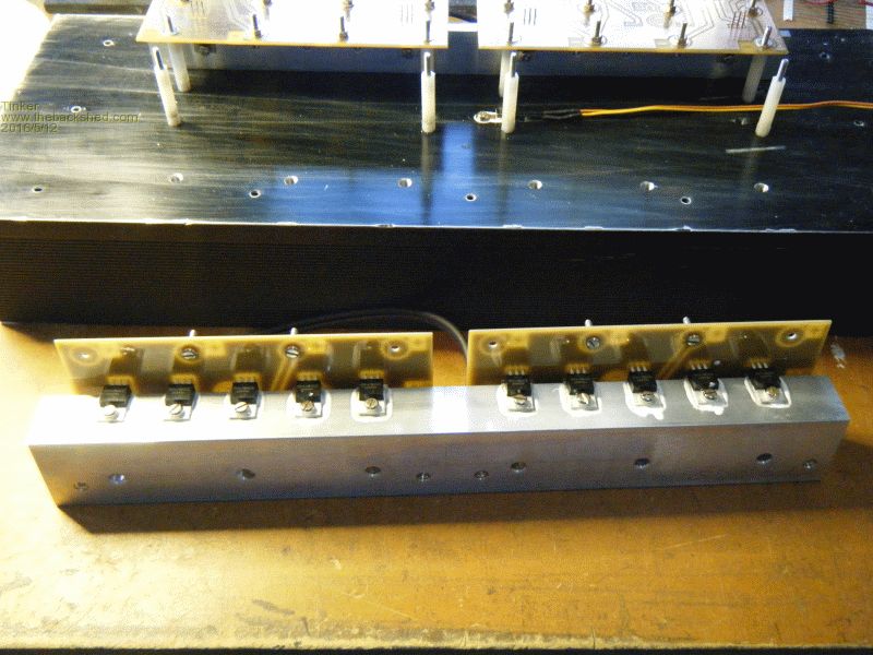
This is one of the two sub heat sinks. My design idea requires the mosfets to be fully insulated from the heat sink. I used mica washers and plastic screw insulators. I also tested each one with a home made 80V test lead (just a LED with a series 5k6 resistor) as testing with the usual low voltage multimeter buzzer would not do in this 50-60V application. Plenty of heat sink compound at the mica washers and between the sub and main heatsinks. A strict sequence of assembly has to be employed with this idea. Also the holes have to be drilled quite accurately so everything lines up on assembly. A hint if anybody is thinking of copying this; make sure holes drilled into the main heatsink go in between the fins. It is so much easier to tap a through hole than a blind hole. I used 6 x M5 hex bolts to screw the sub to the main heat sink. These are accessible from the side of the PCB above them, other screws would not be. Here are the 4 boards in place with the gate leads soldered on: 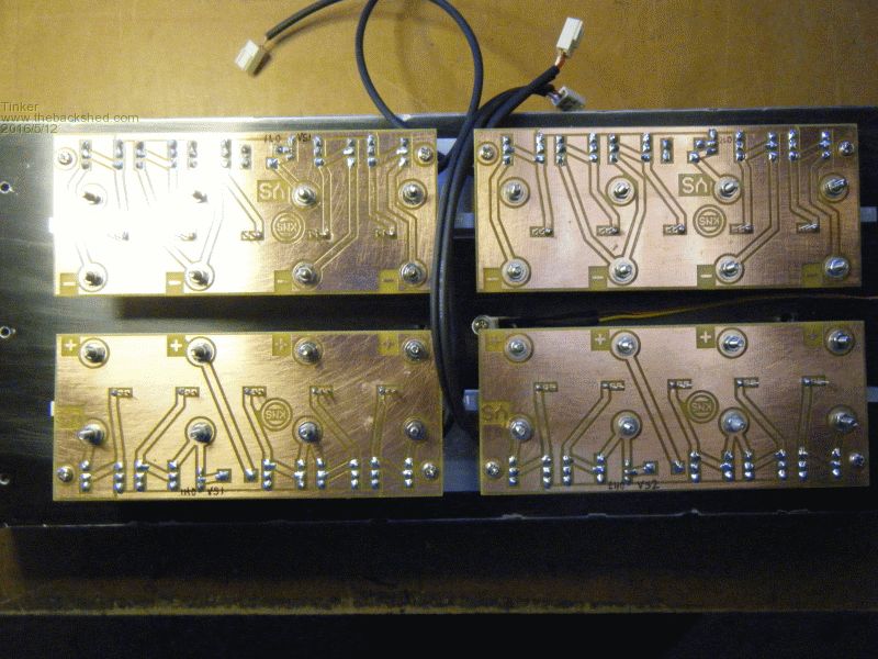
Now I'm waiting for the big capacitors, one lot arrived apparently but had been returned to the sender.... I never got notified by the post  Klaus |
||||
oztules Guru Joined: 26/07/2007 Location: AustraliaPosts: 1686 |
Fiendishly good engineering there Tinker... It deserves to work very well.... there's plenty of good work in there, and significantly better than I would try and do. Ordered more caps today $4.39 each supposedly panasonic... with a rubycon picture?? We'll see what turns up. Gizmo..... its been more than 7 months of operation.... how is the $650 dollar unit running. Assuming the latronics will run for 10 years, you only have to eek out another 4 of 5 months to pro-rata pay for this one.... Mine has been in operation for a near 2 years now... no sign of problems as yet... amortized to about $200/year so far. Don't think I will be springing for a "real" inverter any time soon, nor do I see this one falling over soon... seems rock solid as ever. .....oztules Village idiot...or... just another hack out of his depth |
||||
Grogster Admin Group Joined: 31/12/2012 Location: New ZealandPosts: 9307 |
Oz and Tinker - Rather then using multiple TO220 MOSFETS, is there any reason for not using a lesser number of much gruntier MOSFETS? Something like the IRFP4368PbF, which is a 72v MOSFET with a S-D current rating of 195A continuous(350A silicon limited surge), a tiny 1.85 milli-ohms Rds(ON) resistance, and up to 520 watts power dissipation. More then twice as grunty as the IRFB4410Z TO-220 device. Four of those should be able to drive the toroid directly, and you have a much smaller, simpler PCB design. Sixteen less transistors to fit, in other words, and that's a lot of transistors. 50pcs of the TO-220 part as linked to above is US$27. 5pcs of the TO-247 4368 part is $10.45 at AliExpress. I could well be missing something...... Smoke makes things work. When the smoke gets out, it stops! |
||||
oztules Guru Joined: 26/07/2007 Location: AustraliaPosts: 1686 |
only the price to the power handling. You will want more than 4 in there... your forgetting about peak currents. Probably want 3 per bank to be safe (ish). Their surge current is over 1000A, and the little 220 are 560A I use 6 per bank on a full inverter..... thats 3000A/bank surge. The continuous current is made up of very very much higher skinny peaks... so 5kw may only be 100amps cont, but the pulse width may be only 20% duty.... so 500 amp peaks continually.... thats why the caps are there... and so big. For the 5kw unit I make, we have 60000uf... and thats why... to cover the peaks, and thats why they heat up too, as when we have power surges in the 10-15kw region, the pulses are horrendous. If you look at my electric fencing units, you will see we can make 250,000 watts for each 1 second pulse.... from a lowly 50uf capacitor..... time is the key. So 3 per bank would be acceptable, but thats getting expensive for no real gain. I do like TO247 package, and I do think the TO220 is just a toy..... but they prove me wrong all the time..... they just work fine. So it is only cost that is the reason we use 24 TO220 fets in the full blown units, certainly for 2kw limited units, 4 TO247 would be probably ok.... even then keep the CT cap small to limit the peaks with faster response times. ................oztules Village idiot...or... just another hack out of his depth |
||||
Grogster Admin Group Joined: 31/12/2012 Location: New ZealandPosts: 9307 |
Understood. Thanks for the excellent explanation. I did not think that the TO220 transistor type and part number was chosen out of the blue, and I expected that people had researched that before me, I was just wondering why when you can get some pretty beefy transistors, why you guys used so many smaller ones. 
Makes sense if I would still need three per bank for safety - you'd be getting more expensive then on TO247's then just doing it the TO220 way in the first place. Thanks for clarifying that for me.  Smoke makes things work. When the smoke gets out, it stops! |
||||
| Tinker Guru Joined: 07/11/2007 Location: AustraliaPosts: 1904 |
A few days ago the ferrite E-core which I had ordered on e-bay (from Bulgaria) arrived. By sheer coincidence yesterday I found an alternative to this US$25.- option when I dismantled a junked 2.5KW Fronius IG 30 grid connect inverter to see if any useful parts were inside. And I spotted this transformer: 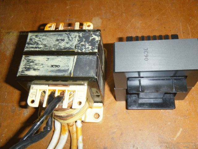
It has the same number stamped on the core as the newly purchased E core pictured next to it. So I assume its magnetic properties are similar. But its a dual (stacked) core with a considerably bigger (875mm sq against 529mm sq)cross section. I think that should work even better, bigger is better I think  . .
Unfortunately this transformer was lacquered solid so not easy to get apart. But I knew just the trick. I required a big opening screw top container where the whole transformer could fit inside. Found a plastic one and tested first if acetone attacked it - it passed this test. So about 5mm acetone was poured in, the transformer followed (it remained above the acetone pool on a central raised part). The idea is to soak the lot in acetone fumes overnight, hoping that softens the lacquer, which it did. Next morning the first job was to knock out the presspahn piece that jammed the bobbin against the core: 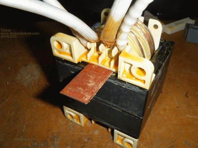
This came out quite easily with a 1mm thick brass strip being carefully tapped in from one side. Now the bobbin was loose and I had to separate the two E cores: 
I used an old swiss army knife and tapped its blade carefully in the groove where the cores met. Ferrite is *very* brittle so great caution is required to do this. But they popped apart relatively easy. Next the E core halves needed to be separated. There is no groove for the knife there and the mating surfaces are ground flat with a very thin plastic shim between. Carefully knocking on the whole core with a fist sized lump of wood eventually popped the halves apart with no damage. 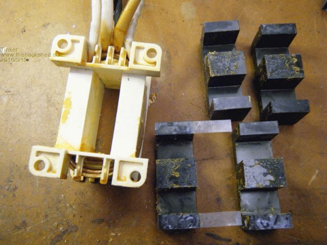
The HF litz wire windings came off quite easily, there were not many turns anyway. Now, after a little cleaning, I had another E core to try out. 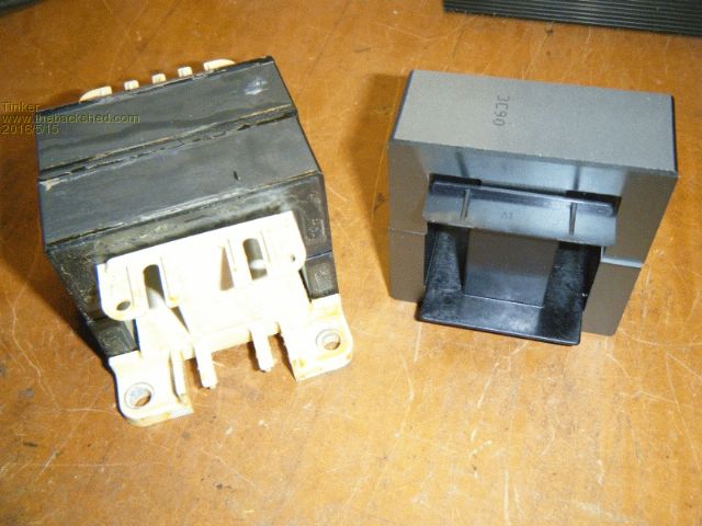
The winding area on this bobbin is a little bigger, 14.5 x 35mm against the 11 x 40mm of the purchased item. I will be using enameled copper strip wire and should be able to fit 4 turns (3 in hand)giving around 70mm sq total copper section on it. The best part about this bobbin are the mounting holes, no need to make a fancy collar to secure this ferrite choke. I will secure the core halves together with epoxy once the correct plastic shim size had been found experimentally. There is also a smaller ferrite core transformer in these inverters which might be useful. Klaus |
||||
| Tinker Guru Joined: 07/11/2007 Location: AustraliaPosts: 1904 |
OK, more progress pictures. The 6 x 10,000uF/100V capacitors had arrived so I could solder them onto the copper strips. This turned out to be trickier than anticipated, a 25x1.5mm copper strip sucks heat away really fast. I used a 80W non temperature controlled iron which is a bit on the small side. I think a 100 or 125W iron would be much better. Anyway, I managed after giving the iron a short reheat spell after each solder joint. 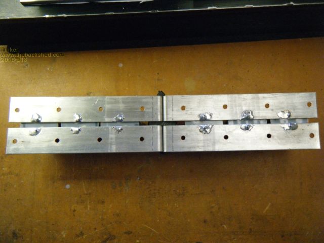
I made plastic disks to fit in between the cap bottom and the copper strips for extra insulation. I really do not want the cap housing short out the battery supply. To avoid cooking the cap insides the copper next to the cap terminals was heated until the solder flowed freely, only then the terminal was soldered. This produced joints looking a little messier than as is my standard but making sure its not a dry joint. Next was to fit the capacitor assembly to the 4 PCB's. Despite me aligning the copper strips carefully while soldering the caps some of the screw holes used to mount the assembly required a little visit with a small round file, I suppose that is inevitable with this method of mounting. Now the drain and source pins of each Mosfet were bent over their respective copper strip and soldered. Again, a bigger wattage soldering iron would have been nice. 
So, after fitting the 230V board and EGS002 motherboard everything was ready for testing. I had the EGS002 board unplugged for this stage. First off check the 55V to 12V DC to DC converter - OK Next check the 5V supply - OK Then set the current overload potentiometer for shutdown at 8KW. This setting is very easy to change later should it be required. 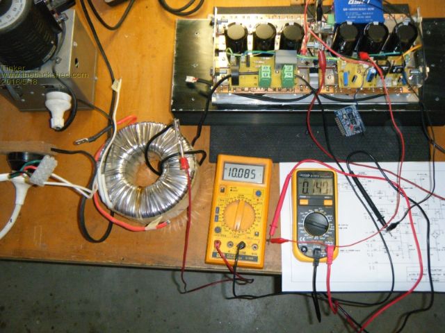
It required 10A AC to pass through the C/T hole. My little test toroid (1.2KW) was used to get the 10A. A single added turn to the toroid passed through the C/T hole and was shorted with a 10-A AC amp meter. The toroid's 230V winding was fed by a variac transformer, this then just required increasing the primary voltage slowly until the meter showed 10A. I set the current adjust pot for 0.15V at the EGS002 current sense input. Now my inverter is ready for load testing, which I will do tomorrow. Klaus |
||||
| Tinker Guru Joined: 07/11/2007 Location: AustraliaPosts: 1904 |
It worked, me is very happy now 
I used the same small toroid shown above to test it and this was only good for about 1Kw. The driver board shut down promptly when I connected a 2.4Kw load as the AC output voltage just collapsed with that overload. The dual stack big toroid should fix that limitation  . .
The AC voltage adjusts nicely and the soft start switch works perfectly. Thanks oztules for pointing me in the right direction with that one. Further work on this project will be on hold for a while now as I'm doing the grey nomad thing until the winter is over. Klaus |
||||
oztules Guru Joined: 26/07/2007 Location: AustraliaPosts: 1686 |
Damn good when a plan comes together.. shame the testing has to wait. ....oztules Village idiot...or... just another hack out of his depth |
||||
oztules Guru Joined: 26/07/2007 Location: AustraliaPosts: 1686 |
Tinker... you need to read this http://www.fieldlines.com/index.php/topic,149011.msg1037697.html#msg1037697 ...........oztules Village idiot...or... just another hack out of his depth |
||||