| |
  Page 3 of 6 Page 3 of 6   |
| Author |
Message |
oztules

Guru

Joined: 26/07/2007
Location: AustraliaPosts: 1686 |
| Posted: 12:02am 15 Jun 2016 |
 Copy link to clipboard Copy link to clipboard |
 Print this post |
|
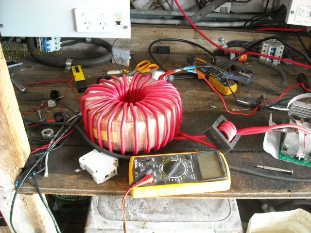
I reckon probably 110 turns for 240v secondary .... double core of your 190, 100, 70. cores@2.25v/turn.
Primary of 26v so 12 turns of 35mm or better wire depending on how much your after.
50mm will give you a serious unit indeed.
You will like the 100mm hole compared to 90mm... every mm counts, as I think Glen alluded to.
I suspect it is with some relief you don't have to face another core right now, they take it out of me I know that.
That photo of near 5kw was done with a single core. Interesting that the voltage did not sag even at those levels.
It does however, boggle the mind to even consider 15x2mm wires going through that core at the same time..... just can't see it.
..............oztules
Edited by oztules 2016-06-16
Village idiot...or... just another hack out of his depth |
| |
Madness

Guru

Joined: 08/10/2011
Location: AustraliaPosts: 2498 |
| Posted: 12:57am 15 Jun 2016 |
 Copy link to clipboard Copy link to clipboard |
 Print this post |
|
Yeah unwinding them is a tedious job, I start to go numb between my shoulder blades. No doubt winding it is going to be a lot slower process, I rewound my 8KVA 12 wire generator a couple years ago, that was a tedious, fiddly and difficult job. I expect this will be every bit as much fun.
Down the track I will run Air Conditioning off the solar, during hot sunny days I will have power to spare. So when that day comes I will get above 5 KW for periods of time. Also I see there is a 3 phase version of the chip that drives the inverter, I am thinking of using 3 single cores like you did here. That would give around 9 KW continuous, I would be using it for lathes etc. Being able run everything without needing a generator is the ultimate off grid home.

There are only 10 types of people in the world: those who understand binary, and those who don't. |
| |
Grogster

Admin Group

Joined: 31/12/2012
Location: New ZealandPosts: 9308 |
| Posted: 01:12am 15 Jun 2016 |
 Copy link to clipboard Copy link to clipboard |
 Print this post |
|
Oz - for a core with 90mm inside diameter, 190mm outside diameter and 120mm in height, how many turns would I need of two in hand 2mm wire for a 240v secondary, assuming at least a 48v primary and up to 6kW load?
I can get a toroid core from a transformer factory in NZ to those specs for only $200 or so, then just wind it myself as per your articles etc, but that would still be much cheaper then freighting from Australia(cos these things are HEAVY).
I might rustle up a schematic of your board then. Can you post a high-res image rather then the small one, or the one cut up into four bits? If you post your image as a GIF here rather then a JPG, the forums won't squish the image.
Smoke makes things work. When the smoke gets out, it stops! |
| |
Madness

Guru

Joined: 08/10/2011
Location: AustraliaPosts: 2498 |
| Posted: 01:18am 15 Jun 2016 |
 Copy link to clipboard Copy link to clipboard |
 Print this post |
|
112 turns, can you get the core made with a 100 mm hole?Edited by Madness 2016-06-16
There are only 10 types of people in the world: those who understand binary, and those who don't. |
| |
Grogster

Admin Group

Joined: 31/12/2012
Location: New ZealandPosts: 9308 |
| Posted: 01:23am 15 Jun 2016 |
 Copy link to clipboard Copy link to clipboard |
 Print this post |
|
Probably - they roll-up the toroid however you want the core.
So I would say yes.
100mm would give more room to move in the winding, but how does that affect the outside diameter? Does that go up to 200mm for example, and keep the same 112 turns?
Smoke makes things work. When the smoke gets out, it stops! |
| |
Madness

Guru

Joined: 08/10/2011
Location: AustraliaPosts: 2498 |
| Posted: 01:33am 15 Jun 2016 |
 Copy link to clipboard Copy link to clipboard |
 Print this post |
|
As Oz was saying you need the big hole to get all the wires in and also it is easier to work with. If they are rolling it then they should be able to go as far as you want on the outside. The cross section area of the core is what effects the number of turns, 1 volt for every 2800 mm2. The core size you gave would be 50 (difference between inner and outer radius) * 120 = 6000 6000/2800 = 2.142 240/2.142 = 112
100 id and 200 od would give exactly the same cross sectional area so still 112 turns.
There are only 10 types of people in the world: those who understand binary, and those who don't. |
| |
oztules

Guru

Joined: 26/07/2007
Location: AustraliaPosts: 1686 |
| Posted: 02:02am 15 Jun 2016 |
 Copy link to clipboard Copy link to clipboard |
 Print this post |
|
Grog, Mad is all over this now, his figures are correct... poor soul has got the bug.  ... aim for 26v primary for 48v... these things have limited dynamics. The PJ can be 30v... bit less primary current. ... aim for 26v primary for 48v... these things have limited dynamics. The PJ can be 30v... bit less primary current.
That (2800/v/t) is a conservative number I came up with from experience with these things. It is for 50hz. There is room for movement, but I have found that that formula seems to make transformers with decent magnetising current ( 20-40 watts ) and head room..... like everything I do, it is probably not technically correct, but works well in the real world.
This link has pics that enlarge. They were screen grabs only
http://www.anotherpower.com/board/index.php/topic,1116.msg12314.html#msg12314
If you can read protel pcb then I can give you the pcb file for it as well.
The pdf from the prog is on that link as well.
It is close to the published stuff from the eg8010 data sheet applications.
The pdf from the pcb
These 8010 chips use ( I used) unipolar spwm, so the transformer will be noisier than the pj, which now use bipolar spwm.
I will experiment with bipolar and see if the temp stays cool, and may move to that if all ok.... but really thats only nit picking... unless you work right next to it.
It makes no more noise at idle than at 5kw at the moment, but if we switch to 23khz on both legs, then it will get rid of the low freq hum from the square waves on one side of the bridge.... time will tell.
.............oztules
Village idiot...or... just another hack out of his depth |
| |
Grogster

Admin Group

Joined: 31/12/2012
Location: New ZealandPosts: 9308 |
| Posted: 04:08am 15 Jun 2016 |
 Copy link to clipboard Copy link to clipboard |
 Print this post |
|
@ Madness - Thanks. Calculating the turns is confusing for me.  I will have to take your examples and do some of my own and compare notes. I would like to understand how that actually works. I will have to take your examples and do some of my own and compare notes. I would like to understand how that actually works.
@ Oz - The big image in that link shows the blue copper layer over the top of the silkscreen, so I can't read the component values. You CAN read the values in the four images that are sliced up into quarters. Do you have Gerber files for your board? I looked in the PDF, but that is just if you were making them at home and were to use the toner-transfer method or film positives etc. I am guessing that any PCB software you used, should allow exporting Gerber files.
Sorry if I am being a pain, but as you have done all the work on the PCB there....
I must say that I much prefer the new small transformer being used for output voltage feedback. The 8010 PDF, 002 module etc all using the rectified 240v from the secondary of the inverter, often in very close proximity to the low-voltage stuff, always made me uneasy. As there is no isolation from the mains there, should something fail short-circuit - make big explosion!!!  I guess that is not THAT likely with 100k resistors, but still, I didn't like that configuration or the idea of tying the high-voltage and low-voltage grounds together either....... I guess that is not THAT likely with 100k resistors, but still, I didn't like that configuration or the idea of tying the high-voltage and low-voltage grounds together either.......
I guess I am perhaps a bit over-cautious maybe, but I like separation standards between LV and HV stuff. 
Smoke makes things work. When the smoke gets out, it stops! |
| |
oztules

Guru

Joined: 26/07/2007
Location: AustraliaPosts: 1686 |
| Posted: 10:41am 15 Jun 2016 |
 Copy link to clipboard Copy link to clipboard |
 Print this post |
|
I too am more comfortable with separation, and it solved the problem. Opto isolators would be fine too I guess, and cheaper etc..... but I had heaps of those trannies laying about.
There is now tons of room between the ac and dc.
There are gerber output files... no idea how to use them, never interested me for bath tub boards. Happy to send you what there is though.
This forum does not allow unsupported files. 
They are posted on anotherpower.
EDIT: reloaded the ones on another power here:
They might actually work now..... 
http://www.anotherpower.com/board/index.php/topic,1116.msg12315.html#msg12315
The single pic is too small to display the parts, it need a zoom, then is too big... hence the 4 pics.
.............oztulesEdited by oztules 2016-06-16
Village idiot...or... just another hack out of his depth |
| |
Madness

Guru

Joined: 08/10/2011
Location: AustraliaPosts: 2498 |
| Posted: 01:04pm 15 Jun 2016 |
 Copy link to clipboard Copy link to clipboard |
 Print this post |
|
Hi Oz,
Are the PCB files for the FET board posted online some where also?
Thanks
Gary
There are only 10 types of people in the world: those who understand binary, and those who don't. |
| |
oztules

Guru

Joined: 26/07/2007
Location: AustraliaPosts: 1686 |
| Posted: 02:11pm 15 Jun 2016 |
 Copy link to clipboard Copy link to clipboard |
 Print this post |
|
ok Mad... here
http://www.anotherpower.com/board/index.php/topic,1116.msg12329.html#msg12329
..........oztules
Village idiot...or... just another hack out of his depth |
| |
Grogster

Admin Group

Joined: 31/12/2012
Location: New ZealandPosts: 9308 |
| Posted: 03:23pm 15 Jun 2016 |
 Copy link to clipboard Copy link to clipboard |
 Print this post |
|
Downloaded those Gerbers, but they won't import. I have a feeling they might be early-version Gerbers. They have to be Gerber 274-X these days, and your software may not do that version of Gerber if it is an older software.
Such is life..... 
Smoke makes things work. When the smoke gets out, it stops! |
| |
Madness

Guru

Joined: 08/10/2011
Location: AustraliaPosts: 2498 |
| Posted: 11:10pm 16 Jun 2016 |
 Copy link to clipboard Copy link to clipboard |
 Print this post |
|
After a few days sorting out problems with ants in pumps etc due to wet weather I have made some progress with the Torroid.
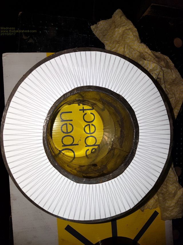
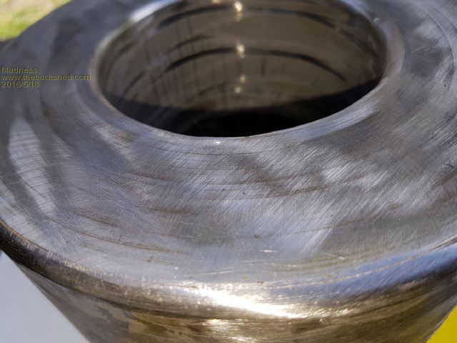
When unwinding the larger of the 2 I am working with the ribbon was not one continuous length. There was a piece just about right that came out and I added to the other to get the same OD. Took some out of the centre of the other, now they match. Now they are glued together, will round of the corners and fibreglass them in the morning and start winding when that is set.
I used Rhino Cad (free trial available) to make the paper guide for winding. It has 98 points that is the number of turns I need. It will go under the last layer of Mylar before I start putting the wire on.

Edited by Madness 2016-06-18
There are only 10 types of people in the world: those who understand binary, and those who don't. |
| |
oztules

Guru

Joined: 26/07/2007
Location: AustraliaPosts: 1686 |
| Posted: 01:04am 17 Jun 2016 |
 Copy link to clipboard Copy link to clipboard |
 Print this post |
|
brilliant idea.... you know exactly what you will end up with... Im liking this 
........oztules

Village idiot...or... just another hack out of his depth |
| |
Madness

Guru

Joined: 08/10/2011
Location: AustraliaPosts: 2498 |
| Posted: 01:32am 18 Jun 2016 |
 Copy link to clipboard Copy link to clipboard |
 Print this post |
|
Got my door stop cleaned up, edges rounded and ready for fibreglass. Has the glass on it now, doesn't look as nice. Waiting for it go off properly and then will clean it up and get started with winding it tomorrow.
Does anyone know where I can get 4 OZ Copper clad board at a reasonable price?

There are only 10 types of people in the world: those who understand binary, and those who don't. |
| |
Madness

Guru

Joined: 08/10/2011
Location: AustraliaPosts: 2498 |
| Posted: 02:22am 18 Jun 2016 |
 Copy link to clipboard Copy link to clipboard |
 Print this post |
|
Hi Oz,
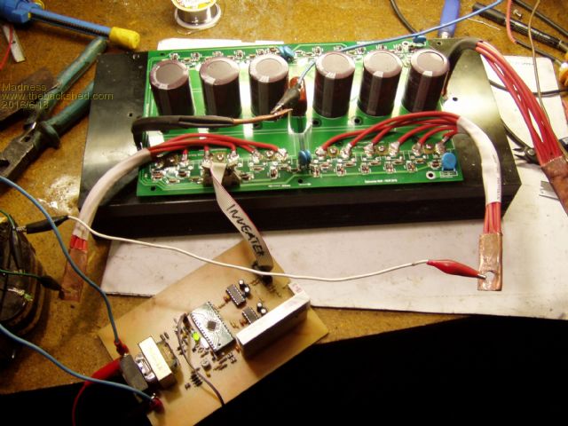
I see what you have done with Clockmans Power PCB. I was thinking how to use the heat sink off the Aero Sharp, had been looking what Antman had done. But when I saw your bodge (hats off to you for finding a way to just make it work) of that board to use the heat sink light bulbs came on.

From http://www.anotherpower.com/board/index.php/topic,1116.345.html
Just started slimming down Clockmans design, I reckon I can get it down to 100 mm wide. That would allow cutting a 100*300 mm hole in the top of the Aero Sharp case between the existing heat sink screw holes. Then the heat sink and PCB would fit straight in easily.
Also looking at mounting the Torroid in the same case, if I wind the primary with flat enamelled copper strip it could mount on what is currently the bottom with about 20mm clearance to the caps on the power PCB. Possibly also turn the lot on it's side so the heat sink is vertical and let natural convection cool the heat sink, or do you think it would handle the heat load in the normal horizontal position?
Doing all this then still leaves plenty of real estate for breakers and the Sine Wave PCB etc.
Gary
There are only 10 types of people in the world: those who understand binary, and those who don't. |
| |
oztules

Guru

Joined: 26/07/2007
Location: AustraliaPosts: 1686 |
| Posted: 12:14pm 18 Jun 2016 |
 Copy link to clipboard Copy link to clipboard |
 Print this post |
|
Yes, if you condense that board down to 100mm or less, and use the multi wire approach, you cold use normal copper, as the wiring goes direct to the current points.
I used 4mmsq wire, but 2mmsq would be ok for the transformer points if you used 12 wires... as you would be actually point to point wiring, the copper would only be used to connect the caps.
The fets are only clamped to the heat sink. with three screws/bank... very quick to on/off if necessary.
I may try to tidy this up a bit more.
It is currently mounted on an inspire heat sink, as is is wider than the aero, but the aero on it's side would make a very good unit. It would allow 120mm fans much easier as well, and a decent vertical heat path inside for the torroid.
For a 4kw unit, with a single core would do fine, and leave plenty of room for playing.
Clockmans board is very solid, but a slimmer one would suit the aero sinks, and normal thickness copper.
You will see where I was going to use three points for the transformer points, but went for using 6 of the solder points Clock provided...and used the copper on the board for the opposite fets, but direct wire would work every bit as well I think.
Will fiddle a bit with the next one, and watch you closely too.
Hell, there is some extraordinary talent out there amongst you lot.
...............oztules
Village idiot...or... just another hack out of his depth |
| |
Madness

Guru

Joined: 08/10/2011
Location: AustraliaPosts: 2498 |
| Posted: 06:00pm 18 Jun 2016 |
 Copy link to clipboard Copy link to clipboard |
 Print this post |
|
I am just a mere Minion in the shadow of Dr Nefario.
https://www.youtube.com/watch?v=ZF2yPLkElfE
There are only 10 types of people in the world: those who understand binary, and those who don't. |
| |
oztules

Guru

Joined: 26/07/2007
Location: AustraliaPosts: 1686 |
| Posted: 11:57pm 18 Jun 2016 |
 Copy link to clipboard Copy link to clipboard |
 Print this post |
|
Grogster, can you try these gerbers please.. from 99se design explorer.
http://www.anotherpower.com/board/index.php/topic,1116.msg12374.html#msg12374
............oztules
Village idiot...or... just another hack out of his depth |
| |
Grogster

Admin Group

Joined: 31/12/2012
Location: New ZealandPosts: 9308 |
| Posted: 01:17am 19 Jun 2016 |
 Copy link to clipboard Copy link to clipboard |
 Print this post |
|
Yes, I can import those ones - thanks. 
Smoke makes things work. When the smoke gets out, it stops! |
| |
| |
  Page 3 of 6 Page 3 of 6   |

