
|

|
Forum Index : Electronics : Building a new Inverter.
| Author | Message | ||||
| gpalterpower Senior Member Joined: 19/07/2009 Location: AustraliaPosts: 175 |
Hi Glenn The hole diameter is 80 -85 mm. Since my setup is 24v, would I need to use 25mm area cable as your system is 48v? Or do I need to go bigger? I hooked up a 60w globe and these are my findings. With the lamp hooked in series it didn't come on at at all. .. not even a glow! Some weird like scratching sounds within the toroid when connected and disconnected . Lamp in series in other winding ( inner). Lamp was half as bright.( 132v across lamp)....but this is the weird thing, with the lamp in series on the outer layer and dosent no glow, I connect the inner windings together it comes on bright..confused! Is this a charactist of toroidals or a problem inside? Windings are not shorted as there are separate ohm readings . I too believe it could be an earlier or maybe different model as yahoo suggests. Took a pic of the old label as for some comparison if you still have yours. May have binned by now! 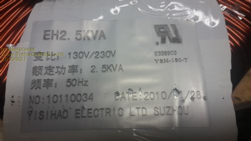
Marcus if it aint broke dont fix it!! |
||||
| Gizmo Admin Group Joined: 05/06/2004 Location: AustraliaPosts: 5078 |
Yep looks like there are two possible transformers used by the 2.5kw Inspire's. Either the 240v winding is on the inside, or the outside, of the 130v winding. I got lucky. Looking at your results. Remember the bulb is acting as a current limiter, we need it to protect things. You did bad things! When you connected the bulb up and it didn't light, then that was the 240v winding, this is expected. What you should have done then is measured the voltage across both windings and written them down. We need this later to work out the turns ratio. Bulb in series with other winding, half glow. Thats OK too, its the 130v winding, and by design limiting the voltage across the coil, so the bulb gets about 110 volts. If you measured it, there would be around 240v across the other winding during that test. When you shorted one winding and the bulb light up. Yep, its a shorted power supply and trying to draw as much current as it can. bad. dont do that. Go back to your first test, and use a good multimeter to measure the voltage across both the 240v and 130 windings while the bulb in is series with the 240v winding. The 240v winding will be down a couple of volts, this is dropped across the bulb. For a 24v inverter, you need less turns, thats good, but you should go for heavier wire, 35mm or 50mm ( two 25mm's together ) Glenn The best time to plant a tree was twenty years ago, the second best time is right now. JAQ |
||||
| Gizmo Admin Group Joined: 05/06/2004 Location: AustraliaPosts: 5078 |
Heres a basic test circuit. 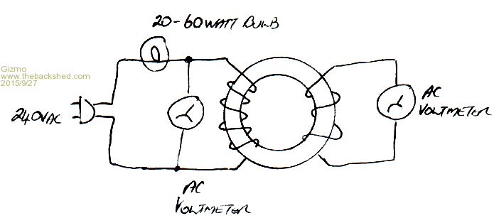
Now in this case, because we dont know how many turns are on the primary or secondary, you need to wind a test coil. Wind say 5 turns of wire ( any old wire ) through the transformer, and connect a multimeter across it. Then connect up the 240v winding like above, with the bulb in series. Power it up, and take note of the multimeter readings on the test coil, and check the multimeter on the primary is somewhere around 230v, give to take 10 volts.. Say the test coil measured 10 volts, we can work out the ratio's. 10v / 5 turns gives 2 volts ac per turn. Glenn The best time to plant a tree was twenty years ago, the second best time is right now. JAQ |
||||
| gpalterpower Senior Member Joined: 19/07/2009 Location: AustraliaPosts: 175 |
ok. Did some testing. With light in series on 240 windings ( outer) voltage was 222v and the output on the 130v (inner) windings was 124. With light in series on 130v winding , (inner) voltage was 134v and the output on the 240 was 237v. With light in series on 240 winding and 5 turns of cable, output was 7.5v. Hope this enough info to work things out. Thanks for you help. Marcus if it aint broke dont fix it!! |
||||
| brucedownunder2 Guru Joined: 14/09/2005 Location: AustraliaPosts: 1548 |
Marcus, search brucedownunder2 "modifing my power hungry inverter" , it's 48 volts , but it's fairly similar to yours and glenn's project. Bruce Bushboy |
||||
| gpalterpower Senior Member Joined: 19/07/2009 Location: AustraliaPosts: 175 |
Hi Bruce, Thanks for the link. checked out your hungry inverter post. Interesting reading and job well done on increasing the efficiency of your inverter . Is that the same toroid from an inspire 2.5? Looks bigger than mine. Maybe that's just the pic. So were you one of the lucky ones who got the easy to wind toroid along with Glenn ? Seems I missed out in that department and may have a liiiittle extra work to do. I'm thinking of removing the outer 240 layer and seeing what's inside and if I can utilise that somehow, then wind the new primary. I will be looking to find and use some welding cable. Looks difficult pushing that 25mm wire around corners Couldn't find the thread in energy matters but would love to read thru it. Typed in "modifing my power hungry inverter" , but just drew a blank . Is it under a different name? Marcus if it aint broke dont fix it!! |
||||
oztules Guru Joined: 26/07/2007 Location: AustraliaPosts: 1686 |
https://forums.energymatters.com.au/solar-wind-gear/topic3344.html This was a reasonable size thread..... until Bruce started into it on page 16 from memory... it is up to page 123... bring a cut lunch... Bruce's fault I'm sure.... .........oztules Village idiot...or... just another hack out of his depth |
||||
| gpalterpower Senior Member Joined: 19/07/2009 Location: AustraliaPosts: 175 |
Thanks Oztules for that link. Yesssss.. some serious reading there!! Had a look the other day. Packed lunch wasn't enough..... more food more reading. Interesting thread with valuable info though. This project has been on the back burner for a couple of weeks now due to other commitments, but thinking about it today what Gizmo suggested earlier It may be feasible to wind the new primary within the torroid as it stands and leave the other 2 windings in place. Been doing some calcs and may be possible to wind a max of 23 turns of 32mm cable. approx (11mm diameter, 455 strands of .3) which makes it fairly flexible especially when going around corners. The inside diameter is 85mm. So firstly would 23 turns be enough. If I had to place a few more turns it might begin to look a bit untidy. Any thoughts welcome. Marcus if it aint broke dont fix it!! |
||||
| Gizmo Admin Group Joined: 05/06/2004 Location: AustraliaPosts: 5078 |
One thing I learnt when I wound my transformer is the wires wont fit as well as you think. If the maths tells you you can fit 10 turns, when you go to wind it, you will only fit 8. Just something to be aware of. Glenn The best time to plant a tree was twenty years ago, the second best time is right now. JAQ |
||||
| brucedownunder2 Guru Joined: 14/09/2005 Location: AustraliaPosts: 1548 |
hI Marcus, i found that the 25mm square building cable I used was very tight towards the final windings. i spoke to other guys that had the same problem ,but that assured me that I could ignore the appearance and get the turns done anyhow. i actually had to really force the last few turns into the hole wherever I could find a small space.. iT all works electrically , just don,t show anybody,lol. butcher Bruce Bushboy |
||||
oztules Guru Joined: 26/07/2007 Location: AustraliaPosts: 1686 |
No Marcus... you will need more turns as your idle will be too high because of saturation in the core.... I assume you mean 48v system. We want about an 8:1 ratio, and you looking at about 1.1v/turn for your tranny I suspect... so 240/8= 30 turns. Better idle current would be if you increase the secondary to 250v or more, and the primary would be 31 turns. If you look at the magnetisation curves, you will see it gets very non-linear up near saturation. The manufacturer will likely sidle up near saturation to keep the steel/copper costs down, so if you can distance yourself away from the top of the curve, you will probably get very good returns on your extra turns. Taken to extremes this gets diminishing returns, as the copper losses go up instead, but another 20 turns will get results worthwhile.... not necessary, but nice.... particularly if you push the unit hard for longer times.... as you start to push hard, you may get clipping if you don't have enough head space, particularly if the battery voltage is down.... same watts needs more amps in that case. Do get rid of the windings you won't be using, let the heat out easier, and you will need the winding space. You boys are using thin wire compared to most of us, so use temp sensors on the heatsinks and transformer during the run in phase, to get an idea of your limitations.... ie stay below the 3kw mark for continuous duty... regardless of your board size.Your surge will be fine, for 5kw or so, but continuous is compromised by using only a single with thin primary. My next one will be a eg8010 unless Glen beats me to it.... which won't be hard. .............oztules Village idiot...or... just another hack out of his depth |
||||
| Gizmo Admin Group Joined: 05/06/2004 Location: AustraliaPosts: 5078 |
Yes Oz I've ordered a eg8010 off ebay, $12 including the LCD, gets here in 2 to 4 weeks. It looks very promising, basically the brains of a home made sine wave inverter, just add a few caps, power mosfets and transformer. I was thinking, the module could be used to convert a retired computer UPS into a little sinewave inverter. A lot of 300VA and 600VA UPS's get put into storage ( or dumped ) when the battery fails. These have most of the components to build a sine wave inverter, just add a EG8010, a bigger heatsink for the MOSFETs, and a fan. Glenn The best time to plant a tree was twenty years ago, the second best time is right now. JAQ |
||||
| gpalterpower Senior Member Joined: 19/07/2009 Location: AustraliaPosts: 175 |
Thanks Gizmo, Bruce and Oz, Yep... Makes perfect sense to remove the outer winding. It will definately make it easier to wind on the new primary and help with the cooling capability later. Started unraveling it today. There is 2 in hand although they were wound individually . First layer off and I counted 170 turns of 1.9mm dia wire. The hole now is 85mm. After the second layer was removed the hole is 93mm. 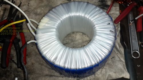
Getting down to the nitty gritty and after removing a layer of blue insulation I uncovered a band of copper that is connected to the earth lead ...always wondered where those earth leads went to? Now I understand if there is a fault in either winding will just go to earth. Duh! 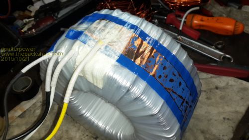
After removing more insulation I uncovered the start and finish of the original primary. It is 3 in hand of 2.25 mm dia wire which equates roughly to 12 sq mm. 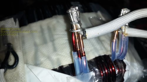
. Im not sure how many turns there are of this but I was wondering if there is some way I could utilise this or part of this 3 in hand wiring to become my new secondary. Any ideas welcome Oh BTW Oz. It is a 24v system that im building. Regards Marcus if it aint broke dont fix it!! |
||||
oztules Guru Joined: 26/07/2007 Location: AustraliaPosts: 1686 |
So, you have uncovered the 130v winding.... and it is substantial. Yes you can utilise it if you wish, it is the first 130v of your 240v winding. From your figures, you are about 1.4v/turn, you need another 110-120v so another 85 turns are needed of two or three in hand... 1.9mm wire. This will be over the top power wise, but never too much really. 2 in hand will be enough for 3kw. 240/170=1.4v/turn for that core @ 50hz. For space, if you can peel off one layer of the 130v winding it would not be detrimental for your power, and give you more space to wind the next 85 turns on. If you were very cheeky, you could split the winding up ( hopefully they are insulated from each other internally). For a 3kw unit I could live with a one in hand 2.25mmm winding. If you were to lose one in hand, and series the other two, you would have 260v secondary, one in hand to use, and more space for your primary. Primary for 24v would be about 1/16th of your secondary... 260/16=16v .... so 16/1.4= 11 or 12 turns of welding cable.... 50mmsq or more. If your not going to run this hard for extended periods, this should be sufficient, and save a heap of work..... or strip it all off, and start again with 170 to 180 turns of two in hand for the secondary.. epoxy as you go, and it will be silent as well as virtually indestructible. Remember, torroids are by far the best transformer, but they are wound with no enamels or other materials in the windings... so vibration is real. Most torroids ( yes...even in latronics and SME stuff) fail from inter winding breakdown, and arcing. Normal transformers never do.... this is because vibration from the MMF eventually finds a weak spot, and the insulation breaks down. Normal transformers usually fail from o/load because something else has failed... Luckily it is not rampant, but if a torroid is to fail, that will be the usual fault, and the reason for it....... so potting each layer makes a difference to expected longevity and noise. The copper layer is a shield... less RFI in sensitive equipment, not a safety concern. ...............oztules Village idiot...or... just another hack out of his depth |
||||
Grogster Admin Group Joined: 31/12/2012 Location: New ZealandPosts: 9308 |
Have you(or anyone else) gone down this road before? Certainly looks like an affordable method for lower power use. Is there any reason you can't just use a UPS in permanent-reverse with a much bigger battery? This is NOT how they are designed to work(long-term), so there may be issues with that idea - I am just throwing the concept out there.... Also, I am guessing that most of those 300/600VA UPS's are square-wave or modified square-wave, not sine-wave. However, by using the eBay module and tranny from the cheap UPS as you say....... I think I will look into this for experimental reasons. Smoke makes things work. When the smoke gets out, it stops! |
||||
| yahoo2 Guru Joined: 05/04/2011 Location: AustraliaPosts: 1166 |
Makes me think I should park a couple of torroids on the shelf for spares, I haven't seen a latronics or selectronics with a busted transformer yet, I guess that wont last. I'm confused, no wait... maybe I'm not... |
||||
| Gizmo Admin Group Joined: 05/06/2004 Location: AustraliaPosts: 5078 |
Hi Grogster The down side to the UPS for long term use is its E core transformer. Idle current would still be higher than if it was a nice toroid. But as a backup inverter it would be OK. A UPS would supply most of the parts needed. Transformer, mosfets, case and external connectors. Yes most of the UPS's I've seen are modified square wave, very few are true sinewave. Glenn The best time to plant a tree was twenty years ago, the second best time is right now. JAQ |
||||
oztules Guru Joined: 26/07/2007 Location: AustraliaPosts: 1686 |
Hopefully you will never need them. They may sit on the shelf forever. If you unwind torroids, you will be amazed at how they push the wire insulation to the limit..... with tight, side by side and across positions of the wire at different potentials ( usually one layer away in emf... 100v?). Most times, particularly in the smaller ones, they do not even have inter layer mylar wrap.. except for primary/secondary isolation. I have had one Latronics and one SME with torroid breakdown over here in just over a decade.... not common, but happens. I wind them like this: http://www.anotherpower.com/board/index.php/topic,1044.0.html It is amazing at how small the failure rate is when you see how they wind them..... at least you end up with pristine wire when you unwrap them... no lacquer or any other material sticking to the wire. ..... oztules Village idiot...or... just another hack out of his depth |
||||
| yahoo2 Guru Joined: 05/04/2011 Location: AustraliaPosts: 1166 |
Hi Oztules. I meant I should find some aeros or inspires and have a couple of DIY torroids around in case an inverter that has been scrapped and replaced with a new one ends up in my shed. I spotted a w7 powerstar gathering dust the other day that might make a good first project to get my eye in. thanks for the link, your post is a lot easier to understand than my handwritten scribblings.  I'm confused, no wait... maybe I'm not... |
||||
| gpalterpower Senior Member Joined: 19/07/2009 Location: AustraliaPosts: 175 |
Thanks OZ , So there's a couple of way I can do this. The quick way out would be like you say to separate the 3 in hand , series 2 together and disregard the third. I'm assuming that would give me a 3 kw with not much room to spare....... If some one has the toaster on and the fridge cuts in at the same time someone else is boiling the jug for a cuppa....then the inverter IS TOAST. I would like to run the house if that's feasible so Im thinking of just continuing on with another 85 turns of 3 in hand of 1.9. Is that overkill or is 2 in hand enough to do the job and what sort of output could I expect? Could another way be with the 3 in hand , separate one and wind another say 110 turns in parallel with the single with 2.25 and then series with the other 2 in hand winding. The only drawback is that im only guessing with amount of turns there are and may cause some imbalance and overheating when in a full load scenario. Just a thought! Marcus if it aint broke dont fix it!! |
||||