
|

|
Forum Index : Microcontroller and PC projects : Maximite with TFT made simple
| Author | Message | ||||
jman Guru Joined: 12/06/2011 Location: New ZealandPosts: 711 |
TZAdvantage Thanks for the info I had assumed that was the case. I eventually found a data sheet that included the touch screen So I can happily report that the 5" Innolux AT050TN33 works with touch I have been testing the beta TFT firmware from Geoff and apart from the Config LCD command all seems to be working fine. A small change from the original firmware is the TouchVal command this was Touch Value in the original TFT firmware Regards John |
||||
| Zonker Guru Joined: 18/08/2012 Location: United StatesPosts: 761 |
Thanks Jman & TZ for the info..!! Time to get out the wallet an do this thing... |
||||
| Zonker Guru Joined: 18/08/2012 Location: United StatesPosts: 761 |
Good evening Gents..! I ordered the displays and have them at hand. Was looking for a display interface and ended up using the NHD-FFC40 from Newhaven Displays. One thing I like about the board is the small CAP areas it has. I am trying to create a "smaller # of wires" interface for the display back to the MM processor. I downloaded the PDF doc's for the 5" Innolux AT050TN33 display unit and wanted to make sure where pin 1 is located. Large View showing interface board leading to 16 pin IDC connector... 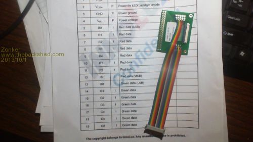
I looked through the doc's and can't seem to find absolute proof of where pin 1 is. I looked on the board's 40 pin display connector and it seems to indicate that pin 1 is on the left side. I think I see a small marking on it... 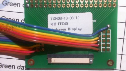
Jman, if you could confirm this before I hook it up all wrong, I would feel better about proceeding with the rest of the wiring... The next part will be what MM device to use to drive it. Jman, I read that you had used the UBW32 board to create your prototype unit, and since I do have one, would think creating a proto board for the UBW32 and wiring it to the 16 pin IDC connector going to the Newhaven board should work ok. Could you possibly post some info on your prototype wiring or schematic to go by.? It would save lots of time on this end. Thanks in advance for any help on this..!! I was also wanting to try to interface the display to the ColorMax 1 Board that I have been using to build the first EIS project prototype from. I have been using the touch displays from 4-D systems on a MM serial port to form the user interface. If I could modify the ColorMax board to work with the 5" display directly, I could still use it as a final prototype demo unit. However, I can't seem to find any schematic information on this board posted here on The Back Shed. I am not sure if you could do the proper changes with out really hacking it up anyway... I have downloaded the schematic set from Bovist to look at and am trying to get a Eagle-CAD based schematic of the new MM TFT board started. I was wondering if anyone else is doing the same thing.?? It would be far easer to just buy a ready made board than create the PCB from scratch... Not sure if anyone is trying to create one. Anyway, Thanks Gents for all the help.!! I have limited time in the evenings to work on this project, so getting a properly laid out PCB built and working is going to be a while... |
||||
jman Guru Joined: 12/06/2011 Location: New ZealandPosts: 711 |
Hi I just used the schematic from Bovist and made a little perf board with the extra bits on 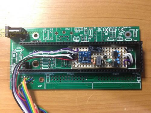
I modified the UBW32 adapter PCB to accommodate the START_HLINE This way the Pin on D2 remains TBS Link 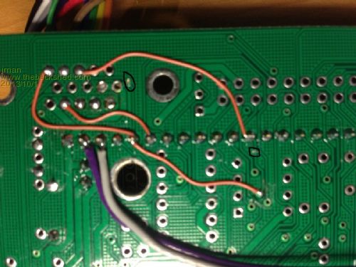
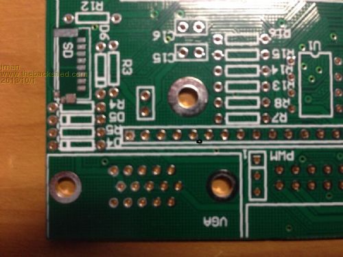
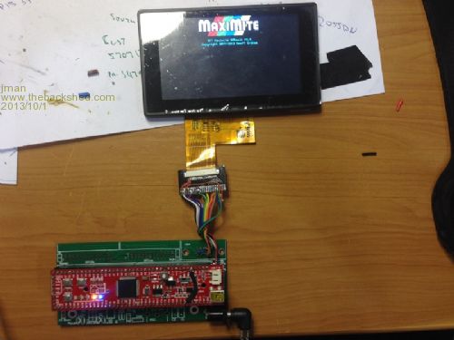
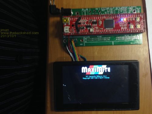
Both LCD's I have Pin 1 is on the left as below 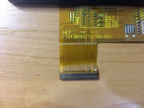
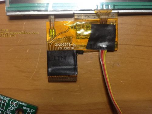
Hope that helps Regards John |
||||
| Geoffg Guru Joined: 06/06/2011 Location: AustraliaPosts: 3194 |
I have created a webpage where firmware and updates for this version of the Maximite can be found: http://geoffg.net/tft-maximite.html John (and anyone else who has a pre release version of the firmware), at the bottom of this webpage is the latest version (since yesterday) so it would be worthwhile reflashing with it. Geoff Geoff Graham - http://geoffg.net |
||||
Raros Regular Member Joined: 06/02/2012 Location: ItalyPosts: 55 |
Thanks. Great Geoff and Carsten. 
P.S. The link to the manual is wrong this download the MM_TFT_schem.pdf To download the manual:TFT Maximite Manual.pdf Raros |
||||
| Geoffg Guru Joined: 06/06/2011 Location: AustraliaPosts: 3194 |
Thanks Raros. Now fixed. Geoff Geoff Graham - http://geoffg.net |
||||
| Zonker Guru Joined: 18/08/2012 Location: United StatesPosts: 761 |
Yes..yes..!! A BIG tip of the hat to Geoff and Carsten for there fine work on a great add-on to the MM project. I think this will allow for many new types of controller projects with an easy to use interface. Awesome kit..!! Jman, I think your idea to use the Mighty Mick UBW32 expansion board to construct the prototype is the best way to go... It looks like from your pix, you are interfacing the 4.3" display unit. I noticed the 5" display does not use the Hsync and Vsync signals, but running them to pins 32 and 33 shouldn't matter as they are NC's for the 5" unit. Then, the same connector would plug-in to either the 4.3" or 5" units... nice.! So then, the connector pin-out should be... 2013-10-01_234321_5_inch_TFT_Conn.pdf Thanks Gent's for all the help with this... Can't wait to see this thing boot..!! |
||||