| |
  Page 3 of 6 Page 3 of 6   |
| Author |
Message |
govertical
Guru

Joined: 11/12/2008
Location: United StatesPosts: 383 |
| Posted: 02:01pm 30 Jul 2012 |
 Copy link to clipboard Copy link to clipboard |
 Print this post |
|
Hi, I found the problem that was causing the test values to pulsate. The belt from the drill press was slipping and that was causing pulsated measured values.
the overload on the drill press motor kick in at higher RPMs, but I broke 5 amp output barrier and measure 7 amps at the output and the circuit is still working. Happy day!

just because your a GURU or forum administer does not mean your always correct :) |
| |
govertical
Guru

Joined: 11/12/2008
Location: United StatesPosts: 383 |
| Posted: 02:36pm 30 Jul 2012 |
 Copy link to clipboard Copy link to clipboard |
 Print this post |
|
Hi, approximate measured values:
RPM = 280
Current in = .7 time 3 I can only measure the current at the input of one buck converter, I am using 3 buck converters. Input Current = 2.1 amps DC
Vin=58 volts DC
duty cycle = 30 %
Vout= 12 volts
Current output = 7 amps
Stock F&P
just because your a GURU or forum administer does not mean your always correct :) |
| |
govertical
Guru

Joined: 11/12/2008
Location: United StatesPosts: 383 |
| Posted: 08:22am 01 Aug 2012 |
 Copy link to clipboard Copy link to clipboard |
 Print this post |
|
http://www.jameco.com/Jameco/Products/ProdDS/387268.pdf
Hi, I was checking the data sheet for the inductor I am using and I not sure what I am looking at. There is a column for inductance value @ current. Is this the value that should be used to calculate the switching frequency for the buck converter? Comments welcome
just because your a GURU or forum administer does not mean your always correct :) |
| |
Warpspeed
Guru

Joined: 09/08/2007
Location: AustraliaPosts: 4406 |
| Posted: 12:09pm 01 Aug 2012 |
 Copy link to clipboard Copy link to clipboard |
 Print this post |
|
Yes, the inductance value, and dc current are the main parameters for initially selecting the choke for a buck regulator.
Dc current rating determines the temperature rise in the wire, and will be the effective continuous max dc output current into the battery.
Ac heating of the core material is usually not an issue, but be aware that high switching frequencies combined with high dc input voltages can fry an unsuitable core.
Temperature rise in the core material can be anticipated and roughly worked out, but it is far from straightforward to do. Much easier to just to build and test what you have.
You will know within a couple of minutes running how hot it is going to get.
Chances are it will run stone cold.
Required minimum inductance is a function of the voltages, switching frequency, and power level.
The choke cannot be made too large.
Bigger will be more efficient too.
Only down side of really big is cost.
Cheers, †Tony. |
| |
govertical
Guru

Joined: 11/12/2008
Location: United StatesPosts: 383 |
| Posted: 02:40am 05 Aug 2012 |
 Copy link to clipboard Copy link to clipboard |
 Print this post |
|
Hi, I found a crow bar circuit that may work for the voltage limiting at the input of the buck converter. ZD1 will be replace and a load can added between the Q1 and ground. When Q1 is triggered the load may act as brake for the turbine and reset the circuit. Comments welcome
http://www.wiringdiagrams21.com/2009/11/28/a-typical-crowbar -circuit-diagram
just because your a GURU or forum administer does not mean your always correct :) |
| |
govertical
Guru

Joined: 11/12/2008
Location: United StatesPosts: 383 |
| Posted: 01:42pm 06 Aug 2012 |
 Copy link to clipboard Copy link to clipboard |
 Print this post |
|
Hi, I found a solution that will work on the AC side of the bridge rectifiers and reset after it triggers.
http://www.vawts.net/t45566226/us-vawt-limiter/
I not familiar with Triacís or Diacís. I will have to do some reading now that I know what I am looking for. Comments welcome
just because your a GURU or forum administer does not mean your always correct :) |
| |
govertical
Guru

Joined: 11/12/2008
Location: United StatesPosts: 383 |
| Posted: 02:32pm 07 Aug 2012 |
 Copy link to clipboard Copy link to clipboard |
 Print this post |
|
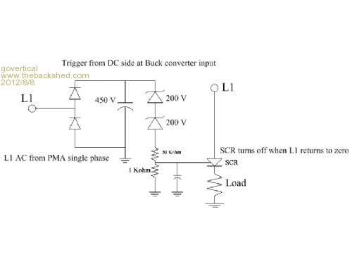
Hi, I order the parts before I understood Steveís circuit. I do not know if the Zeners will breakdown at 400 volts. The trigger signal is from the DC side at the buck converter input. L1 is from the AC side; single phase; from the PMA. If the SCR fires it will reset when L1 returns zero. Load could be a heating element so the PMA stator would stay cool. May be a possible solution for the input over voltage protection circuit. Comments welcome
just because your a GURU or forum administer does not mean your always correct :) |
| |
Warpspeed
Guru

Joined: 09/08/2007
Location: AustraliaPosts: 4406 |
| Posted: 05:06pm 07 Aug 2012 |
 Copy link to clipboard Copy link to clipboard |
 Print this post |
|
I can see a couple of problems with that circuit.
First is that the SCR will only clamp the positive ac half cycles, it will turn off during the negative half cycles.
When turned on an SCR behaves more or less like an ordinary diode and can only conduct in one direction.
If you want it to clamp both sides of an AC signal, you need to use a Triac not an SCR.
And the load should be connected between L1 and the SCR, not where it is drawn, between the SCR and ground.
Cheers, †Tony. |
| |
govertical
Guru

Joined: 11/12/2008
Location: United StatesPosts: 383 |
| Posted: 12:23pm 11 Aug 2012 |
 Copy link to clipboard Copy link to clipboard |
 Print this post |
|
just because your a GURU or forum administer does not mean your always correct :) |
| |
Warpspeed
Guru

Joined: 09/08/2007
Location: AustraliaPosts: 4406 |
| Posted: 01:19pm 11 Aug 2012 |
 Copy link to clipboard Copy link to clipboard |
 Print this post |
|
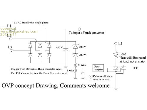
You cannot connect two SCRs like that. And the resistive load will load up only one phase on one half cycle only, which will not do very much.
Your best bet would be to revert to one single SCR (as original) and connect the top end of the resistive load direct to the +ve dc output of the bridge rectifier.
The SCR will turn on, and place the resistive load directly across the output of the bridge rectifier. That will load all three phases on both halves of the cycle.
The SCR will then keep conducting until wind speed drops back to zero.
One way to turn off the SCR would be to place a switch or a normally closed push button in series with the dc load resistor.
Cheers, †Tony. |
| |
govertical
Guru

Joined: 11/12/2008
Location: United StatesPosts: 383 |
| Posted: 09:13am 12 Aug 2012 |
 Copy link to clipboard Copy link to clipboard |
 Print this post |
|
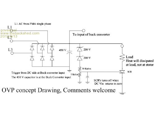
Hi, I am searching for a over voltage protection circuit for the input of the buck converter. Before I can add a micro I need the buck converter to have a rock solid operation for all wind conditions. All PMAís are not the same, so I am trying to design the buck converter for maximum values using the parts that I have available. When the duty cycle of the buck converter is small ;less than 10 %; the input voltage can exceed the maximum value of the mosfet and it will be damaged. I have finally ordered a book on power electronics to search for a solution. I have no experience with power electronics.
L1, L2, and L3 are the outputs of the 3 phase star PMA. The max voltage value of the mosfet is 500 volts. I am searching for a OVP circuit or chopper circuit that will trigger at 400 volts.
just because your a GURU or forum administer does not mean your always correct :) |
| |
Warpspeed
Guru

Joined: 09/08/2007
Location: AustraliaPosts: 4406 |
| Posted: 12:59pm 12 Aug 2012 |
 Copy link to clipboard Copy link to clipboard |
 Print this post |
|
Your first circuit was 99% there.
Ground the bottom (cathode) of the SCR.
Put the load resistor between the top (anode) of the SCR and the dc output of the rectifier.

Cheers, †Tony. |
| |
govertical
Guru

Joined: 11/12/2008
Location: United StatesPosts: 383 |
| Posted: 02:17pm 12 Aug 2012 |
 Copy link to clipboard Copy link to clipboard |
 Print this post |
|
Hi, update drawing. I have parts to test this idea. I will post results when available. Thanks for the help.
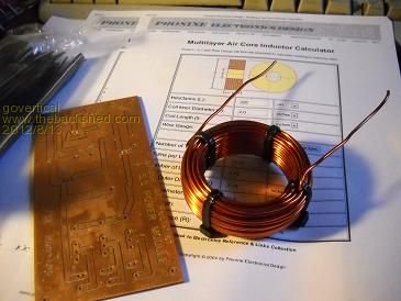
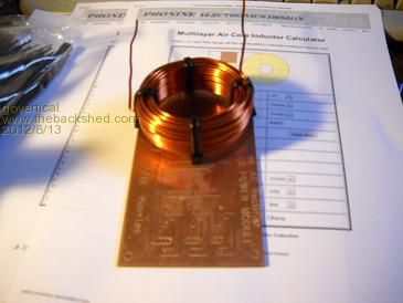
The Toroids I purchased are over heating. I was getting better results using the air core inductors. The only place I can mount them is on the bottom side of the PCB.
Edited by govertical 2012-08-14
just because your a GURU or forum administer does not mean your always correct :) |
| |
Warpspeed
Guru

Joined: 09/08/2007
Location: AustraliaPosts: 4406 |
| Posted: 02:39pm 12 Aug 2012 |
 Copy link to clipboard Copy link to clipboard |
 Print this post |
|
That should work fine.
At >400v the SCR will latch permanently on, and the load resistor can be arranged to pull just enough power to keep the voltage in a safe range.
Something like an electric radiator element would probably do it.

For some reason I can no longer upload pictures to Photobucket, so am unable to create circuit diagrams that I can post on the Forum.
Cheers, †Tony. |
| |
govertical
Guru

Joined: 11/12/2008
Location: United StatesPosts: 383 |
| Posted: 04:04pm 12 Aug 2012 |
 Copy link to clipboard Copy link to clipboard |
 Print this post |
|
Hi, just send them to me attached to a email and will post them for you 
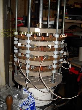
I just tested the 4 stator PMA and measure 8 amps DC using just 2 buck converter. I broke the other two. The inductor measured around 100 degrees F. Input voltage was 51 volts DC with about 1.7amps DC. Output was 8 amps DC at 15 volts DC. I have to buy better meters. But this the best I have been able to measure using the Drill press test fixture. This does indicate I am heading in the correct direction. Measured rotor RPM was 360. If I use the 1 to 7 belt drive I should be able to get usable power at a lower wind speed when I increase the blade size. Buck converter duty cycle was 50%
just because your a GURU or forum administer does not mean your always correct :) |
| |
herbnz

Senior Member

Joined: 18/02/2007
Location: New ZealandPosts: 258 |
| Posted: 07:19pm 12 Aug 2012 |
 Copy link to clipboard Copy link to clipboard |
 Print this post |
|
Hi
Adding a second SCR (small) and Capacitor can give a means of reseting with a pulse more details on anotherpower.
HerbEdited by herbnz 2012-08-14 |
| |
govertical
Guru

Joined: 11/12/2008
Location: United StatesPosts: 383 |
| Posted: 12:51am 21 Aug 2012 |
 Copy link to clipboard Copy link to clipboard |
 Print this post |
|
Hi, output voltage of the F&P stock coil configuration is so high it creates a problem when used with a buck converter. The high output voltage requires the duty cycle to be very small. Other projects using the F&P have reconfigured the coils to produce a lower voltage with higher current output.
Making sure that the correct wire is cut is very important and confusing. It is going to take some time.
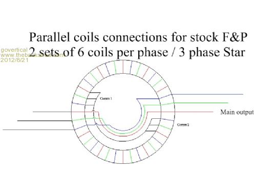
To use the F&P with 36 coils one possible solution is to connect the coils to form 2 sets of 6 coils per phase in a 3 phase star configuration. Then the two sets can be connected in parallel.
Concept drawing is a attempt to show connection pattern, but it is confusing.
Still working on OVP circuit, thanks for the info.
just because your a GURU or forum administer does not mean your always correct :) |
| |
Warpspeed
Guru

Joined: 09/08/2007
Location: AustraliaPosts: 4406 |
| Posted: 12:15pm 21 Aug 2012 |
 Copy link to clipboard Copy link to clipboard |
 Print this post |
|
One very simple way to reduce the voltage is to just split the original star junction point.
That then gives you three completely separate individual windings (with six wires total).
Connect each winding to it's own four diode bridge rectifier.
Parallel the three bridge rectifiers at the dc outputs.
That will reduce the original dc output voltage by 1.73 times, or down to a bit more than half of what it was originally.
This should be fairly simple and straightforward to do with very little chance of getting things wrong.
And you don't need to worry about the phasing of the windings going to the rectifiers.
If you need a bigger reduction than 1.73, then further segregation of windings will be required.
While the individual rectifier method of connection is theoretically very slightly less efficient than star connection, it does allow a greater combination of possible connections, and output voltage possibilities.
Cheers, †Tony. |
| |
govertical
Guru

Joined: 11/12/2008
Location: United StatesPosts: 383 |
| Posted: 03:14pm 22 Aug 2012 |
 Copy link to clipboard Copy link to clipboard |
 Print this post |
|
Hi, I completed F&P modification. It is now two 6 coil/phase 3 phase star connected in parallel. Replaced the spade connecters with screw terminals. Output to output resistance is about 10 ohms.
I started the modifications before I seen your suggestions.
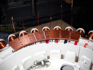
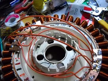
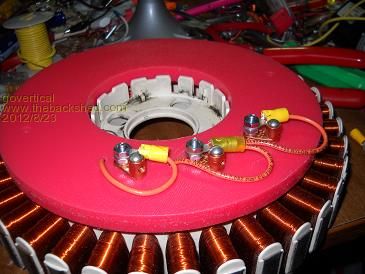
The end caps covers the wire mess.
just because your a GURU or forum administer does not mean your always correct :) |
| |
govertical
Guru

Joined: 11/12/2008
Location: United StatesPosts: 383 |
| Posted: 05:15pm 23 Aug 2012 |
 Copy link to clipboard Copy link to clipboard |
 Print this post |
|
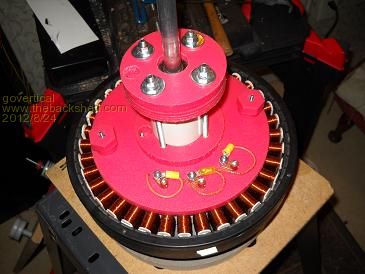
Hi, photo of completed assembly after modification.
just because your a GURU or forum administer does not mean your always correct :) |
| |
| |
  Page 3 of 6 Page 3 of 6   |

