
|

|
Forum Index : Windmills : A small HAWT
| Author | Message | ||||
| Tinker Guru Joined: 07/11/2007 Location: AustraliaPosts: 1904 |
Dean, I thought you might want to solder connect the brushes. Just be very careful how you do it - that fine wire acts like solder wick and you can have the whole pigtail solid in no time. I suggest you use a big soldering iron, ~80W, and hold the brushes in a clamp so that the tails hang down. Do the soldering as quick as possible. You might have known the above already but then maybe not  . .
The pro's spot weld the brush tails to a lug for connection. If this was my slip ring I would use those brass 2 screw connectors as found in mains electrical connectors instead of soldering. Klaus |
||||
| Air Bender Senior Member Joined: 25/01/2011 Location: AustraliaPosts: 206 |
Thanks Klaus and Rastus, While looking at the above picture I think I should try and cut some holes in the lid of the container and fit it onto the bottom. it has 4 clips around it and has a rubber seal. I think when I get rain with wind the blades will chop the rain up into mist and the mist will waft up inside the container. All the best Dean. |
||||
| Rastus Guru Joined: 29/10/2010 Location: AustraliaPosts: 301 |
Hi Dean, Capillary action of water is fasinating.It can be drawn uphill with no apparent force,so waterproofing is a must.Cheers Rastus see Rastus graduate advise generously |
||||
| paceman Guru Joined: 07/10/2011 Location: AustraliaPosts: 1329 |
Hi Dean, Further on connecting the pigtails. If you can borrow a swaging tool that might be the way to go - no soldering. They're similar to car type wiring connectors but bigger (different sizes are available) stronger and make better contact. You'd also be able to stuff all the braid in easily. The connectors themselves are available in copper too. Commonly used by yachties and also for those stainless steel wire balcony "rails". Greg |
||||
| Air Bender Senior Member Joined: 25/01/2011 Location: AustraliaPosts: 206 |
Hi all. I have some crimp on terminal lugs at home, I might need to open up the bit that crimps around the wire a bit to fit the pig tails in. Im not bad at soldering I thing the trick is to apply the heat to where you want the solder to run and like Klaus said do it quickly as the more area that is heated up the more chance there of solder running where you dont want it to go. I think I will need to remake my cover, now that I am going to put the lid on the bottom of the cover, the lid is what I should have the brackets conected to, and then the cover can be held in place by clips on the lid. I have drilled holes in the cover now so I will go up to the supermarket and buy a new one, they only cost a couple of dollars. My days of have been cut short, I was called back into work yesterday but I do have access to the internet on the computer in the boilerhouse which is were I am at the moment I am limited to what I can do on it but it does allow me to post on the back shed. All the Best Dean. |
||||
| Air Bender Senior Member Joined: 25/01/2011 Location: AustraliaPosts: 206 |
Hi all, My second attempt at a cover was abandoned after I fitted the blade hub the chain was rubbing on it  , But my third attempt has worked. It has been harder to fit a cover than making the slip rings.I have added some brass terminal bolts to the brush arms but that is about as far as I have got. We are a couple of guys down at work so all I have been doing is working sleeping and going back to work again , But my third attempt has worked. It has been harder to fit a cover than making the slip rings.I have added some brass terminal bolts to the brush arms but that is about as far as I have got. We are a couple of guys down at work so all I have been doing is working sleeping and going back to work again
All the best Dean. |
||||
| Air Bender Senior Member Joined: 25/01/2011 Location: AustraliaPosts: 206 |
Hi all, Slip rings and cover are finnished, and new bearing cups have been fitted. Bike cranks tend to wear uneven, the old bearings had a slight wobble. Any movment in the shaft causes the chain to go slack and then tight as it rotates. 14 dollars spent on the new bearing set will be well worth it at the end of the day saving on chain wear and bearing wear in the DC motor. 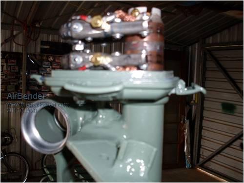
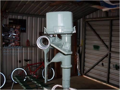
I have just got a bit more painting to do and a final asembly and then I need to look at getting a pole. I am looking at a 7m pole that will put the hub level with the top of the vawt wings. Pole wire and cable will be the most expensive part of the build. All the best Dean. |
||||
| Air Bender Senior Member Joined: 25/01/2011 Location: AustraliaPosts: 206 |
Hi all, The wind mill was full assembled this afternoon and is ready to go up when I get a pole. The hub runs very true with the new bearings and the chain runs smoother than it did on my last test. the blades were only roughly shaped up and wernt balanced on the last test so I might get a bit of improvment on performance when it goes up. 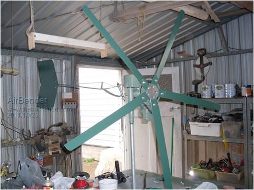
All the best Dean. |
||||
| Gizmo Admin Group Joined: 05/06/2004 Location: AustraliaPosts: 5078 |
I bet your keen to see it fly. 
Nice work. Glenn The best time to plant a tree was twenty years ago, the second best time is right now. JAQ |
||||
| Air Bender Senior Member Joined: 25/01/2011 Location: AustraliaPosts: 206 |
Thanks Glen, I will need to another amp meter and a diode to wire this in. It is the diode I am not sure about, what type and size is best to use, electronics is not one of my stronger areas. I do have a 35 amp bridge rectifier I was wondering if I could use one side of it or is there a better option out there All the best Dean. |
||||
| daveames Newbie Joined: 19/09/2009 Location: United StatesPosts: 30 |
Hey Dean, Some nice bits of fabrication there! Looking forward to seeing her fly 
Had some luck with using a standard bridge for our blocking diode while running a PMDC motor. Seems to work well when we tag both AC inputs of the bridge with the positive output lead of the motor.. then take our "plus sign" output out of the bridge to the battery bank. ...this diagram shows a fuse, if we go that route we want to go BIG with the fuse..IE we never want the mill to be able to trip it and want the fuse only to protect the wires in a case of some kind of battery short. 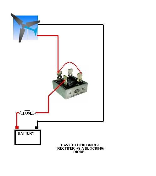
Looking good. Cheers, dave 73 De KB1MZF |
||||
| Air Bender Senior Member Joined: 25/01/2011 Location: AustraliaPosts: 206 |
Thanks Dave, That is a very easy to read diagram and the bridge rectifier I have is identical. My son has finaly brought home an anometer he made a while back, it has been in the science room at his school for the last 6 months his teacher was very impressed, so not only do I need to get a pole up for the mill but we will get the anometer up as well. It will be good to be able to note output to wind speed. All the best Dean. |
||||
| Air Bender Senior Member Joined: 25/01/2011 Location: AustraliaPosts: 206 |
Hi all, The pole is up and I lifted the mill up for a test today. I still dont have a wires running down the pole yet but it spun up very fast in 15-20 km/h winds. I am looking forward to wiring it in so I can see what kind of power it is puting out. 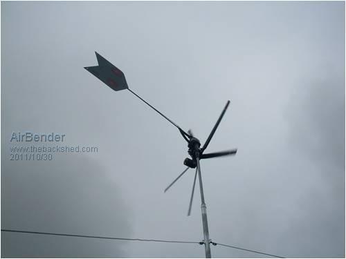
There are a few different 24v dc motors out there that I might test down the track when I get my hands on them, as I beleive I am getting high enough rpm to run most of these motors. All the best Dean. |
||||
| Air Bender Senior Member Joined: 25/01/2011 Location: AustraliaPosts: 206 |
Hi all, The mill is back in the shed untill I get some wiring in place. Later this afternoon we got some stronger gusts come through at over 20km/h, the mill was screaming with no load on the alt, the tail started moving in of its stop a bit, so I may have this set up close but I wont know untill I get a load on the alt to see if it is furling to early, but if so I might try adding a bit of weight to the tail. A good day of testing done today All the best Dean. |
||||
| Air Bender Senior Member Joined: 25/01/2011 Location: AustraliaPosts: 206 |
Hi all Pictures of the tilt tower set up. 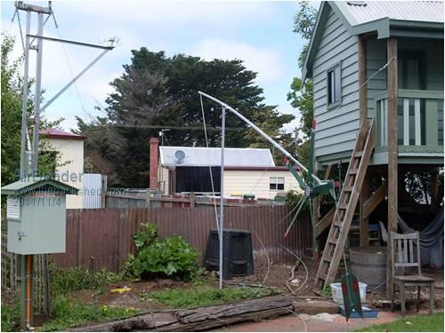
Pole is a bit bendy when tilted down but it is very easy to tilt up and down by disconecting one guy wire and two wing nuts that clamp the two poles together at the bottom and then I lower it down by the chain. The pole is 6m long. 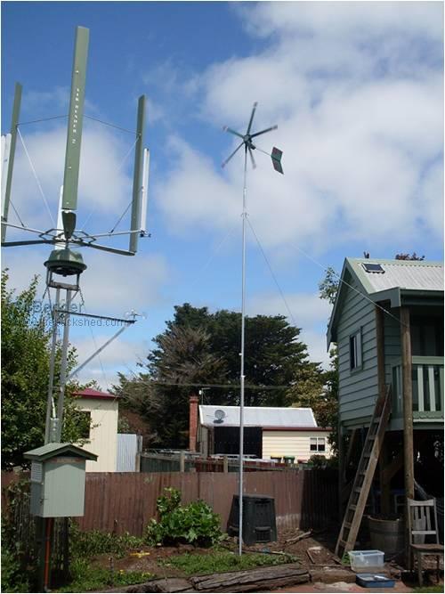
The two mills together. Still no wiring on the small hawt yet. Very light winds today and both mills started spinning at the same time in 5 km/h of wind and I am quesing the the hawt will reach cut in about the same time as the Vawt which is at 10 km/h. so now I will take the hawt back down and go and try and chase up some wire. All the best Dean. |
||||
| Air Bender Senior Member Joined: 25/01/2011 Location: AustraliaPosts: 206 |
Hi all, I finaly have some wiring down the pole and I have it connected to an old car battery and have started testing the output. In about 20 kl/ph winds it is making 2 amps feeding into a 12volt battery. The motor I am using if memory serves me correct as there is no markings left on it is 24V DC 100w at 3600 rpm. I have had the calculator out and I worked out to make 14 V the motor is turning at 2118 rpm and with the gearing of 2.5/1 the blades are spinning at 847rpm. The mill is reaching this cut in speed but only just in above average wind speeds, not ideal, I have just ordered a 24V DC 300w at 2750rpm motor, which I worked out should make 14v at 1618rpm motor speed and 647rpm blade speed. This should drop my cut in blade speed down by 200rpms. I dont know if all my calculating will turn out correct but if it does the new motor should reach cut in at 14v at about the same time that the current motor is putting out 10-11V which is where this mill is running at most of the time and hopfully push out some more amps. The new motor has nearly twice the diameter as the old one but the length is about the same which should make it an easy transplant at the mountings. All the best Dean. |
||||
| Tinker Guru Joined: 07/11/2007 Location: AustraliaPosts: 1904 |
Dean, this would have me worried, something with blades spinning at 647RPM above my head. Are you sure you got that info right, its seriously fast RPM for anything larger than 0.5m diameter. Klaus |
||||
| Air Bender Senior Member Joined: 25/01/2011 Location: AustraliaPosts: 206 |
Hi Klaus, These calculations are only taken by the ratings on the motors. unfortunatly I dont have a output curve for these motors. The motor I am using at the moment came of a E100 scooter and after looking around on the net I found all these motors are rated at 3600 RPM at 24V. These blades are spinning at very high speed which is a bit of a worry but also when they start to put out over 12v the blades start to produce a high pitched whistle not much louder than chain and bearing noise but it could become anoying over time. Another option I have is to increase the gearing as it is starting to spin in light winds a long time before it reaches cut in, so a bit more load on the gearing would bring this a bit closer together. But I will try a different motor first. They are forcasting winds stronger today which will be interesting. All the best Dean. |
||||
MrDelanco Senior Member Joined: 12/11/2011 Location: United StatesPosts: 101 |
Very nice work. Hope it works well for you. Regards Bob. MrDelanco:Project Videos It is not only too know what it does but to understand how it does what it does. |
||||
| Tinker Guru Joined: 07/11/2007 Location: AustraliaPosts: 1904 |
So you are planning to use a PM motor with brushes, and a high RPM one at that, to generate electricity? While it will work I don't think its a long term solution past the experimenting stage. Any noise, whistling, whining, whirring ..., would attract unwanted attention to it and I would not want it in my back yard nor on the other side of the fence  . .
Which is why so many here experiment with the F&P motor. It can easily be rewired to cut in at a much lower RPM for a 24V system than your scooter motor. And it puts out AC which is easy to rectify at the battery end of the cable. You could get F&P motors for next to nothing from the recycling center. Its rarely the motor itself that caused the owner to dump the washing machine, the two I took apart - on was very old - had control board problems and one had a bearing on its way out. I do use gearing (6.4 : 1 planetary) on that Lenz II I'm messing about with but its completely silent as it spins at low RPM. I'm aiming to extract power from high torque rather from high RPM when I finally get this thing's performance up to my expectation  . .Klaus |
||||