|

|
Forum Index : Microcontroller and PC projects : World’s first COLOUR Maximite!!
| Author | Message | ||||
| sparkey Senior Member Joined: 15/06/2011 Location: AustraliaPosts: 819 |
well done nick you and stu have put a lot of work and been throwing round ideas your both assettes to the cause in my op technicians do it with least resistance |
||||
VK6MRG Guru Joined: 08/06/2011 Location: AustraliaPosts: 347 |
I'll take 2 
Oh, and a copy of space invaders  Its easier to ask forgiveness than to seek permission! ............VK6MRG.............VK3MGR............ |
||||
| Nick Guru Joined: 09/06/2011 Location: AustraliaPosts: 512 |
Regarding the not-so-black black... Unplugged the colour mod and ran the MM normally through my LCD screen and still found that the background black is too lit up. It looks more like a grey than a black. Tried 2 x other LCD monitors with the same results. I then pulled out my VGA CRT monitor and the image was, as I expected, BEAUTIFUL! Blacks were black and text reproduction was crystal clear and sharp. Bloody LCD monitors!! Is there something on the MM that could be done to get better blacks on the LCD? NOTE: The LCD monitors I tried are of the fluorescent backlight variety (not LED). But connecting them to a PC doesn't have as 'gray' a background. ALSO: My MM often fails to power up correctly. Sometimes I have to try multiple on/off transitions of the power switch before it will start. When it does, it works fine. It does this with any monitor, LCD or CRT so it's not monitor related. I suspect it's a power issue and have tried several different power adaptor but the problem persists. |
||||
donmck Guru Joined: 09/06/2011 Location: AustraliaPosts: 1313 |
http://www.thebackshed.com/forum/forum_posts.asp?TID=3550&PN =1&TPN=2 may give you some leads on the power up problem Nick, Cheers Don... https://www.dontronics.com |
||||
James_From_Canb Senior Member Joined: 19/06/2011 Location: AustraliaPosts: 265 |
Didn't Geoff mention that the Grey background was because of the way it was implemented? James My mind is aglow with whirling, transient nodes of thought careening through a cosmic vapor of invention. Hedley Lamarr, Blazing Saddles (1974) |
||||
| Nick Guru Joined: 09/06/2011 Location: AustraliaPosts: 512 |
By golly! I think that it is. I'll try it tonight. Thanks Don and Stuart. 
Ah.. More answers. So I may have been banging my head against the wall for nothing? What concerns me most is that I felt no pain whatsover! Even started to enjoy it!  |
||||
James_From_Canb Senior Member Joined: 19/06/2011 Location: AustraliaPosts: 265 |
Found it. Silicon Chip, Mar 2011, page 37, second para onwards: "At the top right hand section of the diagram is the video output. The components and values shown in fig 1 are chosen to allow you to switch between VGA and composite video output. This involves some compromises; in the case of VGA the black level is not truly black and for composite the white level is not as bright as it could be. However the resulting video is perfectly acceptable and can be corrected by adjusting the monitor to suit. If you want a perfect picture all the time you can permanently configure the video for either of the standards as shown in fig 2a and 2b." The article then goes into how the video circuitry works. Have you considered wielding the soldering iron and setting up your Maximite purely for VGA (or composite) and see how it goes? My mind is aglow with whirling, transient nodes of thought careening through a cosmic vapor of invention. Hedley Lamarr, Blazing Saddles (1974) |
||||
| sparkey Senior Member Joined: 15/06/2011 Location: AustraliaPosts: 819 |
turn your video levels down.....on your screen try running a plasma and you will see the difference as "l.c.d`s" dont have a true black technicians do it with least resistance |
||||
| terrapinlogo Newbie Joined: 26/10/2009 Location: New ZealandPosts: 21 |
Just built this using a LTC201A from Linear (it was a sample so I'd better mention them) and it is working well. A great mod!! I had some trouble at first with the background being a light shade of the colour selected with the text being a brighter shade of the same colour. Worked out that it was because I had the Maximite setup to be used in both video modes but once I lifted the 680r resistor the background was black like expected. I have supplied power to the chip from pin 9 of the VGA connector with a wire soldered to the bottom of the maximite board. Means you only have to hook up the 3 colour signals. The best part is that from what I have found it is in spec with the VGA standards too so it doesn't need to be removed to use the Maximite without the mod. If it doesn't work hit it with a bigger hammer. If it still doesn't work you probably shouldn't of hit it. |
||||
| Nick Guru Joined: 09/06/2011 Location: AustraliaPosts: 512 |
Good work terrapinlogo! Any chance of an updated schematic with your changes? This idea was a very low cost way of providing colour to the maximite as a simple plug in accessory... no changes or mods to the existing hardware. To achieve it's full potential, it would require a rewrite of the MMBASIC firmware video driver so that a "colour table" could be defined that tells the video driver firmware what colour to select at each horizontal scanline of video. This would allow 8 simultaneous colours on screen. A further enhancement to the hardware would be to include an "intensity" bit that could double the colour range to 16 colours like the old 16 colour VGA (RGBi). Nick |
||||
| terrapinlogo Newbie Joined: 26/10/2009 Location: New ZealandPosts: 21 |
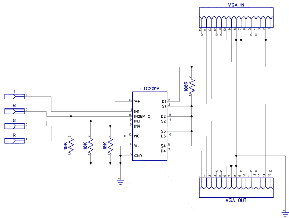
Heres the schematic: 
The 100R resistor for I is about right and makes the colours about half as bright as they normally are. The mod to the bottom of the maximite board. The actual device. The white taped bit at the top is the sync lines and a ground line to stop the screen from flickering. and working. The colour is actually purple, the camera made it look blue for some reason. If it doesn't work hit it with a bigger hammer. If it still doesn't work you probably shouldn't of hit it. |
||||
| Nick Guru Joined: 09/06/2011 Location: AustraliaPosts: 512 |
Cool! Unfortunately, my circuit has been dismantled so I should try and get one of the chips that you used and rebuild it. Here's an experiment to try... This ideally should be done at the Machine Code level but I wonder if MMBASIC is fast enough to change the colour in such a way to get a moving rainbow effect on the screen. Better still, if it can be syncronised somehow to an interrupt so the colour change occurs at a consistent time. This is merely to test the theory that the circuit would be fast enough to change the colour at a scanline level. The chip used may not be fast enough. Nick |
||||
| ebjoew Newbie Joined: 15/07/2012 Location: United StatesPosts: 4 |
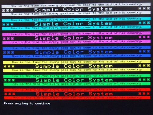
I am new here. This is my first post. Sometimes, coincidences are just too hard to believe. I bought a CGMMSTICK1 board about two weeks ago as my introduction to MMBASIC and MaxiMite-like computers. It is all new to me. After cutting a keyboard connector and VGA connector off an old dead PC motherboard and wiring them into my breadboard setup, I began to think about a simple way to add some color to the video display when using VGA. It works fairly closely to what Nick is describing. Although I do not control the color timing quite down to the scan line level, I do control it closely enough to make a color video display that is stable and solid and did it all just using some passive parts (no ICs, no transistors) and standard MMBASIC 3.2C without any firmware mods at all. I even worked in some blink effects. Only then did I discover this topic on The Back Shed. Too Strange. I am sure this could be done externally using a MaxiMite and many of the other similar machines. If there is interest, I will be glad to supply details about how I did it. Please excuse my image being slightly tilted. I did not have the camera lined up with the monitor very well. 
Joe |
||||
bigmik Guru Joined: 20/06/2011 Location: AustraliaPosts: 2914 |
I am interested please provide the technical details. Mick Mick's uMite Stuff can be found >>> HERE (Kindly hosted by Dontronics) <<< |
||||
| terrapinlogo Newbie Joined: 26/10/2009 Location: New ZealandPosts: 21 |
Yep definately keen for more detail If it doesn't work hit it with a bigger hammer. If it still doesn't work you probably shouldn't of hit it. |
||||
| ebjoew Newbie Joined: 15/07/2012 Location: United StatesPosts: 4 |
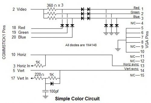
A Simple Color System For The CGMMSTICK1 Computer Part 1 - Hardware I determined that the Video2 signal on pin 3 of the CGMMSTICK1 is actually an input and would be better labelled Horiz In. So in my circuit shown below, you will see that label appearing on that signal instead of Video2. 
When I fed the Vert sync signal back in so that an interrupt could be generated from it, the resulting interrupts were somewhat intermittent. I played with a few things and found that it became much more reliable if the Vert In signal stays low a little longer so I endeavored to stretch it. That is the function of the 1K resistor, the 100 picofarad capacitor, and the diode in that circuit. Part 2 - Software There are two main elements to the software. One is the interrupt routine that services the Vert In interrupt. The other is a single Subprogram called SC. SC may be called from a program to initiate or stop the coloring of the screen. It operates independently of the actual printing on the screen. Therefore, it is possible to establish a set of color bands on the screen and then print text or draw graphic images on the screen. It is also possible to create the text and/or graphics first and then establish the color bands using SC. SC takes a single argument, a character string. If the string is empty it shuts down all coloring of the screen and discontinues the processing of the Vert In interrupts. If the character string argument to SC is not empty, it is expected to contain one or more color bar descriptors. If there are more than one, they should be separated by commas. The color bars must be specified starting at the top of the screen and working the way down. A color bar descriptor consists of three digits, a space, and one or two color codes. Permitted color codes include: BLK - Black RED - Red GRN - Green YEL - Yellow BLU - Blue MAG - Magenta CYN - Cyan WHT - White While the color codes are shown in upper case here, they are not case sensitive so "mag" is the same as "MAG" or "Mag". The 3-digit number that precedes the color code describes how tall the color band is on the screen. The shortest band possible (indicated with "001") results in a color band about 16 scan lines high. The greater the number, the taller will be the color band. "999" is nearly as high as the entire screen. A value of "000" has special meaning which I will cover in a bit. During testing, I have managed to put as many as 26 color bars down the screen. Remember that what we are doing is coloring the video that would otherwise be white if the color system were not in use. Therefore, whereas text is usually white characters on a black background, when appearing in a color bar, the characters are that color on a black background. Reversed text is normally presented as black characters on a white background, so it appears as black characters on a colored background when in a color bar. It looks rather strange when the boundary between two color bars passes through some text. The upper part of each character is one color and the lower part is a different color. To make matters worse, the response of the Vert In interrupt varies a little bit causing all the color bars on the screen to be slightly unstable and move up and down randomly about one or two scan lines. The best remedy that I have found for this is to leave a blank space in the graphics on the screen where the color bars meet. The descriptor for the lowest color bar on the screen can just use a height value of 000. SC will know this means it must be the last color bar. The color bar specified will simply apply for the rest of the screen. There is another feature in this little system that yields blinking text or graphics. A color descriptor may specify one color code or it may specify two. When two color codes appear, a slash (/) must separate them. The color bar being described will alternate in color between the two colors specified. An example of using this might be to present a prompt to an operator within a color bar specified as WHT/BLK. This will mean that the prompt will be blinking off and on and will be white when it is present. It might also be specified as WHT/RED and then it would alternate between white and red characters. If one color bar is specified with two colors such as WHT/RED and another is specified with RED/WHT, they will be seen to alternate colors in opposite phase to each other. The blink rate is determined by the number 20 that appears in a line in the interrupt service procedure. Replacing the 20 with smaller numbers increases the blinking rate. Although I used pins 17 through 20 for my color system, any 4 I/O pins could probably be used. The pin numbers for the pins used are assigned in the first line of the SC sub procedure. I stayed with the 5-volt tolerant pins to be safe. I suspect that the Red, Green, and Blue signals could be assigned to pins in the non-5-volt tolerant group because I suspect the Video signal is a 3.3 volt output but I cannot be sure. Trying any of these pins would be at your own risk. Actually, doing any of this to your equipment is at your own risk. I am just showing you what I managed to make work on my machine. Here follows the demo program I wrote to test this. I would not be surprised if some of the magic numbers would need to be tweaked when other versions of MMBasic are used and perhaps even when this is used with many more variables and additional program code, etc. I hope you find this useful, Joe 'Demo of the Simple Color system for CGMMSTICK1 'Author: Joe Watson Date: 15-Jul-2012 Cls NowIs$="Now is the time for every good man to come to the aid of his country." For i=1 To 7 Font 1,1,1:Print " ";NowIs$;" " Font 2,1,0:Print "*** Simple Color System ***" Font 1,1,1:Print " ";NowIs$;" " Next Font 1,1,0:Print "Press any key to continue"; 'Set the color bands SC "097 Wht,097 Cyn,097 Mag,097 Blu,097 Yel,097 Grn,097 Red,000 Wht/Grn" Do:Loop Until Inkey$>"" 'Wait for the operator to press a key SC "" 'Turn off the color system End Sub SC(A$) 'Simple Color If VPin=0 Then VPin=17:RPin=18:GPin=19:BPin=20:Dim SCL(36,3),Z,Z1,Z2,Z4,J,Tm SCN=0:Local I,Col$,S$,Cma,Strt,Cols$:Cols$=",,,BLK,RED,GRN,YEL,BLU,MAG,C YN,WHT" If A$="" Then SetPin RPin,0:SetPin GPin,0:SetPin BPin,0:SetPin VPin,0:Exit Sub Do Strt=Cma+1:Cma=Instr(Strt,A$+",",","):S$=Mid$(A$,Strt,Cma-St rt+1) Col$=UCase$(Mid$(S$,5,3)):ColN=(Instr(Cols$,Col$)-4)/4 If ColN<0 Then Pin(GrnPin)=1:Cls:Print "Bad color code:[";Col$;"]":End I=I+1:SCL(I,1)=Val(Left$(S$,3)):SCL(I,2)=ColN:SCL(I,3)=ColN If Mid$(S$,8,1)="/" Then Col$=UCase$(Mid$(S$,9,3)):ColN=(Instr(Cols$,Col$)-4)/4 If ColN<0 Then Pin(GrnPin)=1:Cls:Print "Bad color code:[";Col$;"]":End SCL(I,3)=ColN EndIf Loop Until Cma>=Len(A$) Or SCL(I,1)=0 SetPin RPin,8:SetPin GPin,8:SetPin BPin,8:SetPin VPin,7,SCInt SCN=I End Sub SCInt: Pin(RPin)=1:Pin(GPin)=1:Pin(BPin)=1 'Start with white For Tm=1 To 60:Next 'Delay from vert sync til top of frame SCBlnk=SCBlnk+1:If SCBlnk>=20 Then SCBlnk=-SCBlnk If SCN>0 Then For J=1 To SCN Z=SCL(J,2+(SCBlnk<0)):Z1=Z And 1:Z2=Z And 2:Z4=Z And 4 Pin(RPin)=Z1:Pin(GPin)=Z2:Pin(BPin)=Z4 For Tm=1 To SCL(J,1):Next Next EndIf:IReturn |
||||
| Nick Guru Joined: 09/06/2011 Location: AustraliaPosts: 512 |
Good work ebjoew! I love seeing these little simple projects which achieve something great out of so little. Thanks for the detailed description. Now to find some time to build it up. The new Maximite 2 will have color but this is an easy design to experiment with some colour capability to existing maximites and compatibles. |
||||
| ebjoew Newbie Joined: 15/07/2012 Location: United StatesPosts: 4 |
I suppose that I should also point out that if one codes BLK anywhere in the color descriptors, one risks the possibility of stopping the program (with CTRL/C for example) with what you type being invisible. For that reason, I tend to stay away from BLK most of the time. Even if you do end up in the "dark", entering an EDIT command recovers pretty nicely as all the I/O ports are apparently returned to their inactive states upon entry to the editor. Therefore, the video returns to white automatically. Joe |
||||