| |
  Page 3 of 9 Page 3 of 9   |
| Author |
Message |
VK4AYQ
Guru

Joined: 02/12/2009
Location: AustraliaPosts: 2539 |
| Posted: 09:48pm 19 Nov 2010 |
 Copy link to clipboard Copy link to clipboard |
 Print this post |
|
Hi Phill
I do want to try smaller blades but When I save a few more dollars I will Purchase another mill from you rather than just change the blades on this one as I am very happy how they are starting and putting some energy into the GTI at low wind speeds. I have several other things I want to try as well so do't want to play with this one. I will go through the rest of the work over the next few days to show you what I did.
Not enough wind to get into the furling side of things yet, so as the monkey said that remains to be seen.
All the best
Bob
Foolin Around |
| |
VK4AYQ
Guru

Joined: 02/12/2009
Location: AustraliaPosts: 2539 |
| Posted: 01:49am 22 Nov 2010 |
 Copy link to clipboard Copy link to clipboard |
 Print this post |
|
Hi All
Back to the most critical part of the job, I wanted to fit heavier wire feed out of the alternator, 3mm with silicone high temperature insulation, this required a enlargement of the center hole in the main spindle to allow for the larger wire with thicker insulation.
I wanted to drill the hole out to 10 mm to allow enough room so first step was to use a center drill to start the process, this was because the end of the shaft has a slot in it to allow the wire to be out of the road when using a puller, but it meant an interrupted cut when drilling so making it hard to center the drill and also could lead to the drill grabbing and breaking.
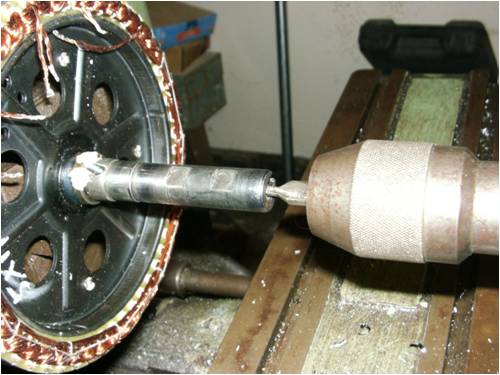
Drilling the hole was a bit of a slow process with plenty of lube on the drill, as you can see it's quite a deep drill, so frequent clearing of cuttings is needed.
This shaft is very strong steel so it was hard going.
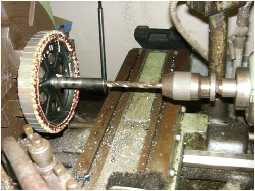
The next photo shows the drill right in and thats where the hole on the shaft for the wires to come out is.
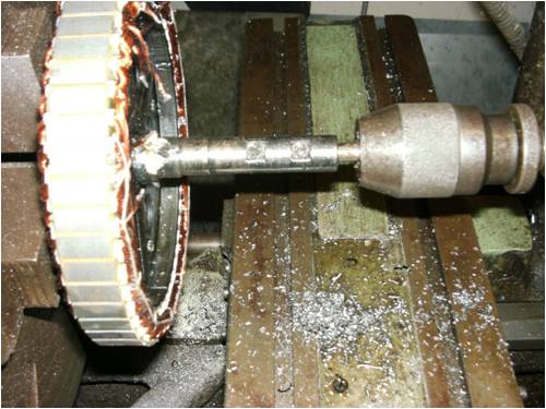
If you don't have access to a lathe it is just as easy to use a drill press to do the drilling, just use a rag or something to prevent the shavings getting into the windings and causing trouble down the track. Still use a center drill to start off the drilling or as Phill suggested you could cut the slot of the end of the shaft as when the bearings are fitted to a slip fit there isn't a need to use a puller for dismantling the alternator, I left mine as is because it gives a little extra shaft in the head socket.
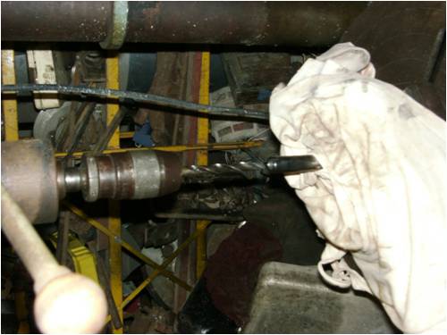
When the drilling is finished there are some sharp edges on the hole that could damage the insulation on the wiring particularly if you are using the silicone wire as the insulation is fragile. I cut the end off a chainsaw file to get the teeth right to the end to do the initial deburring of the hole, the shaft is as hard as the Hobbs of Hell so a bit slow
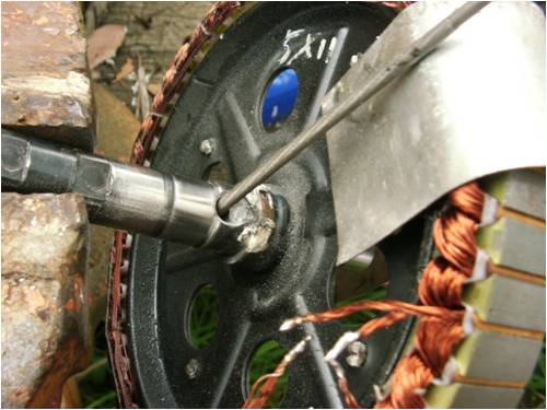
I finished the hole off with a little die grinder using a ball abrasive grit to get right into the hole and smooth the radius of the out feed hole. By doing this all the sharp edges caused by drilling are eliminated and makes fitting the three wires at once a breeze.
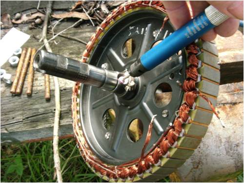
While using the file its a good idea to use a little strip of metal folded over the windings to protect them from Murphies Law.
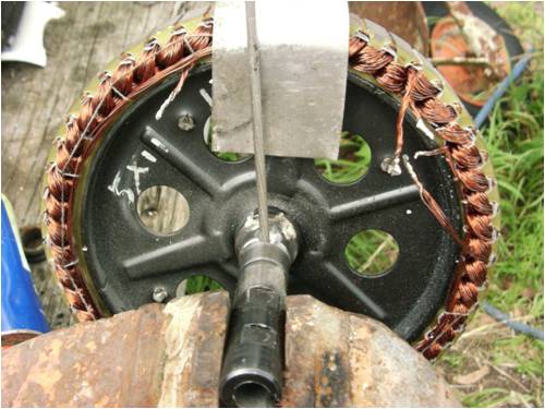
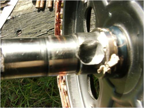
The final polish of the radius-ed hole makes it a lot easier to insert the wires and is well worth the extra effort.
I will compile the photos on the rewiring tonight and post it as time allows.
All the best
Bob
Foolin Around |
| |
GWatPE
Senior Member

Joined: 01/09/2006
Location: AustraliaPosts: 2127 |
| Posted: 12:59pm 22 Nov 2010 |
 Copy link to clipboard Copy link to clipboard |
 Print this post |
|
Hi Bob,
I admire your enthusiasm. As a Devil's advocate, I will ask, by how much has the shaft been hollowed out?
I have seen a windmill of this size break a solid shaft made from a trailer axle.
Gordon.
become more energy aware |
| |
VK4AYQ
Guru

Joined: 02/12/2009
Location: AustraliaPosts: 2539 |
| Posted: 01:49pm 22 Nov 2010 |
 Copy link to clipboard Copy link to clipboard |
 Print this post |
|
Hi Gordon
The shaft has a 10 mm hole in it now it was 8 mm before enlarging, the shaft is very hi tensile but I agree its a bit light on. Next one I will use a bigger shaft and rear bearing because I want to use a 12 mm hole to bring out six wires to try a star delta system.
I think that it would have been OK as original 48 volt star, by just using hi temp 2.5 mm wire through the original hole, as the origination wire was 1.2 mm x 3 and that would have stood up to the 48 volt 1000 watt about 18-20 amps over the three wires on a non continuous basis.
The saving grace of this one is the hole is between the two bearings and at 90 degrees to the furling gyroscopic force. Time will tell as to how it will stand up to the 2.8 meter blades.
Also by smoothing out the hole it should reduce concentrated stresses somewhat.
I will nave it up and down a few times in the next few months so will keep an eye on fatigue, so far the wind has been kind to it as haven't had over 3 ms, but its putting a few watts into the GTI and 5 amps into the batteries on gusts.
All the best
Bob
Foolin Around |
| |
VK4AYQ
Guru

Joined: 02/12/2009
Location: AustraliaPosts: 2539 |
| Posted: 03:02pm 22 Nov 2010 |
 Copy link to clipboard Copy link to clipboard |
 Print this post |
|
Hi All
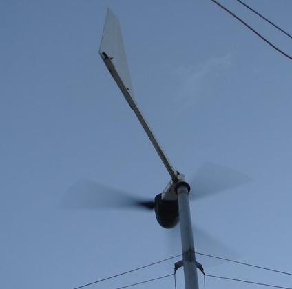
This was the wind today coming from the east through the trees, so potential wind was much higher if no trees in the way.

All the best
Bob
Foolin Around |
| |
VK4AYQ
Guru

Joined: 02/12/2009
Location: AustraliaPosts: 2539 |
| Posted: 11:51pm 23 Nov 2010 |
 Copy link to clipboard Copy link to clipboard |
 Print this post |
|
Hi All
Just a few pics of the wiring, the object of the exercise is to set up a terminal strip on the front of the alternator to make it easier to change from delta to star or visa versa, this can be done by simply removing the front cover / bearing holder for access to the wiring, in the original with the wiring at the back it would be necessary to do a complete dismantle to achieve the same thing.
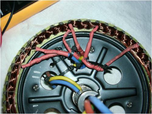
Note that the original star point is opened and all six wires are taken through the existing holes in the stator, all the wires are restrained by zip ties and joints insulated with two layers of heat shrink tubing.
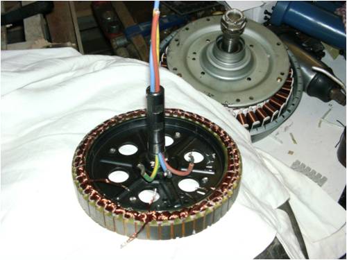
This shows the 3 main wires through the main shaft, they are 3mm and with thick silicone insulation, to get them through the hole I put a heat shrink sleeve on the end being inserted in the hole with a little bit of vasaline to help it slide in.
It is very important to make sure there are no sharp edges on the exit hole, as the silicone is a bit soft and can be damaged easily, found that out by sad experience.
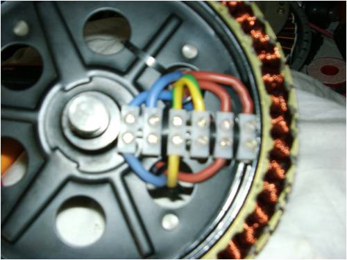
The terminal block was fitted using a bit of contact cement and several zip ties through the existing holes. Note that the six wires 2 from each phase can easily be connected in star or delta by positioning the jumpers.
I am running mine in Delta at the moment with good results from a casual assessment with volt and amp meters on the DC side. More on that later.
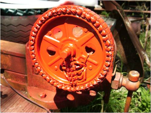
Once the stator was rewired it was given several coats of high temperature enamel to hold the windings a bit firmer as they haven't been varnished in manufacture just string tied into place, it also stuck the general wiring in place a bit, not that is so important as it is the stator.
The winding are five in hand so even though the wire looks thin at first glance the total amount of wire is OK, the unit is based on a 1000 Watt 48 volt wheel motor for a bike, so the original rating indicated around 25 amps in star configuration.
The other purpose was to moisture proof the stator as to improve the ventilation there is a number of holes drilled in the front and back cover to lower the operating temperature of the innards. The original design is a virtual sealed unit with no way for heat to get away from the windings apart from conduction through the main shaft, this has allowed heat build up problems in extreme conditions. While this mod isn't a
ideal fix it is just an experiment to see how it goes, the little alternator is capable of producing more amps than is good for it in its sealed state so we will see how this goes.
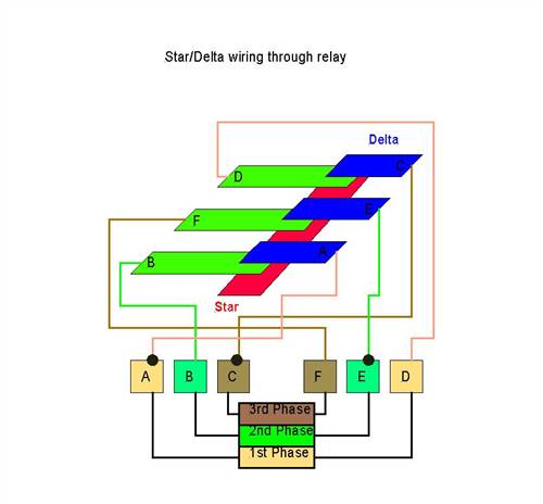
This was the star delta switching I was hoping to use but it would have meant drilling out the center hole to much for comfort, next time I do one I will make a bigger shaft so this can be incorporated, the idea is to let the mill start in star and as the rpm increases above a set point, 250 rpm from lathe testing, then it drops into delta for more efficiency.
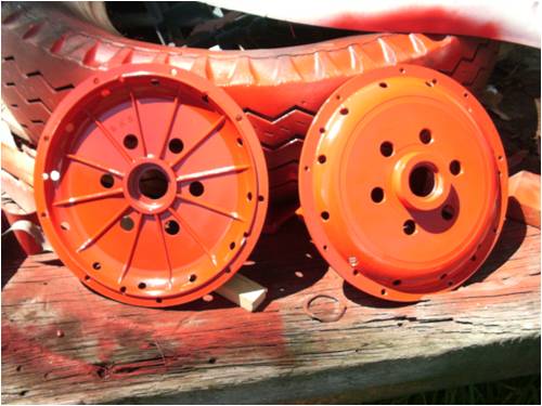
This shows the end caps doing a imitation of red swiss cheese, there are three lots of holes the bigger ones near the center are the inlet 19 mm the outlet holes are on the outer rim to exhaust the air by centrifugal force and on the flange there are holes that act as drains should any water enter the alternator. The whole inside is painted with high temperature enamel to prevent corrosion, I wouldn't recommend this modification to anyone living in a corrosive atmosphere. In that situation it would be better to limit the output by careful furling adjustments, and smaller blades.
Note:
When assembling the alternator I put flat washers under the heads of the Allen screws as it originally had small spring washers that had been forced down the holes in the covers, this didn't allow for proper tightening of the Allen screws. As they are only 3mm and stainless steel at that, it pays to be careful when tightening them as they stretch and break easily.
The continuing saga
All the best
Bob
Foolin Around |
| |
GWatPE

Senior Member

Joined: 01/09/2006
Location: AustraliaPosts: 2127 |
| Posted: 04:25am 24 Nov 2010 |
 Copy link to clipboard Copy link to clipboard |
 Print this post |
|
Hi Bob,
good luck with the star delta switching. I think you will find like the thousands of experimenters before you that the switching incorporating relays will be a long term problem.
There will be many times in the operating window of the windmill that the relays will need to switch between ther different modes.
All you need is for 0ne set of contacts to wear, and the other windings/contacts will pass more current. The same problem as happens with a brush comutator with multiple brushes with uneven brush wear. The windmill will still produce the same power at a particular windspeed, and there will be uneven phase currents.
This was the primary reason for my efforts with the cap doubler, as there are no switches needed, and I was able to get the alternator to give a good wind loading. A relay/external wired star delta will make other problems with slip rings etc.
Gordon.
become more energy aware |
| |
VK4AYQ
Guru

Joined: 02/12/2009
Location: AustraliaPosts: 2539 |
| Posted: 06:14am 24 Nov 2010 |
 Copy link to clipboard Copy link to clipboard |
 Print this post |
|
Hi Gordon
I have bought some of the electronic relays to try to get away from soggy contacts as they can be controlled with low voltage dc.
I have the cap doubler on the mill now and is working well, the only thing is that is a very narrow window for it to work in as the voltage comes up very quickly, if its gusty its going between the two systems all the time, as soon as there is 3 ms the AC hits 25 volts and its on the main rectifier.
Not that it matters as it comes in on the doubler at 15 volts at 2.5ms, it gives a smoother loading and makes the voltage output rise quicker than without it.
All the best
Bob
Foolin Around |
| |
Downwind

Guru

Joined: 09/09/2009
Location: AustraliaPosts: 2333 |
| Posted: 12:12pm 24 Nov 2010 |
 Copy link to clipboard Copy link to clipboard |
 Print this post |
|
[quote]I have bought some of the electronic relays to try[/quote]
You will 6 of them if they are SS relays, i would expect
I have never seen a SS relay with normally closed/open contacts (well they dont have contacts at all)
Pete.
Sometimes it just works |
| |
VK4AYQ
Guru

Joined: 02/12/2009
Location: AustraliaPosts: 2539 |
| Posted: 12:42pm 24 Nov 2010 |
 Copy link to clipboard Copy link to clipboard |
 Print this post |
|
HI Pete
I have a circuit I got from another site using 90 amp relays with a frequency controlled change over, I will find it up and PM you a copy, it works on all 3 phase alternators up to 380 volts, thats the limitation of the relay. It lives at the alternator and is powered by a bleed from the three phases. There is a provision for shorting the phases for a brake, run from a battery pack built in to it, they say the batteries last several years, but that is a bit of a worry.
The original one used 3 phase relays but I haven't been able to find any at a reasonable price. the single phase one is around $20 each.
I have a few normal relays three phase 5 pole double contact but they need 240 volts to run them, they will work on 100 volt dc so maybe a little power supply with three transformers running of the three phases would work but would need a re work of the frequency controller to switch the relay coil, gets complex. I was thinking of trying it on my next project as it is a high voltage unit.
All the best
Bob
Foolin Around |
| |
VK4AYQ
Guru

Joined: 02/12/2009
Location: AustraliaPosts: 2539 |
| Posted: 12:44pm 25 Nov 2010 |
 Copy link to clipboard Copy link to clipboard |
 Print this post |
|
Hi Pete
Can't get the pdf to open it comes up corrupt or incomplete file I will have to find it again and print it out next time.
The only thing critical is the frequency switching circuit with time constant, so it dosent trip in and out all the time. And the screen print of the printed circuit.
All the best
Bob
Foolin Around |
| |
Downwind

Guru

Joined: 09/09/2009
Location: AustraliaPosts: 2333 |
| Posted: 03:17pm 25 Nov 2010 |
 Copy link to clipboard Copy link to clipboard |
 Print this post |
|
Always interested for a look at how circuits are designed for an application.
As you are switching star / delta, and from what i gather you intend to use solid state relays (SS relays) I am guessing the circuit will need to be modified , as you wont have double pole relays.
With AC SS relay its not much more than a triac and opto driver.
Thats why i said you will need 6 x SS relays.
You will also need a small dead zone between switching from star/delta (break before make) or all relays could be on at the same time, and would be like hitting the brakes between switching.
Then a lot of that is just guessing as i don't know exactly what you are using or have seen the circuit.
As for your pdf problem........well!.....you and computers don't get along real well, so anything is a possible cause. 
Pete.
Sometimes it just works |
| |
VK4AYQ
Guru

Joined: 02/12/2009
Location: AustraliaPosts: 2539 |
| Posted: 12:32am 26 Nov 2010 |
 Copy link to clipboard Copy link to clipboard |
 Print this post |
|
Hi Pete
I see what what you mean on the switching, and it may be better to use a standard 3 phase relay as you pointed out.
I think the circuit has delays built in to compensate for the crossover switching, as I remember it had an adjustable time on the latching to delta, it was all done with a quad op amp.
Not sure what happened with the pdf file, sometimes they corrupt on downloading on my slow connection, but I didn't pick up on it at the time, have to find it again and make sure it downloads OK before I close the site. As you know I am a computer Xspurt so anything can happen. 
All the best
Bob
Foolin Around |
| |
VK4AYQ
Guru

Joined: 02/12/2009
Location: AustraliaPosts: 2539 |
| Posted: 01:27pm 26 Nov 2010 |
 Copy link to clipboard Copy link to clipboard |
 Print this post |
|
Hi All
The prime mover and critical component of wind turbine is the blades as these interact with kinetic energy of the wind to produce what we want, energy.
Our first picture is the rotor ring of the alternator with the magnets attached to the inside and the sockets to hold the blade shafts on the outside. This close coupling of the two reactive elements of the alternator makes the energy close coupled and therefore the most efficient it can be as all the forces are acting in the same plane.
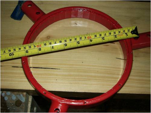
The blades need to be removed from the spigot shaft to set the pitch and the overall diameter of the blades, to make sure all the blades are exactly the same angle and diameter a jig was used to do the initial setup.
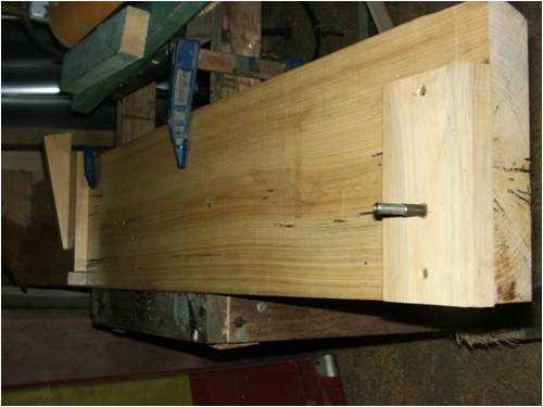
The original rivets where drilled out of the blade, showing the reason for the pitch differences between the blades as the peening of the rivets had bent their shanks causing some misalignment. I am replacing these rivets with 1/4 bolts grade 5 high tensile, by drilling from both side of the blades into the spigot shaft with a 3/16 droll, the same size as the original rivets then drilling right through with a slightly undersized drill and final drill to size 1/4 inch, this makes for a good fit of the bolts, nearly as good as a reamed hole.
When fitting bolts like this it is important that none of the thread is in the loaded section of the holes, do this by selecting a bolt with a unthreaded shank slightly longer than the thickness of the blade and packing it with washers to get the clamp required, the outer bolt can also be used to add a washer or two when balancing, very handy. Make sure to use nylock nuts for security and do not over-tighten as it will compress the spigot tube about 4 ft lb is good.
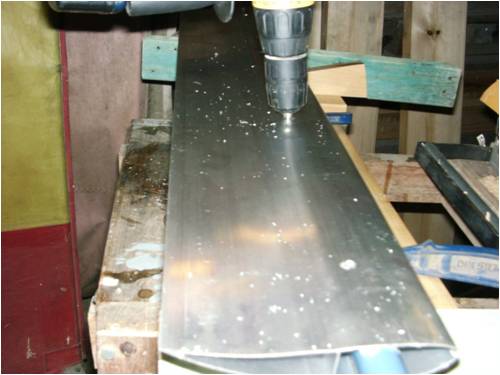
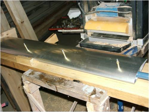
To hold the blades in alignment during drilling the other side of the blade I used sheet metal pins called cleco's, but a aluminium rivet or two can do the same job, and drill it out when finishing the drilling in the Jig.
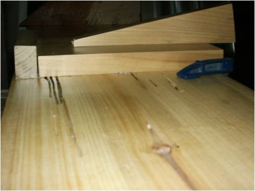
In this picture the angle block to set the initial angle of all the blades is visible it is cut at 12 degrees and when the blade is laid in it it gives an angle of 8 degrees at the cord line of the airfoil, this is the angle Phill has found the blades to be most efficient at so no reinventing the wheel there.
A stepped pin is fitted to the jig to hold the spigot shaft to the correct angle while drilling the holes. The reason for the stepped pin is to make sure the blades go onto the spigots on the rotor correctly as the bolts that hold them in are stepped.
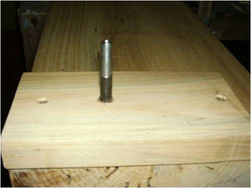
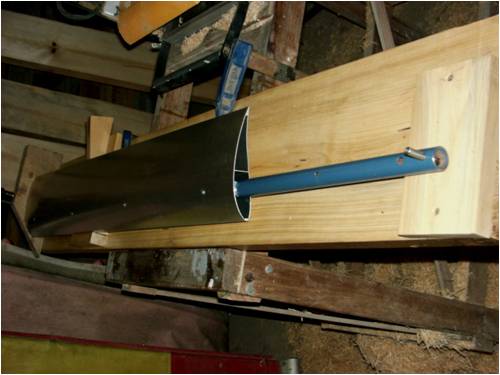
Here is the blade in the jig prior to drilling the bolt holes, the stop block at the end was to assure that all the blades are exactly the sale length from the stepped location pin, note here the length of the shaft before the airfoil section, this in effect extends the length of the blade to 2.8 meters allowing more torque to the alternator in operation, with a larger swept area it can absorb more energy from the wind. I have found the blades will self start at 1.1 ms and keep turning down to .7 ms they start producing a little bit of power above 2ms The airfoil section is a high lift high energy section designed for low wind speeds, so it seems to be a good combination.
You might wonder about there being no blade in the center of the turbine caused by shifting the blades further out on the spigot shaft, as it happens the primary energy collected by the blade is in the outer 1/3 of the swept area, so it makes very little difference, a constant cord blade like this without pitch change over it's length is a compromise in theoretical efficiency, but the fact of the matter is, it works very well in practice.
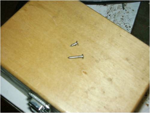
One other little thing I did was to increase the length of the self tapping screws that hold the outer end caps on, as several of the little screws where partly stripped in the initial assembly of the blades, be sure to use SS screws to avoid electrolysis with the alloy blade. I did this so the end caps where more secure as if one came off at high rpm it would cause a serious imbalance in the rotor turbine and could destroy the machine, I am not paranoid you know.
When the blades are assembled on the rotor prior to balancing the final pitch trim can be set with a protractor or inclinometer, I purchased a digital one on fleebay for $30, and thats half the price quoted for a bubble and dial one at the hardware supplier, the only thing is it reads to .01 degrees so needs a steady hand to use it so no party the night before.
The blades where end weighed before assembly and found to be within 1 gram of balance so thats a good starting point for overall blade balance.
More later when the ends of my fingers heal from all this typing and my head stops spinning.
All the best
Bob

Foolin Around |
| |
Tinker

Guru

Joined: 07/11/2007
Location: AustraliaPosts: 1904 |
| Posted: 02:44pm 26 Nov 2010 |
 Copy link to clipboard Copy link to clipboard |
 Print this post |
|
Hi Bob,
You suggested using ss scews on the aluminium blades to avoid electrolysis. This is actually a bad combination, I have a sail boat and plenty of experience with ss screws on aluminium.
The best material would be monel but I only have seen pop rivets made of that. When using ss screws you may get away by using a compound like Duralac on the thread and around the screw head to stop the dreaded white powder forming. If I can I insulate the ss screw head with nylon or fiber washers as well.
For the end caps why not using Sikaflex instead of the screws? This stuff is very strong yet flexible enough to allow for different expansion rates. As long as there is no peeling force on the parts it would be my choice material to fit the end caps.
Klaus |
| |
VK4AYQ
Guru

Joined: 02/12/2009
Location: AustraliaPosts: 2539 |
| Posted: 10:05pm 26 Nov 2010 |
 Copy link to clipboard Copy link to clipboard |
 Print this post |
|
Hi Tinker
I agree that its not Ideal to use any other metal than alloy to alloy in a marine environment, and even that can cause problems In this case the end cap is plastic so it forms an insulation under the head and perhaps a bit of paint or epoxy on the threads may help to keep the moisture out for the final assembly.
I have used sikaflex for bonding alloy to alloy in wing and blade construction and its real good on flat surfaces, but here it is bonding PVC to a marrow strip of alloy 1.6 mm I am not so confident, cause if the end cap comes off the balance problem is back.
I think the whole mill would be subject to corrosion problems in a marine environment, and wouldn't recommend the mill be used in these. As with all constructions there is a mix of metals that would be nearly impossible to prevent galvanic corrosions occurring when mixed with a salt laden atmosphere.
Thanks for your information and suggestions, this whole thing is a forum for learning and helping one another and all suggestions are more than welcome .
All the best
Bob
Foolin Around |
| |
Tinker

Guru

Joined: 07/11/2007
Location: AustraliaPosts: 1904 |
| Posted: 12:54pm 27 Nov 2010 |
 Copy link to clipboard Copy link to clipboard |
 Print this post |
|
Bob, on my boat the masts are painted carbon fiber. The sail track is plastic. No holes are allowed in the mast so the track was stuck on with hi strength Sikaflex. Its holding very well with a 23 sq m sail trying to rip it off  . .
Klaus |
| |
VK4AYQ
Guru

Joined: 02/12/2009
Location: AustraliaPosts: 2539 |
| Posted: 12:16am 28 Nov 2010 |
 Copy link to clipboard Copy link to clipboard |
 Print this post |
|
Mi Klaus
You are right the sikaflex is top stuff, I have used it for years bonding alloy in blades and wings, but to open a tube to use several grams sticking the end caps on didn't make good economic sense to me plus I wasn't sure it would bond to the plastic end caps as I found it lets go on poly pipe type plastic.
The screws where ten cents each and equal weight so frugality won out. As it will be up and down a few times in the next few months the easy removal of the end caps was a bit of a priority as I want to fit some tip winglets to try for a bit more lower end torque.
All the best
Bob
Foolin Around |
| |
KarlJ

Guru

Joined: 19/05/2008
Location: AustraliaPosts: 1178 |
| Posted: 10:50am 28 Nov 2010 |
 Copy link to clipboard Copy link to clipboard |
 Print this post |
|
nice one bob 
Luck favours the well prepared |
| |
VK4AYQ
Guru

Joined: 02/12/2009
Location: AustraliaPosts: 2539 |
| Posted: 01:00am 29 Nov 2010 |
 Copy link to clipboard Copy link to clipboard |
 Print this post |
|
Hi Karl
Thanks mate its still a work in progress, but I am having fun
All the best
Bob
Foolin Around |
| |
| |
  Page 3 of 9 Page 3 of 9   |

