
|

|
Forum Index : Windmills : Started on the axial flux
| Author | Message | ||||
| Gizmo Admin Group Joined: 05/06/2004 Location: AustraliaPosts: 5078 |
Hi Poss Oh hold for the moment, got to watch the financials for a few weeks. My tenant hasn't paid rent for a month, so now I'm paying more in my own rent and mortgage than I earn. As soon as its sorted, if its sorted, I'll get back into it. Glenn The best time to plant a tree was twenty years ago, the second best time is right now. JAQ |
||||
Poss Newbie Joined: 27/09/2009 Location: AustraliaPosts: 30 |
Might have to send around the heavies!  Are you going to wind the coils for the stator yourself? What voltage will you be running? I would be interested in getting the laser cut parts from you so I can build one too..Poss Are you going to wind the coils for the stator yourself? What voltage will you be running? I would be interested in getting the laser cut parts from you so I can build one too..PossA brave man may not live for long, but a careful man does not live at all. |
||||
| Gizmo Admin Group Joined: 05/06/2004 Location: AustraliaPosts: 5078 |
Hi Pos Yeah I'll be winding the coils myself, but a little different than usual. Most of the Axial Flux stators have the coils terminated internally, before poring the resin. I would perfer to bring all coil leads out, so I can play around with star/delta conbinations. I'm also thinking of winding two coils per coil, 2 in hand as it were, and keep the ends separate. That gives the ability to wire the coils in series or parallel. I'm aiming for a 24/48 volt stator. Once the design proves itself the CAD files will be available to anyone. I dont want to release them yet in case there is some fundermantal stuff up in the design that I havn't found yet. Glenn The best time to plant a tree was twenty years ago, the second best time is right now. JAQ |
||||
| domwild Guru Joined: 16/12/2005 Location: AustraliaPosts: 873 |
Great stuff, Glenn! Taxation as a means of achieving prosperity is like a man standing inside a bucket trying to lift himself up. Winston Churchill |
||||
| Joblow Regular Member Joined: 05/01/2010 Location: AustraliaPosts: 54 |
It surprises me that no one on this site (unless I missed it) has sugested using 'angular contact' bearings, they have the ability to cary both radial and thrust loads with much less friction than taper roller bearings. They can also be mounted in multiples, back to front, front to back, back to back and front to front, thay also come in standard program sizes so can directly replace other types of standard program bearings. The man who never made a mistake never made anything |
||||
| OneToRemember Newbie Joined: 19/05/2008 Location: United KingdomPosts: 11 |
Hi guys You may find this axial turbine plan of help if you haven't seen it before. Here's the Link http://www.onetoremember.co.uk/xcart/Axial-Flux-Windmill-Pla n-2002.html http://www.onetoremember.co.uk/xcart/Axial-Flux-Windmill-Pla n-2002.html just add it to your cart and and a zero price then check out with a valid email and then you can download it. There are lots of other free plans too here is the link http://www.onetoremember.co.uk/xcart/free_ebooks.html http://www.onetoremember.co.uk/xcart/free_ebooks.html Hope that helps a little bit. Regards great books @ http://www.Onetoremember.co.uk Buy and sell renwable energy bits and pieces free at http://www.EnergyBook.co.uk |
||||
Poss Newbie Joined: 27/09/2009 Location: AustraliaPosts: 30 |
A tapered roller bearing is a type of "angular contact" bearing. Is there a specific type you are suggesting. The bearings that Gizmo intends to use are "Off the shelf", inexpensive and readily available and see years of service on a car, which would put the bearing I would have thought under more "Load" than a turbine. These bearings also go directly into a Hub that is also "Off the shelf" and so on. Perfect for most people who want to have a go at building their own turbine...Poss. A brave man may not live for long, but a careful man does not live at all. |
||||
| Gizmo Admin Group Joined: 05/06/2004 Location: AustraliaPosts: 5078 |
The plans linked to my OneToRemember are one of Hugh Piggott early designs, a good work horse but a little dated, he's made some improvements since then. You can get Hugh's latest plans from his site http://www.scoraigwind.com/ Yeah I agree with Poss, there are better bearings out there as Joblow suggests, but you cant go past a vehicle wheel bearing for ease of use, rugged reliability and price. Glenn The best time to plant a tree was twenty years ago, the second best time is right now. JAQ |
||||
| Joblow Regular Member Joined: 05/01/2010 Location: AustraliaPosts: 54 |
Sorry Ross, but I must disagree that taper rollers are a type of angular contact bearing, I have started a new post with some explanation and diagram of an angular contact if anyone is interested  The man who never made a mistake never made anything |
||||
Poss Newbie Joined: 27/09/2009 Location: AustraliaPosts: 30 |
Design features Tapered roller bearings have tapered inner and outer ring raceways between which tapered rollers are arranged. The projection lines of all the tapered surfaces meet at a common point on the bearing axis. Their design makes tapered roller bearings particularly suitable for the accommodation of combined (radial and axial) loads. The axial load carrying capacity of the bearings is largely determined by the "CONTACT ANGLE" á (fig); the larger á, the higher the axial load carrying capacity (fig). An indication of the angle size is given by the calculation factor e; the larger the value of e, the larger the contact angle and the greater the suitability of the bearing for carrying axial loads. 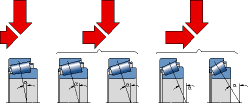
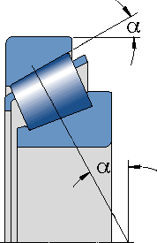
Angular contact tapered roller bearings and it's Poss... A brave man may not live for long, but a careful man does not live at all. |
||||
Downwind Guru Joined: 09/09/2009 Location: AustraliaPosts: 2333 |
Guys this is all very interesting on bearings but i will let you in on a little seceret.......Psst...Dont tell anyone.... One thing Glenn didn't want was a pissing competition on bearings within this thread. It distracts from what this thread is about, and if you want to argue over bearings than i would say start your own new thread elsewhere. Pete. PS:- I see Joblow has started a new threat on bearings and think it would be a better place to continue this discussion Sometimes it just works |
||||
Poss Newbie Joined: 27/09/2009 Location: AustraliaPosts: 30 |
Woops I thought this was all about people learning something new. As a newbie maybe we moved away from the main topic but we were arguing a point that we were passionate about. Some people on this site are to quick to jump on peoples heads without using a little tact..."Sarcasm is the lowest form of wit". A brave man may not live for long, but a careful man does not live at all. |
||||
| arklan Newbie Joined: 18/08/2010 Location: AustraliaPosts: 29 |
the more things change, the more they stay the same anyway, what kind of blades are you going to stick on this beast gizmo? wood carved or some extruded ones? |
||||
| Gizmo Admin Group Joined: 05/06/2004 Location: AustraliaPosts: 5078 |
Well I want to have a go at Oz's chain saw blade technique. http://www.thebackshed.com/windmill/articles/ChainsawBlades. asp I've tried making timber blades before, but the time and effort has always put me off. Oz's method takes a lot of the hard work out of making 3 identical blades. I have chainsaw, so time to have a go. The steel plates I had lasercut were for timber blades anyway. This week I'll temporarily fit the magnets and wind a small test coil. Glenn The best time to plant a tree was twenty years ago, the second best time is right now. JAQ |
||||
| Gizmo Admin Group Joined: 05/06/2004 Location: AustraliaPosts: 5078 |
Today I met up with Trev at his school and got the magents and some magnet wire from him. While I was there I had a look around his schools new trade training center, things sure have changed since I was at school, we didn't learn tig welding for one thing! Here's the box of magnets. 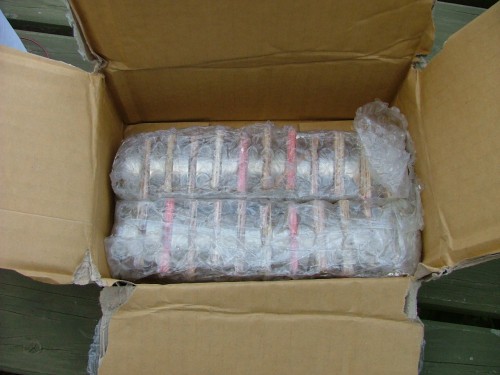
They are 50mm dia by 12m thick ( 2 inch by half inch ). I have to say, these things are dangerous to handle, you need to think about every move you make. This weekend I'll temporarily fit them to the alternator plates and wind a test coil Glenn The best time to plant a tree was twenty years ago, the second best time is right now. JAQ |
||||
| JimBo911 Senior Member Joined: 26/03/2009 Location: United StatesPosts: 262 |
Wow, now those are some bad ass magnets. Glen you may have to put on some gloves made of concrete just in case? Jim |
||||
| Gizmo Admin Group Joined: 05/06/2004 Location: AustraliaPosts: 5078 |
OK, some more progress today. I temporarily fitted the magnets to the front and rear magnet plate. Those magnets are a tough little buggers to handle, its a constant fight to get them onto the plate without loosing a finger, but once there, they can be easily slid into position. This is the rear magnet plate, with Bogie in the background. Bogie likes to play in the rain and chase dogs, go figure. 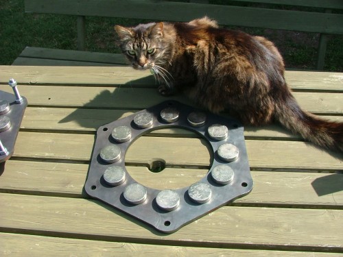
Next we see the front magnet plate, with jacking screws fitted. The jacking screws are about 300mm long, a bit overboard but better to play it safe. 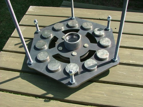
I wound a test coil, 10 turns, and taped it to the dummy stator. The stator is in position on top of the front magnet plate. 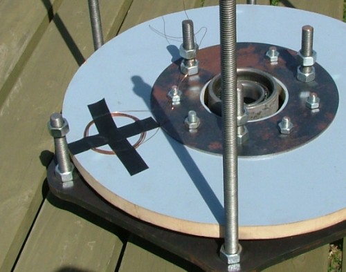
Here it the rear magnet plate in position ready to be lowered down. I found I could turn the nuts by hand till the rear plate was about 150mm from the front plate, when the magnet force was starting to really kick in. 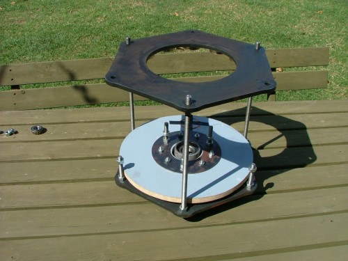
The rear plate is almost home, enough to engage the 3 other spacer threads. 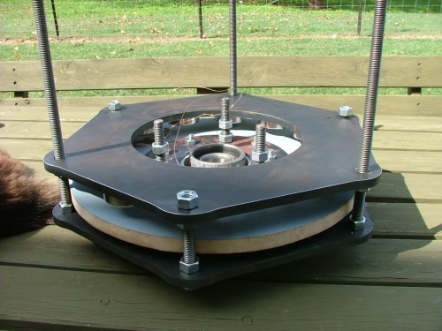
Once I could fit the nuts to the spacer threads, the alternator was safe and I replaced the jacking threads with the 3 remaining spacer threads. The alternator can now be fitted to the windmill for final adjustment. 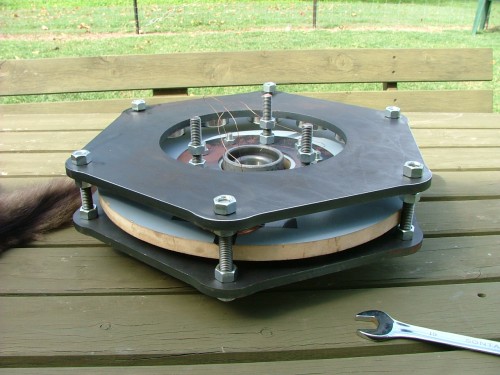
Here's the stub axle and stator positioning plate. Once the windmill is completed, this is what we have when the alternator is removed. 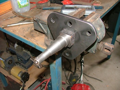
Ready for testing. 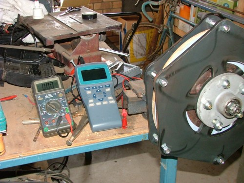
I have a small hand held CRO which can display the peak voltage and waveform as I spin the alternator. I used my camera to take photos of the screen as I spun the alternator. By taking photos I get time to read the scale and work out the sine wave duration, and with a bit of maths calculate the RPM. 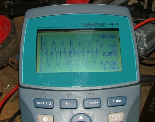
This is what I ended up for my 10 turn test coil. Magnet spacing was 20mm. Volts RPM 1.63 95 1.72 100 2.28 133 Now I start some research to find the best blade diameter, tsr, and coil count to suit this alternator. Glenn The best time to plant a tree was twenty years ago, the second best time is right now. JAQ |
||||
| VK4AYQ Guru Joined: 02/12/2009 Location: AustraliaPosts: 2539 |
Hi Glenn Good job mate it really shows how it comes together and the volts on a ten turn coil is impressive, what air gap are you running for this test and how much difference to the voltage readings are you anticipating when the coil is in its final resting place. All the best Bob Foolin Around |
||||
| Ghetto Newbie Joined: 01/09/2009 Location: AustraliaPosts: 14 |
wow, I'm blown away by the voltage your making on 10 turns as well! .  Is the magnet size giving you the performance? Is the magnet size giving you the performance?
Very nice clean design and construction. Bogie reminds me of cat, always hanging around whenever you tinkering on something. I'd like to think its love but I think it has more to do with the low chance that I **may** give him more food 
Cheers, Rob |
||||
Trev Guru Joined: 15/07/2006 Location: AustraliaPosts: 640 |
It may be the magnets. These magnets are much stronger than what is generally used. These magnets are N50M. N is Neo, 50 is grade and M is temp rating of 100C. They are 50mm diameter x 12.5mm thick. I must say Glenn, is looking very good. Trev @ drivebynature.com |
||||