|

|
Forum Index : Windmills : New 500W+ Chinese Windmill
| Author | Message | ||||
Downwind Guru Joined: 09/09/2009 Location: AustraliaPosts: 2333 |
One thing i would be interested to know is, was there any rpm recorded when the mill was shorted. I don't think the data logger would show this, but suspect it broke away from being stalled in high winds. I personally feel ALL iron core mills should be controlled through a dump load and not via shorting the windings. If it do break away from stalled in high winds there is nowhere for the energy to go except circulate within the windings causing mass heat. From my understanding it was producing power up to the point it was shorted, and then dead the next day, this would imply to me it broke away over night while the windings were shorted. 20-50 rpm with shorted windings could be a 1000 watts of energy produced even at very low voltage. I think Gordon quoted me recently with his mill shorted and it spinning at 5 rpm it was still producing over 10 amps back into the windings The ventilation holes should help but the energy needs to be removed and controlled away from the windings. The other problem that might come into play is with shorted windings it can still produce mass power at low rpm and there will be little air flow through the ventilation holes at low rpm. It may be better to let it spin up and dump the power to give better air flow across the windings. Also 1600 watts from a 500 watt mill is also pushing the friendship too. Pete. Sometimes it just works |
||||
fillm Guru Joined: 10/02/2007 Location: AustraliaPosts: 730 |
Hi Pete , To produce 1000w of power in the windings there first has to be 1000w of energy being produced by the blades . Once blades are in stall very little power can be produced , the big Amp hit is when the switch is thrown at high RPMs, I think you will find that Gordons at stall, if it was producing 10 amps it would be at low voltage - eg 5V which would only be 50w. I would think if it did break away while it was shorted, with the heat that could generate it would have done a lot more damage or even to the point of catching on fire . PhillM ...Oz Wind Engineering..Wind Turbine Kits 500W - 5000W ~ F&P Dual Kits ~ GOE222Blades- Voltage Control Parts ------- Tower kits |
||||
| VK4AYQ Guru Joined: 02/12/2009 Location: AustraliaPosts: 2539 |
Hi Phill It looks to me like a shorting switch at high rpm damage, as it had caused power related damage to everything, its a bit of a chicken and egg situation, but if it was shorted at to high rpm it wouldn't stop due to wind energy and blade inertia. I wish I had wind like that at my place too. I am looking at making a amp limiter on the output and let the volts go higher and use a switch-mode down converter to 27 volts as my bump load is at the batteries already so it can absorb the energy there. It's a real juggling act trying to get the power at low wind speed then loose it at high speed. I think around 30 amps roll off in delta should protect the windings as they are 5 in hand. The cooling holes will help the heat buildup, as Amacks got a lot of trapped heat as indicated by the flow pattens on the end caps, trapped inside the sealed unit with nowhere to go, just buildup. All good fun getting a quart out of a pint pot. All the best Bob Foolin Around |
||||
| vawtwindy Newbie Joined: 23/10/2010 Location: IndiaPosts: 31 |
Phill M how many windings per phase?, is it connected star(wye) or delta? |
||||
| VK4AYQ Guru Joined: 02/12/2009 Location: AustraliaPosts: 2539 |
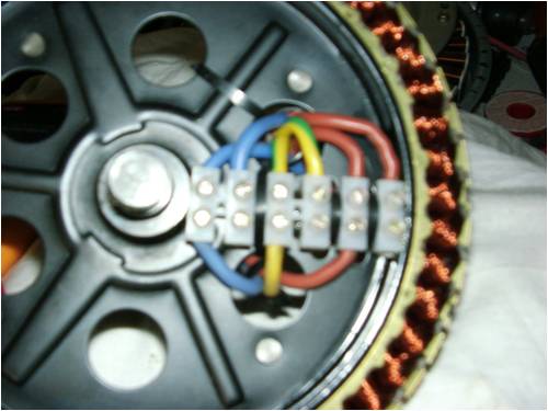
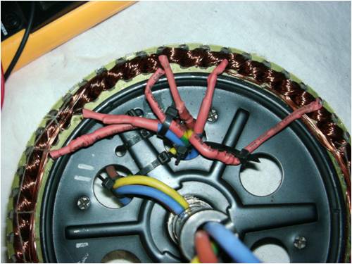
Hi VAWTWINDY They are connected in STAR as original, here is a photo of mine reconfigured as Phill suggested so the terminals are under the front cover so all thats required is to remove the front to have access to the windings.  access access

The termination of the windings is on the rear side of the stator, these wires are lengthened and fed through the holes in the stator to the front to the terminal block so they can configured as star or delta as required. I think from memory there are sixty coils wound five wires in hand. All the best Bob Foolin Around |
||||
| JimBo911 Senior Member Joined: 26/03/2009 Location: United StatesPosts: 262 |
I would have to agree with Pete as far as shorting out iron core machines. In the past my mill(Neos F&P 60)was shorted out prior to VERY high winds and ended up on the ground. I am sure she broke away from shorting and I ended up with a run away mill. Wasent home at the time so I have no way on knowing what the tail was doing. Jim |
||||
| VK4AYQ Guru Joined: 02/12/2009 Location: AustraliaPosts: 2539 |
Hi Jimbo I have tried turning my mill with the windings shorted out and it has a lot more resistance than quoted in Altons blade stall to rotation requirement, so if it was stopped before the heavy wind event I can't see it winding up again. The totally stalled blades would generate very little torque. If you look at the damage to the windings in the photo you will see that one or two windings suffered the highest current and overheated badly, it makes me wonder if that one phase somehow shorted out during the application of the shorting brake and the heat generated by this event was the main cause of the damage. I have now modified mine to try to solve the problem and will post some photos once it is finished. All the best Bob Foolin Around |
||||
| GWatPE Senior Member Joined: 01/09/2006 Location: AustraliaPosts: 2127 |
Hi Bob, Alton's calculator calculates torque figs on the blade profile as used in its own formulae. If you have the same blade profile and shape then the statement you make above is true. With a different blade shape and profile, then torque would need to be recalculated for it. Gordon. become more energy aware |
||||
| VK4AYQ Guru Joined: 02/12/2009 Location: AustraliaPosts: 2539 |
Hi Gordon You are exactly right on the blade profile as Alton profile is a higher speed profile than the high lift profile on the Chinese Mill which is more efficient at lower speed and has a higher CL at lower speed for the same angle of attack. However when stopped with the blade fully stalled it is a blade surface area and angle of attack that produces stalled torque and as the Alton blade is tapered it will have a lower stalled torque, some rough calculations on the Chinese Extruded blade led me to believe that it would have about 30 % extra start up torque, it still would need more wind pressure to unstall the blade than a 40 ms gust would produce, I do not have the exact figures for the airfoil shape so thats an estimation only. The reason I believe there was another factor involved was the uneven cooking of the windings as shown in the picture. All the best Bob Foolin Around |
||||
AMACK Senior Member Joined: 31/05/2009 Location: AustraliaPosts: 184 |
BOB, All the windings are cooked the same amount. You can not tell from the photo but I can tell you it was an even cook. I have not posted in a while but may be making some post shortly with alot of photos. Some of the comments in this post are a bit off the mark. I am going to sit on things for a bit longer before I do. It seams alot of comments in this post are saying I shut the thing down when it was running flat out, which I did NOT. I think people are jumping the gun here and do not have the full picture or all the facts.. AMACK  *Note to self 1. Make it thick 2.Make it heavy. 3.Make it stronger than it should be. 4. Don't rush the first job as the second job will cost more and take mor |
||||
| GWatPE Senior Member Joined: 01/09/2006 Location: AustraliaPosts: 2127 |
Hi Bob, the Alton's calculator determines the torque produced by an individual blade completely stopped. I believe the constant chord blade will produce more than 30% more torque, and the torque produced is a function of the square of the windspeed. Windspeeds were measured at over 30m/s. factor in some rpm and this complicates the figs more. the I^2R losses are the usual wire heating aspect. My recording logs show that the recorded maximum average power for a 10sec integrated logging period is approx half that of the maximum average power for a 2sec integrated logging period. The instantanous peak logged power is approx double the 2sec avg. The double power produces 4X the wire heating for that period, so the average wire heating for the longer averaged time could amount to 2X that calculated for the power level. I think we will not really know what has happened without more controlled testing and logging. This wind site may just not be a good location for this windmill. I have seen even the best brand windmills fail electrically and mechanically. I think some refinements are still needed and possibly some locations will still challenge the design. A smaller bladeset and earlier furling may offer the simplest solution here. Gordon. PS edit:- Hi AMACK, saw your post after I posted mine. You would be having some good winds at the moment, as I am. Do you have access to the windspeed profile at your location, as this will help to determine if the windmill sizing is OK. become more energy aware |
||||
AMACK Senior Member Joined: 31/05/2009 Location: AustraliaPosts: 184 |
Gordon, Do not have a mill going it's cook again. less then an hour. AMACK *Note to self 1. Make it thick 2.Make it heavy. 3.Make it stronger than it should be. 4. Don't rush the first job as the second job will cost more and take mor |
||||
| brucedownunder2 Guru Joined: 14/09/2005 Location: AustraliaPosts: 1548 |
Sorry for you Amack ,,, It's not a good feeling ... But life goes on ,my friend . Take a deep breath and get back into it... Cheers and understanding Bruce Bushboy |
||||
| VK4AYQ Guru Joined: 02/12/2009 Location: AustraliaPosts: 2539 |
Hi Andrew Sorry to hear it cooked again so quickly, you must have enormous winds there, lucky and unlucky. Sorry to get the assumption wrong on the windings I was just going on the photo not the real thing. The main problem is getting a quart out of a pint pot as the original design was for 1000 watts only and I suspect that would be a less than 100 percent rating. On the switching at high speed I believe if you did that, it would really have melted the lot. Gordons comment an a smaller blade set may help a bit but would need the furling set lower to as he stated because the power absorbed by the blades at high wind speed is many times the rating of the generator. Once my first one is up and running I am going to get a second one going but let the volts go up instead of the amps and use a switch mode down converter to come back to 27 volts. A spin up in the lathe to 500 rpm yielded over 100 volts into a dummy load so even in delta it can pump out the volts. It did 12 amps at 110 volts with no heating at this level of power so I would like to see what yours was doing in a high wind. I went to 700 rpm and got nearly 200 volts with the 50 amp meter off scale. My test dummy load is a 3000 watt 220 volt heater and a 10000 watt industrial heater fan so it is a resistive load. Only run this level fo less than a minute and there was heat build up. All the best Bob Foolin Around |
||||
Downwind Guru Joined: 09/09/2009 Location: AustraliaPosts: 2333 |
While we are kicking the theory cat here, ill add my 20c worth of gut feelings. Firstly is trying to be too greedy with a combination that had not been well tested over time. I see windmills like loading a trailer, its done a stage at a time and not as one big load, so as to blow the tires and invert the springs. I feel the blade set is wrong for this type of mill and is far too powerful out at the tip with a constant cord. To add to the problem is the weight of each blade as the rotating mass can not loose speed fast enough, compounding the problem. I still think the main problem here was believing the phases could be shorted to control the mill. Regardless of what magnets or style of windings the alternator has this is a disaster waiting to happen with an iron core machine, it always has been and always will be. The energy needs to be drawn away from the mill and dealt with in a dump load, this removes most of the heat that is generated from the energy within the coils. In both cases the mill was generating power when shut down and was obviously not cooked at that point or it would not have been generating power. Both times i believe it broke away from stall while the phases was shorted and is when it cooked itself. I respect the work that both Andrew and Phill have done here with this mill, but feel it is the wrong combination of design for the wind conditions for the location. It is asking a boy to do a mans job under the conditions. I dont think any amount of design changes would make this mill robust enough for the location conditions. If it was myself attempting to fly this mill in this location, the first change i would make would be a different blade set that had some degree of self limiting the power they were able to make under load. The present blade set is like running a diesel motor without some form of a govoner, as they will keep increasing in power output until the weakest link lets go, and in this case it appears to be the windings. Thats my 20c worth of gut feelings. Pete. Sometimes it just works |
||||
| VK4AYQ Guru Joined: 02/12/2009 Location: AustraliaPosts: 2539 |
Hi Pete I think you are right in what you say because it is a good little low wind speed mill but with those very efficient blades the generator can be overpowered in consistent high wind speeds. By letting the voltage increase it will do 10 kw with no effort for short bursts, but the wind catching capacity of these efficient blades can catch more than double that at high wind speeds. To overcome that there needs to be a really good furling system in place, and a voltage down converter to capture the higher voltage. I do think though, that the blades are capable of delivering more power to the alternator than it can handle even when fully furled, for instantaneous peak power for a few seconds in a gust it could handle it it is just when it is continuous thats the problem. On mine I am going to increase the furling angle 10 degrees to try to limit blade speed, not that I think I need it at my place very often. Could the furling system be made to track the rpm of the alternator by using a linear actuator tied to a frequency control, using a picaxe. I hope to have mine up and flying next week, and will get another one from Phill to experiment with. The super efficiency of these little generators is their good and bad point, they are to efficient for their own good in high winds. Ipulled my other generator down last week to check it out and all is well, it was doing over 50 amps in the gusts several weeks ago and was actually bending the top of the mast a bit, so had to put an extra set of guy wires on it. All the best Bob Foolin Around |
||||
| GWatPE Senior Member Joined: 01/09/2006 Location: AustraliaPosts: 2127 |
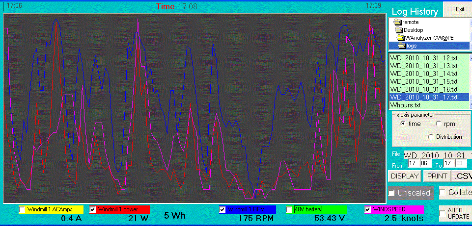
Hi Bob, here is a graph of a few minutes logging of my mill at 2 sec intervals. I think an electronic controlled actuator for furling based on rpm will wear out quite quickly. Dampening the system will negate the furling benefit. 
Gordon. become more energy aware |
||||
| VK4AYQ Guru Joined: 02/12/2009 Location: AustraliaPosts: 2539 |
Hi Gordon I see what you mean, the rpm is all over the place, looks like I will have to go back to the high voltage fixed maximum amps Idea, as its the amps thats doing the damage on extended power intervals. If I set the maximum amps at 40 amps that should be sustainable within the design of the generator and let the volts climb then down switch to 27-6 volts for the total power. The furling is also critical to prevent a full runaway. All the best Bob Foolin Around |
||||
| KarlJ Guru Joined: 19/05/2008 Location: AustraliaPosts: 1178 |
Ahh maybe the F&P dual not so bad after all. looks like -given it will never burn out a tough little beast even if i cant get 1KW out of it... perhaps 48V is the solution = 1/2 the amps for the same power. Luck favours the well prepared |
||||
| JimBo911 Senior Member Joined: 26/03/2009 Location: United StatesPosts: 262 |
Can't say I am as knowledgeable as some of you guys but I can comment on some things I've learned from my mill. Again, I would have to agree with Pete shorting out this alternator will not keep the blades stalled. My mill disaster is all the prove I needed to convince me of this. It seems obvious the blade set on this alternator create more then enough torque to over power the windings. In an attempt to increase the KWH production of my mill during the summer months (low winds)I increased the angle of attack on my blade set my thoughts were to get the mill spinning sooner and help increase torque in lower wind speeds. I was correct the mill did start spinning sooner or at lower wind speeds and created more torque. I also noticed that the lift effect was diminished at higher RPM. As the RPM increased the blades became a bit nosier and made more of a swishing sound. I also noticed that the mill was not spinning near as fast as it normally would with the blades set at a lower angle of attack. The greater angle of attack created more drag and more noise but kept the RPM down from its normal speed. This alternator may be better served by decreasing the swept area (lowering torque)and increasing the blade angle a bit to help with controlling higher RPM. After rebuilding I am just about ready to fly my mill again. I will be decreasing the swept area a bit as I feel my blade set can easily over power my single stator F&P. I have redesigned the tail to a much lighter unit to help with furling hopefully this should help me keep things under control during high winds. Just mt thoughts. Jim |
||||