| |
  Page 3 of 6 Page 3 of 6   |
| Author |
Message |
MacGyver

Guru

Joined: 12/05/2009
Location: United StatesPosts: 1329 |
| Posted: 07:18pm 04 Jun 2010 |
 Copy link to clipboard Copy link to clipboard |
 Print this post |
|
[Quote=oztules]but you must get a firm grip on power expectations
Key words here would be "firm grip"; I've never had one, not in 62 years (I round up). I think I can put things into a better perspective by telling you more about how I tick.
First off, my middle initials should have been E.E. and that would stand for "Enjoy Everything".
My basic belief is that all things are possible and I can do all things. With that in mind, you can readily see why I dip my fingers into so many pies. I merely believe "I can" and jump in feet first. If things go south, I merely take a different pathway and continue on. Life is a blast!
For a reality check, last evening I knocked the little windmill frame off my work bench and caught it by the tail frame. It broke! That all-aluminum "weld" broke! No matter; that's what gussets are for, right? See? Always a plan B; always!
Like the guy said in the movie, "Damn the torpedoes, full speed ahead!" That's my M.O. I'm just going to go ahead and build this thing and if it works, I'll share the results. If it doesn't work, I'll have another dandy paper weight and a great story to tell. See? Win-win! 
Of course, if things go south (as they often do) I'll share that too. No sense giving anyone a false sense of things, right?
. . . . . Mac
Nothing difficult is ever easy!
Perhaps better stated in the words of Morgan Freeman,
"Where there is no struggle, there is no progress!"
Copeville, Texas |
| |
MacGyver

Guru

Joined: 12/05/2009
Location: United StatesPosts: 1329 |
| Posted: 07:28pm 04 Jun 2010 |
 Copy link to clipboard Copy link to clipboard |
 Print this post |
|
Tip Speed Ratio or TSR
I'll admit I'm not the sharpest tool in the shed. That being said, I culled this definition from Wikipedia:
"The tip speed ratio λ (lambda) or TSR for wind turbines is the ratio between the rotational speed of the tip of a blade and the actual velocity of the wind. If the velocity of the tip is exactly the same as the wind speed the tip speed ratio is 1. The tip speed ratio is related to efficiency, with the optimum varying with blade design.[1] Higher tip speeds result in higher noise levels and due to large centripetal forces; stronger blades."
Sure as I'm a foot tall, there are probably lots of other folks wondering what the heck TSR means besides me. Now we know!
. . . . . Mac
Nothing difficult is ever easy!
Perhaps better stated in the words of Morgan Freeman,
"Where there is no struggle, there is no progress!"
Copeville, Texas |
| |
MacGyver

Guru

Joined: 12/05/2009
Location: United StatesPosts: 1329 |
| Posted: 07:31pm 04 Jun 2010 |
 Copy link to clipboard Copy link to clipboard |
 Print this post |
|
[Quote=MacGyver] I just sent a PM to Trev to see if he can help me by casting several parts for a controllable-pitch hub.
Got an email from Trev; he's too busy, so this isn't going to happen, at least not the way I'd envisioned it. It'll happen though; hide and watch.
. . . . . Mac
Nothing difficult is ever easy!
Perhaps better stated in the words of Morgan Freeman,
"Where there is no struggle, there is no progress!"
Copeville, Texas |
| |
JimBo911

Senior Member

Joined: 26/03/2009
Location: United StatesPosts: 262 |
| Posted: 11:45pm 04 Jun 2010 |
 Copy link to clipboard Copy link to clipboard |
 Print this post |
|
Hey Mac
Watching your mill come together makes me want to run out to the shop and build something!
Yeah, love that San Diego weather. 
Jim |
| |
MacGyver

Guru

Joined: 12/05/2009
Location: United StatesPosts: 1329 |
| Posted: 08:11pm 06 Jun 2010 |
 Copy link to clipboard Copy link to clipboard |
 Print this post |
|
June 6, 2010 Update
I've been at it again. This time, I had to walk up the street and around the corner to my friend Dan's garage shed. He has a way bigger lathe and he let me use it to cut the soft-iron magnet flux-backing plates for the ax-fx.
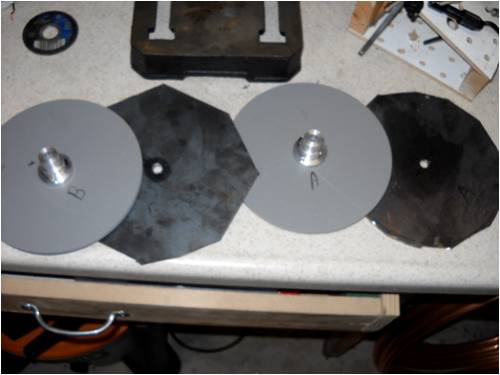
This is as far as I got yesterday. I used my high-speed grinder and cut
the 5/32 mild steel plate as round as I could get it.
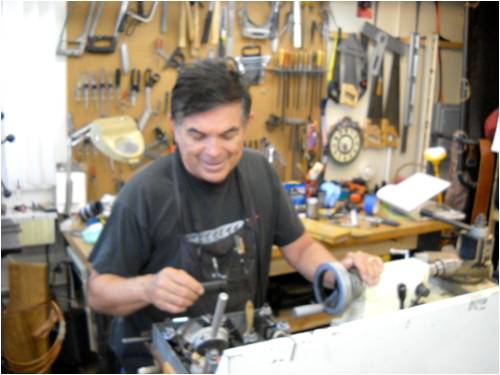
This is my friend, Dan Williams. He builds scale steam trains in his
garage shed. He's standing in front of his lathe.
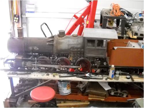
Here's what Dan builds. This is the steam locomotive and it weighs
600 pounds easily. This represents over 1,000 hours of work and it's
not finished yet.
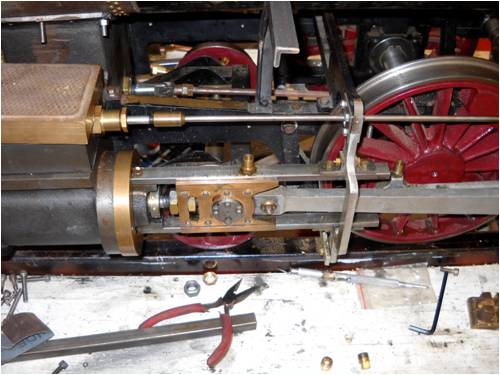
Here's a shot of one double-acting steam engine. There's one on each
side of the locomotive. Note the exquisite detail of this build. Dan is
an excellent machinist; many hours of practice!
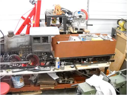
Here's the tender. It holds water and fuel oil (for the boiler) as well
as providing a place for Dan to sit and run the thing. When it's done,
it'll pull 20 or more cars with seats for people to ride around about a
1-mile scale track in a local park. Nice work Dan!
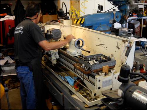
Here's a shot of the lathe. It's easily 5 times larger than my little toy.
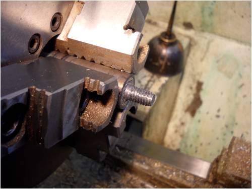
This is a shot of the "mandrel" Dan made to hold the iron pates. It is
made of cold-rolled steel round bar. A 5/16" shank was cut to fit my
pre-drilled plates. It was then threaded and a washer and nut hold the
plates to the lathe as it spins.
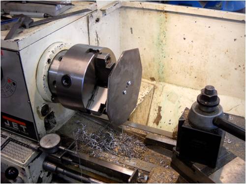
This is a shot of the bare plate chucked up in the lathe as we begin to
trim it down to size. At this point, we were using an aluminum mandrel
I made on my lathe, but as it turned out, it spun in his chuck, so a
new mandrel was fashioned to finish this job. That's the way it goes;
sometimes you spend your time fabricating tools. It's just the way it is.
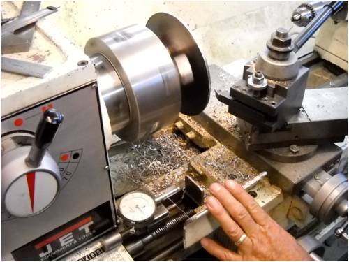
Here's one plate done. Note the micrometer Dan attached to the lathe
bed ways. That lets him zero in on a cut; way cool!
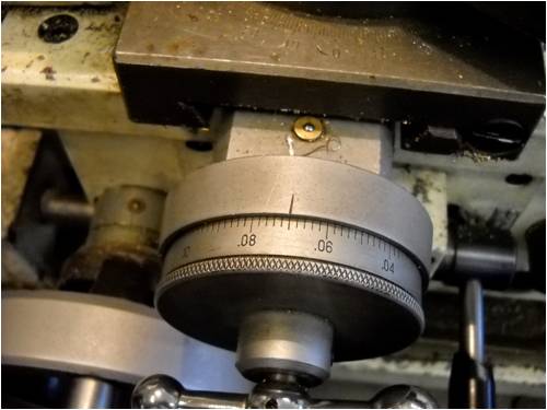
For those who don't own a lathe, this is the feed knob on the cross-slide.
The cross slide feeds the cutting bit across the face of the work. Each
little tick in the wheel = .002" and that's how we get things to fit so well.
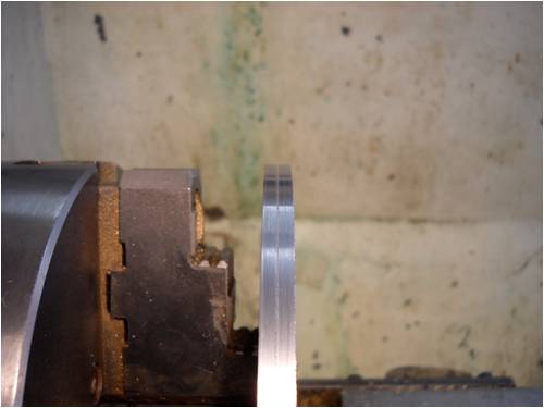
This shows the final cut. Both backing plates were mounted and cut
together. This holds the work "true" as well as assures each plate is
"exactly" the same size as the other. As the work spun, I trimmed the
outboard edge using a carbide cutter in the tool holder.
That's it for today. When the new magnets get here, I'll continue the build and update things here on the 4m. Thanks for watching!
. . . . . Mac
Nothing difficult is ever easy!
Perhaps better stated in the words of Morgan Freeman,
"Where there is no struggle, there is no progress!"
Copeville, Texas |
| |
Perry

Senior Member

Joined: 19/11/2009
Location: Posts: 190 |
| Posted: 01:25pm 07 Jun 2010 |
 Copy link to clipboard Copy link to clipboard |
 Print this post |
|
Looking good Mac,
Responding to one of your above posts I would have to say while building on an impulse is probably the most fun, it's also the least productive. Don't shy away too much from putting a pencil to paper to see if your goals are even possible in the first place. At this scale the math and the theories are pretty easy and tons of people here can talk you through them. Building a 500 watt genny and bolting on a 50 watt rotor is heading for hear ache, why not head it off at the pass now?
Too bad about the aluminum 'weld'. As I mentioned before, I bet the weld didn't break, it just didn't adhere to the aluminum because there is no penetration. You have to melt both the weld material and the target material or else it is just another shiny glue that will be pretty fragile. I'd create some features for the solder to flow into and try to use the tensile capabilities of the material to the best of its abilities.
Keep it coming,
Perry
|
| |
MacGyver

Guru

Joined: 12/05/2009
Location: United StatesPosts: 1329 |
| Posted: 03:31pm 07 Jun 2010 |
 Copy link to clipboard Copy link to clipboard |
 Print this post |
|
Perry
Thanks for the advise. In close examination of the "weld" what happened was I got the stuff too hot and actually degraded the aluminum to the point where it began to melt and when it did, it apparently oxidized.
Good point about the "relief" features. I think you're right about the "weld"; it's metal glue. Strong as nails itself, it's only as good as it sticks. So far, the other welds are holding very well. Also, I've simplified the frame as a result of the tail snapping off.
As for the proven vs the experimental portions of my builds, I'm somewhat stuck in the middle. The creative side of me says "go for it" no matter what the logical side (others' advise) says. The only detrimental part is by posting all my whacky ideas and methods on the 4m, I run the risk of leading someone astray; that's never my intention, so I'll have to temper what I post, I guess, eh?
Case in point: Over the weekend, I studied some basic electric theory as well as basic windmill-blade theory and I think I've come up with a winner. Instead of posting, then perhaps having to back paddle later, I've decided to build it and "if it works well" post it here. Sound like a plan?
Edit:
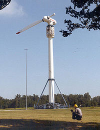
Just ran across this while studying up on "Betz Limit".
See, I'm not the only nut who tries
goofy designs. This is NASA's baby!
. . . . . Mac
Edited by MacGyver 2010-06-09
Nothing difficult is ever easy!
Perhaps better stated in the words of Morgan Freeman,
"Where there is no struggle, there is no progress!"
Copeville, Texas |
| |
VK4AYQ
Guru

Joined: 02/12/2009
Location: AustraliaPosts: 2539 |
| Posted: 06:12am 08 Jun 2010 |
 Copy link to clipboard Copy link to clipboard |
 Print this post |
|
Hi Mack
Nice to see your progress with the mill and now I think you will have to rethink the size of your blades a bit as it isn't a baby Genny it should pack a bit of a punch.
Good to have a friend with some serious gear like that as it saves beating the hell out of you transistorized lathe.
I look forward to the next installment.
All the best
Bob
Foolin Around |
| |
Don B

Senior Member

Joined: 27/09/2008
Location: AustraliaPosts: 190 |
| Posted: 10:48am 08 Jun 2010 |
 Copy link to clipboard Copy link to clipboard |
 Print this post |
|
Hi Mack,
Just getting back to your earlier post regarding tip speed ratio, there is a relationship between the number of blades in a wind turbine and the TSR that is appropriate for it.
A one blade turbine such as the NASA one in your photo can operate at a very high TSR (around 15), and can achieve efficiencies approaching the Betz limit (ie extracting almost 60% of the wind energy). With a high rotational speed, it is easier to match to an alternator. On the down side, it also has the lowest starting torque.
At the other extreme would be the multi bladed farm type windmill, which operates with a TSR of 1 or less. It has high starting torque, low speed, and low efficiency, but it is very suitable for things like pumping water.
At the high TSR end, the next most efficient blading down from the one blade is the two blade, with an appropriate TSR of around 6. Two bladed turbines are simple to make, but tend to shake while yawing with a change in wind direction. As wind turbines tend to develop problems with metal fatigue anyway, extra shaking does not help.
Three blade turbines have a TSR of around 4, and don't shake while yawing. While less efficient, they do have better starting torque (with fixed blades). This is why most designs use 3 bladed turbines.
If you use more than 3 blades, you do get even better starting torque, but at the cost of lower rotational speed and efficiency.
Everything is, as ever, a compromise.
Regards
Don B |
| |
KarlJ

Guru

Joined: 19/05/2008
Location: AustraliaPosts: 1178 |
| Posted: 01:15pm 08 Jun 2010 |
 Copy link to clipboard Copy link to clipboard |
 Print this post |
|
Mac
I have nothing to add here but commend the efforts, keep it up, I'm realling enjoying the thread and the pics are great
Karl
Luck favours the well prepared |
| |
MacGyver

Guru

Joined: 12/05/2009
Location: United StatesPosts: 1329 |
| Posted: 05:22pm 08 Jun 2010 |
 Copy link to clipboard Copy link to clipboard |
 Print this post |
|
[Quote=DonB]A one blade turbine such as the NASA one in your photo can operate at a very high TSR (around 15), and can achieve efficiencies approaching the Betz limit (ie extracting almost 60% of the wind energy). With a high rotational speed, it is easier to match to an alternator. On the down side, it also has the lowest starting torque.
I've built these before and know only too well about the high speed and slow starts. As for the low starting torque, I've conquered that. Several months ago, I put up a post showing how utilizing the steep pitch of a drill flute, a blade could be repositioned about its axis, changing its pitch. The method uses springs and as pointed out by Dinges (anyone heard from him lately?) unless each spring is EXACTLY matched to the others, this method won't work.
In the case of a single blade, this pitching method is a winner. I'll build one and post it for all to see. I'll add that to my "to-do" list.
There are two other aspects about a single-blade turbine that are creepy:
First off, they don't like to yaw. As with a two-bladed machine, when the blade is horizontal and the wind changes, the angular momentum of the blade fights the yaw and things shake all over the place.
The other down-side to these things is they go SCARY fast. I am not exaggerating when I say scary by the way. The last one I built went so fast, it started to siren almost immediately and I lowered the tower just to stop the thing.
My towers (when I use one), by the way, use a two-pin hinge arrangement. The central (tower) part is pinned in place between two upright posts buried in concrete-filed holes in the ground. There are two pipes running between the buried posts that form a top and bottom cross bar. The bottom pipe is the pin that holds things taught and the top pip is the hinge. A counter-weight can be added below the lower hinge to facilitate easy lifting and lowering. All you do is pull the pin and the thing tilts. Makes a great set-up for towers under 30 feet.
I'll throw together a small single-bladed mill with that pitching mechanism and do a youtube video as well as post it here just as soon as I find the time. Gotta mow the grass today though; ugh! 
. . . . . Mac
Nothing difficult is ever easy!
Perhaps better stated in the words of Morgan Freeman,
"Where there is no struggle, there is no progress!"
Copeville, Texas |
| |
MacGyver

Guru

Joined: 12/05/2009
Location: United StatesPosts: 1329 |
| Posted: 03:01am 20 Jun 2010 |
 Copy link to clipboard Copy link to clipboard |
 Print this post |
|
Update 6-19-2010
Well, I'm at it again:
This part of the build concerns the magnet wheels, which are the key to the axial-flux design.
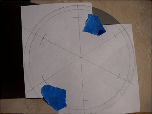
This shows how I laid out the plastic wheels, which will act as guards
keeping the magnets from flying off the iron wheel. With such a small
mill, this is unlikely, still, it never hurts to think ahead a bit. First, I used
my 2nd favorite tool (my compass) to lay out where the 6 magnet holes
should be placed. I taped my template to each wheel and marked the
centers with a punch. Easy Pete; my 1st favorite tool is my lathe!!
I should mention here that the way "I" am building this contraption does not conform with the standard build. For instance, these plastic wheels. Nobody else does this, but I was trying to get my head around how the magnets stay in their respective places, being attracted to their opposite face just across the air gap housing the stator as well as the iron plate they're attached to as a "flux-return" path, not to mention centripital force as they spin and just couldn't grasp the idea, so I came up with this little method of trapping them in a plastic "cage" the same thickness as the magnets themselves.
This method of mounting the magnets will also make it look less dangerous (to me at least) when things are whirring past the stator. The "regular" method makes it look like a saw blade to me, so I decided to be different, that's all.
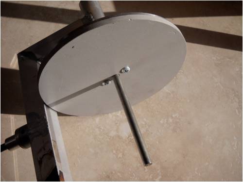
Here's a virgin plastic wheel mounted to the iron plate and each mounted
to the shaft of the windmill using a set screw.
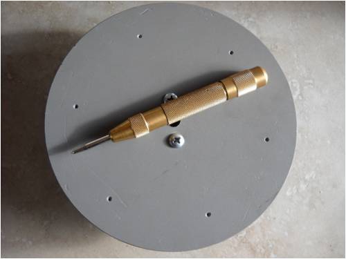
This shows the punch I used to mark the holes in their proper places,
each on one of the 6 lines I drew on using my compass.
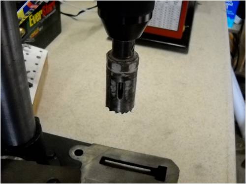
This 1" hole saw actually cut the holes too large, but it was the best I
could do. I used my drill press to carve out the holes.
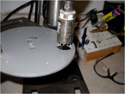
This shows one hole cut; 11 more to go.
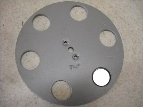
Here's all 6 holes cut in one plate with one 1" neo-magnet inserted
as things lie on my workbench.
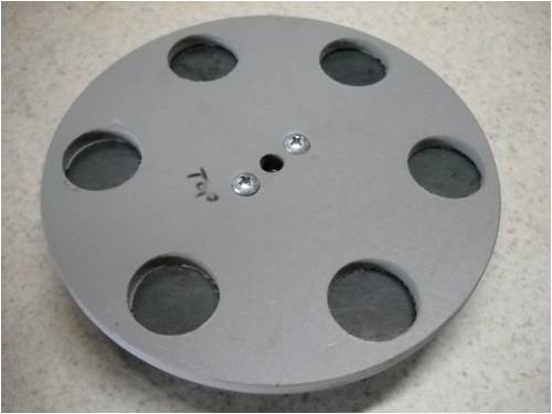
This is one plastic plate mounted to its iron plate awaiting magnet
placement.
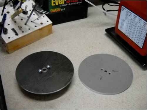
I threw in this shot to remind everyone that if you build stuff, then
take it apart to work on it, you must mark sides and positions, so
when it goes back together, everything is in the right spot.
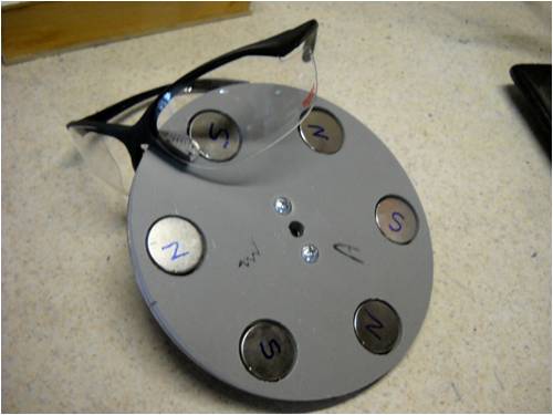
I'm showing my shooting glasses (safety glasses) here to emphasize
that working with neo-magnets is DANGEROUS. If they snap together,
they can splinter and send shards clean through your eye! Wear
safety goggles for crying out loud!
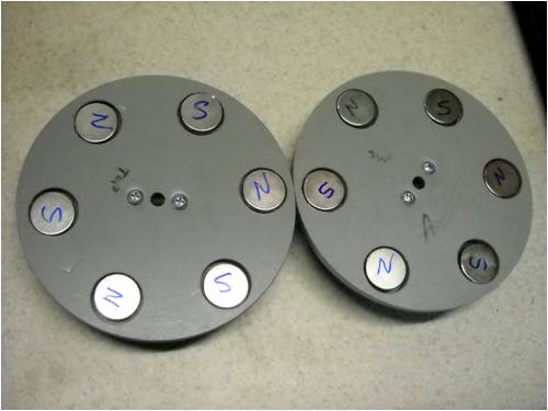
Here are both little wheels with magnets loaded. I have to remove
them tomorrow and put a drop of epoxy glue under each one, but I
stuck things together this evening for a "Kodak Moment". I hope I
can get things apart in the morning!
Before I mount these puppies on the shaft, I have to cut some sort of seperator to keep the two wheels from slamming together and locking up all the N-S magnets. If that were to happen, it'd likely take something on the order of an act of God to get them apart again. These little magnets, even though they are small to look at, are EXTREMELY strong. They'll pinch your fingers harder than a crab claw! Note how I labeled each with a "N" or a "S". That is so I can line things up when I finally anchor the wheels to the windmill's shaft, one wheel each side of the stationary stator in the center.
That's all for now; thanks for watching.
. . . . . MacEdited by MacGyver 2010-06-21
Nothing difficult is ever easy!
Perhaps better stated in the words of Morgan Freeman,
"Where there is no struggle, there is no progress!"
Copeville, Texas |
| |
paul_mac1

Regular Member

Joined: 17/05/2010
Location: AustraliaPosts: 74 |
| Posted: 08:13am 20 Jun 2010 |
 Copy link to clipboard Copy link to clipboard |
 Print this post |
|
Looking Bloody Good Mac!! |
| |
MacGyver

Guru

Joined: 12/05/2009
Location: United StatesPosts: 1329 |
| Posted: 07:00pm 20 Jun 2010 |
 Copy link to clipboard Copy link to clipboard |
 Print this post |
|
Morning After Pics
"Morning has bro .. .. .. ken; like the first mo .. .. .. o .. .. .. or .. .. .. ning". Remember that guy, Cat Stevens?
Anyway, it's Sunday morning here and I pushed the two magnet wheels together after first fashioning a small aluminum spacer thingy (with a set screw, but now I don't know what I was thinking nor why I took the time to do that set-screw part) so they wouldn't get permanently stuck together and here's what it looks like:
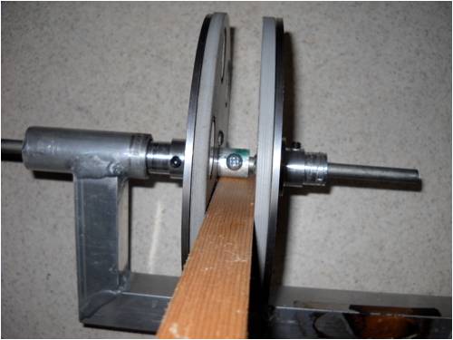
The cautious side of me said, "Put something stiff but kinda soft between
things before these two things get out of hand as they get closer and
closer to each other." I chose a 1 x 3 pine board. No Pete; don't add
any commentary!
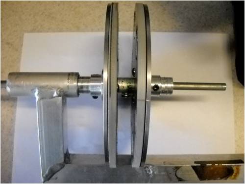
Here they are side by side. Turns out they are so strongly attracted to
each other, the shaft set screws are likely over-kill.
That's all for now. Next is the 9-coil stator build. I'll be hanged if I'm going to invest in several spools of copper wire until I find the right size wire and number of turns to make this puppy work, so I'll be dumpster diving for a week or two trying to capture some old a.c. dishwasher motors that I can dismantle and rob the wire out of.
Until then, enjoy the rest of the 4m and I'll be back at it as soon as I come up for air!
Edit: Oh, almost forgot. I didn't do the drop-of-epoxy-under-each-magnet part. The magnets are SO stuck, I can't imagine they'll move at all. At any rate, here's hoping.
. . . . . . MacEdited by MacGyver 2010-06-22
Nothing difficult is ever easy!
Perhaps better stated in the words of Morgan Freeman,
"Where there is no struggle, there is no progress!"
Copeville, Texas |
| |
oztules

Guru

Joined: 26/07/2007
Location: AustraliaPosts: 1686 |
| Posted: 03:30am 21 Jun 2010 |
 Copy link to clipboard Copy link to clipboard |
 Print this post |
|
....... 9 coils for 6 magnets....... did you do the geometry on this first?
If you go ahead with this, make sure you can remove the magnets. I suspect it will work with 6 per disk... In the N-S-N-S-N-S you have currently, you will have only 6 poles.
The output should be about half the normal axial, as you only have 1/2 the magnet mass I guess, and you don't have an opposing pole moving over the same coil, as you would in a normal 12:9 arrangement, so you miss out on half the voltage in each coil.
In the normal version, as the N cuts the left leg of a coil and generates an EMF, the S will cut the other leg of the same coil and induce an EMF of opposite sign, giving double the EMF that you will get per coil. Do you see it now?
Thats why we use 3:4 ratio for the 3 phase AXFX
..........oztules
EDIT: The magnets look lonely in the current configuration, but will look crowded if you add the other 6 per disk. The crowded one will still work pretty well, but ideally 1/2 magnet width is as close as we want to get from magnet to magnet if we want a decent airgap.
If you narrow the airgap a little, it will allow for closer magnet spacing with out too much inter magnet leakage.....but you start to suffer winding space loss.... it's a balancing act.
Try to get 12 per plate if you can.
Idle thought:
It should still work well if you make 1 plate all N-N-N-N-N-N and the other all S-S-S-S-S-S. This will give you 6 phantom poles for a 12 pole total using 6 magnets/disk as you currently have.
I have not tried this, but would be interested to see if there was any gain by doing this, rather than the N-S-N-S-N-S you have now.
Just a thought
Edited by oztules 2010-06-22
Village idiot...or... just another hack out of his depth |
| |
MacGyver

Guru

Joined: 12/05/2009
Location: United StatesPosts: 1329 |
| Posted: 03:49am 21 Jun 2010 |
 Copy link to clipboard Copy link to clipboard |
 Print this post |
|
Aaargh!
Color me stupid, but I actually counted the (9) coils and what I thought were 6 pairs (12 each) of magnets in that little gif you sent along. So, given that much information, I went ahead and built it like I did in the pictures I've posted.
I also did some monkeying around with my compass and made a template with 9 places to mount the (little) coils, so, yes, I actually did do my homework on this (I thought!).
If it's wrong, it's wrong. It's too expensive to use as a fishing weight, so it'll just have to light half a light bulb or something, I guess.
Like I've said elsewhere here, if it don't work, it'll make a dandy story to tell. I'm one of those simpletons who sees the light at the end of the tunnel and smiles, thinking it's the other side and not even thinking for one moment that it might be a train coming! 
Edit: Okay . . . . well, I've just been informed by PM that I blew it. If this thing works as all it'll be a miracle, so for those watching, maybe wait till it's all done before following my lead, eh?
Please excuse me for a moment while I go pound my head against the wall! Just kidding; I wouldn't do that for any reason I can think of, really. 
. . . . . Mac Edited by MacGyver 2010-06-22
Nothing difficult is ever easy!
Perhaps better stated in the words of Morgan Freeman,
"Where there is no struggle, there is no progress!"
Copeville, Texas |
| |
MacGyver

Guru

Joined: 12/05/2009
Location: United StatesPosts: 1329 |
| Posted: 04:08am 21 Jun 2010 |
 Copy link to clipboard Copy link to clipboard |
 Print this post |
|
[Quote=oztules]Idle thought:
It should still work well if you make 1 plate all N-N-N-N-N-N and the other all S-S-S-S-S-S.
And who would like to volunteer to pry all those magnets off the thing? 
Nah, I think I'll go with what I've built and if it doesn't do squat, then I'll rip it apart and do the all north opposite all south thing.
Suddenly, I'm really looking forward to building one of my "experimental" models. At least doing that I will be going into it virtually knowing it likely won't work and won't be disappointed having had the illusion it will work only to find out it doesn't.
Hey! Look at the bright side. The "test" mill I have up in the back yard, the one with the open blade tips, is still flying and we've had some 10 to 15 mph wind lately. It hasn't flown apart yet! I like Pete's (I think) signature: "Sometimes it just works".
. . . . . Mac
Nothing difficult is ever easy!
Perhaps better stated in the words of Morgan Freeman,
"Where there is no struggle, there is no progress!"
Copeville, Texas |
| |
oztules

Guru

Joined: 26/07/2007
Location: AustraliaPosts: 1686 |
| Posted: 07:25am 21 Jun 2010 |
 Copy link to clipboard Copy link to clipboard |
 Print this post |
|
It will still be a good little alternator..... just the coils will need to be twice as many turns as they would have been if you had 12 mags/disk.
With your little blades, it may still be way to powerful for it even with 6 mags/disk, you may actually get a better match  with the higher resistance stator at lower power levels. with the higher resistance stator at lower power levels.
If it is still to powerful for the blades, you can at least open the air gap up till you find the best match.
.............oztules
Village idiot...or... just another hack out of his depth |
| |
oztules

Guru

Joined: 26/07/2007
Location: AustraliaPosts: 1686 |
| Posted: 07:59am 22 Jun 2010 |
 Copy link to clipboard Copy link to clipboard |
 Print this post |
|
Above I said:
[quote]In the normal version, as the N cuts the left leg of a coil and generates an EMF, the S will cut the other leg of the same coil and induce an EMF of opposite sign, giving double the EMF that you will get per coil. Do you see it now? [/quote]
A correction is in order.
This is not quite how it works, and should be clarified. The net result is the same, but it is not from generating an opposite sign, it is from having an EMF of the same sign in opposite legs adding...... sometimes it pays to read what you write..
Sorry for that.
............oztules 
Village idiot...or... just another hack out of his depth |
| |
MacGyver

Guru

Joined: 12/05/2009
Location: United StatesPosts: 1329 |
| Posted: 03:58am 02 Jul 2010 |
 Copy link to clipboard Copy link to clipboard |
 Print this post |
|
Update July 1, 2010
There's been a slight change in plans. Because of my limited machining capabilities, I chose to use an "off-the-shelf" die-cut piece of iron plate as my magnet-backing plate. Unfortunately, in a "perfect world" it should have been about 1/8th inch larger in diameter, but I think it will work just the same.
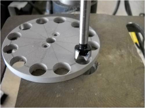
I drilled 1/2" holes in the sheet of HDPE plastic using a "Forstner" bit.
These holes hold the individual magnets and the sheet is almost the
same size as the magnets' thickness. It makes placing the magnets
way easy. All you do is choose the correct face alignment and slide
each magnet across the plastic until it snaps into the hole in the
plastic sheet, which is mounted to the iron magnet-backing plate.
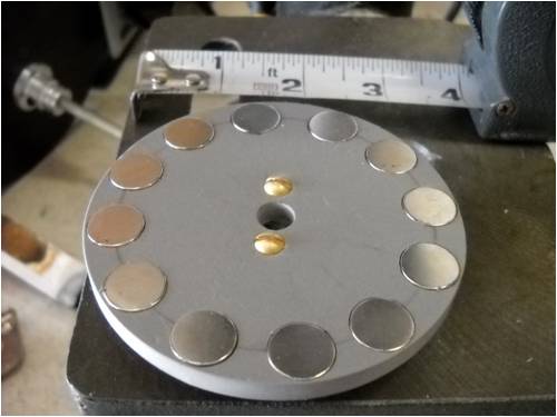
Next, I loaded each of 12 individual rare-earth magnets into the holes,
alternating the faces N-S-N etc. all the way around the circle.
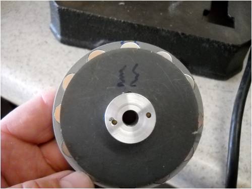
Here's a shot from the back side of one magnet wheel. Note the edges
of the magnets stick over the side of the iron plate just a little. Oil well,
can't win 'em all, I guess. I'm sure it will work just the same.
As soon as my latest order of magnets arrives, I'll place the other 12 magnets into the other wheel and mount things into the running gear of the windmill. All that'll be left to do (more or less) is to manufacture the stator using 9 coils of wire, placed equally about the circumference of the wheels. The stator will be mounted between each of the magnet-holding wheels, bolted to the frame of the windmill so the magnet wheels can rotate freely about it on each side. As the concentrated flux areas between each N-S or S-N pair of magnets passes over the wires in the stator, a voltage as well as a current will be induced into each. The stator will have three sets of 3 coils (each wired in series to form one set), which will allow it to produce 3-phase a.c.
I'll be back with more when it happens. Until then, the stuff I posted using 6 magnets on each disk is all good, except for the fact that I botched up, misunderstanding there are actually 12 magnets instead of 6, but the basics are all good. Might be a good thing to review the entire thread, if you're new to all this. Heck, it might do me good to do the same! 
. . . . . Mac
Nothing difficult is ever easy!
Perhaps better stated in the words of Morgan Freeman,
"Where there is no struggle, there is no progress!"
Copeville, Texas |
| |
| |
  Page 3 of 6 Page 3 of 6   |

