|

|
Forum Index : Electronics : Variable bench power supply circuit
| Author | Message | ||||
bfgstew Newbie Joined: 27/04/2013 Location: United KingdomPosts: 19 |
I had my suspicions Pete, but thought you may like to keep your anonymity..... 
I do like to take my time on these things, mainly due to getting all the bits together and having the time to make it, I generally have little spare time when away from work and only get to do most of my project work at work during quite periods....... 
I may have another problem, I inadvertently shorted Vc (pin 11) and Vout (pin 10)together, and now it doesn't give any output and I have left my spare LM723 at work, I know these are tough little buggers, but have I killed it? Red to red, black to black and blue to bits! |
||||
Downwind Guru Joined: 09/09/2009 Location: AustraliaPosts: 2333 |
I cant answer that, although check for any shorts across ALL (139 and 3055) transistor pins before you plug a new chip in, (remove the old chip before testing) Yes i tend to stay anonymous on some forums, but this one im just myself. Pete. Sometimes it just works |
||||
bfgstew Newbie Joined: 27/04/2013 Location: United KingdomPosts: 19 |
Hi again Pete, sorry to bug you again. Well it looks like I did kill the LM723, I found my spare one, popped that in after I checked everything and it works again. I am still having problems though getting above 20V max output, and min output is 2.8V and not 0V. I did change R9 to 120R but that has made no difference. I checked voltages on the base, collector and emitter of the BD139 - At Min output B = 19.0V E = 18.4V C = 38.1V At Max output B = 36.2V E = 35.4V C = 37.7V Any ideas? Red to red, black to black and blue to bits! |
||||
Downwind Guru Joined: 09/09/2009 Location: AustraliaPosts: 2333 |
I told you the wrong resistor to adjust the value of, its not R9, its R8 or R7. R7 and R8 form a voltage divider to set a reference voltage on the inverting input, it is here you change R8 to allow a higher output voltage, by increasing the value of R8 should decrease the voltage to pin 4 the inverting input. Pin 5 is the non-inverting input that the voltage adjusting pot is connected to and where a output voltage is set, when the voltage on pin 4 (inverting input) is higher than the voltage on pin 5 (non-inverting input) it switches the output (pin 10) low, turning the transistors off, which then drops the voltage on pin 4 and pin 10 switches back on again, that is how the regulator works to control the voltage. By increasing R8 means the voltage from the transistors will need to be higher before pin 4 voltage exceeds pin 5 voltage, which effectively increases the the volts output of the circuit, but this will also increase the minimum voltage that can be set by pin 5, so the minimum output voltage will increase above the 2 volts you currently have. Short story is try changing R8, and it should increase or decrease the maximum output voltage. Pete. Sometimes it just works |
||||
bfgstew Newbie Joined: 27/04/2013 Location: United KingdomPosts: 19 |
Thanks Pete, I do appreciate your time and effort helping me, I now have a better understanding of the workings of the LM723 and the circuit, I spent a good many hours reading up on it, so I shall finish this little project off as it is for now, I am happy with the 2V min output, OK would like max to be 24V+ but I am not going to complain or bug you with why, why, why. I shall work it out myself and hopefully learn a little more on the way. Once again, thanks Pete, and The Backshed guys. Stewart Red to red, black to black and blue to bits! |
||||
bfgstew Newbie Joined: 27/04/2013 Location: United KingdomPosts: 19 |
Ha Ha, we have a result..............26.8V output. The reason for not reaching it was down to the fact I had the gate and emitters wired the wrong way on the 2N3055's, what an idiot, I was blaming everything and everybody for this not working and in the end it was down to me making a careless mistake, even though I colour coded the wires so I didn't get them wrong, I still did..................DOH!!!!!!!!!!! Now to pop it into an enclosure, add a few LCD displays for Amps and Volts, also going to add a cooling fan, may have that running off a temp sensor, not sure yet. Any how, a big thanks to Pete for his support, much appreciated. Stewart Red to red, black to black and blue to bits! |
||||
| greybeard Senior Member Joined: 04/01/2010 Location: AustraliaPosts: 161 |
errh, not sure that you'd find a 'gate' connection on a bipolar transistor |
||||
bfgstew Newbie Joined: 27/04/2013 Location: United KingdomPosts: 19 |
Sorry I meant base, thanks for correcting me...............  Red to red, black to black and blue to bits! |
||||
| irishron40 Senior Member Joined: 22/09/2014 Location: IrelandPosts: 251 |
hi i ordered a few lm723 . but received them with different code. are they the same as lm723? the last four digits on mne are 8543 ( would this be a batch number? cheers ron |
||||
| Gizmo Admin Group Joined: 05/06/2004 Location: AustraliaPosts: 5078 |
Without looking for the correct answer, I would say yes, they are 723's Glenn The best time to plant a tree was twenty years ago, the second best time is right now. JAQ |
||||
| irishron40 Senior Member Joined: 22/09/2014 Location: IrelandPosts: 251 |
thx Glenn, I am gonna build downwinds powersupply based on a lm 723 |
||||
VK6MRG Guru Joined: 08/06/2011 Location: AustraliaPosts: 347 |
The last 4 digits on the bottom the the chip are the date code. 29th week 1984. The date code on the chip you have is 43rd week 1985. Have a look here at the wiki on semiconductors for an explanation here. https://en.wikipedia.org/wiki/Semiconductor_package Hope this helps. Its easier to ask forgiveness than to seek permission! ............VK6MRG.............VK3MGR............ |
||||
| irishron40 Senior Member Joined: 22/09/2014 Location: IrelandPosts: 251 |
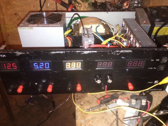
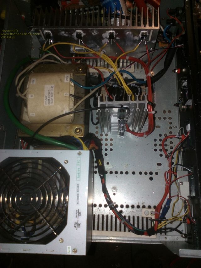
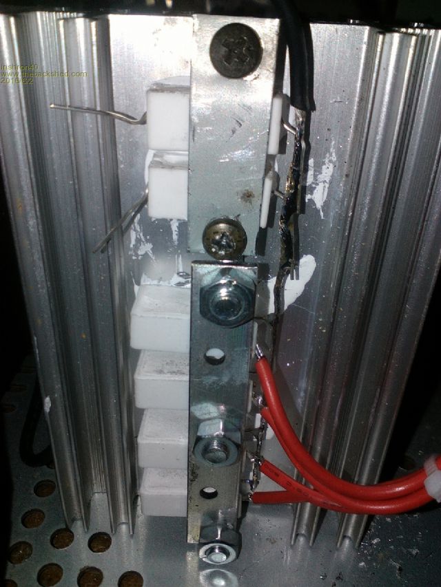
Hi All. I mend to start this project last year , but due to having 2 strokes and become diabetic everything has been on hold for a while. i decided to build pete`s power supply based on this lm723 I also decided to put in a separate 15A psu power supply so I can run things independent. I have mounted all my 5W 0.1 ohm and 5 W 0.47 Ohm resistors on a heatsink. also the 4 tip41C transistors are mounted on a very large heatsink as this was available to me. ( better to big then too small) Still in progress, but just liked to share this ron 


|
||||
| irishron40 Senior Member Joined: 22/09/2014 Location: IrelandPosts: 251 |
hi. just wonder how much can the current be limited to with this power supply? would it be possible to limited the supply to Milliamp if needed? thx, ron |
||||