
|

|
Forum Index : Windmills : dual f and p mill questions
| Author | Message | ||||
| KarlJ Guru Joined: 19/05/2008 Location: AustraliaPosts: 1178 |
Sorry for the long reply I have considered it / Phill carefully. You've only got to look through Phill's failures to see that it isn't all beer and skittles, he takes it on the chin and improves, the question is do you have the same amount of time and patience. Phill has done lots of R&D (of which we / the forum have benefited greatly - CAP testing, AXFX, furling etc) There is lots of work in the blade hub but you have that sorted -the next bit For my 2c -I'd be asking Phill how much for the turbine mount and tail assemblies, the knowledge that it will work and not rip itself apart is worth every cent. There will be no love lost and no-one will think any less of you for going a tried and true solution. For me it was a simple decision to go with Phills mill. Everything is adjustable, hence I can still play with it, I can fix it, paint it, play with different stator combos and wiring not to mention building all the other bits. In short -the turbine head from Phill represents less than 20% of the final cost -in reality its cheap piece of mind. Phill even test flew mine before I took delivery to make sure it was 100% spot on, it only takes a few degrees here and there to make what was otherwise a good machine perform poorly, simple stuff like the tail kicker required more than a few tweaks, cuts and shuts so that the desired result was obtained, as a result he gets usable power where other mills in the same class get nothing just weathercocking about OZ, Gordon, Phill, etc the knowledge base of the forum weren't born yesterday and will help you with guidelines -in fact they did with Phills, it worked to a degree and he tweaked and tweaked until it was a good as it could be. from start to finsh of his design the power output (over the course of a day) has more than doubled 750W max with 48V+ power available from 9km/hr wind. 1200W max with power available from 15km/hr wind. almost beating the quad stator mill! the fact that the dual matches the AXFX to 20km/hr is a triumph! (the AXFX has voltage triplers too the f&p doesnt). We like the blade hub and the enthusiasm you show, Bite the bullet and give him a call save yourself alot of heartache, pain and failures. Spend the effort and sleepless nights considering and building the other bits like tower, wiring, capdoublers etc etc etc etc etc Luck favours the well prepared |
||||
| gpalterpower Senior Member Joined: 19/07/2009 Location: AustraliaPosts: 175 |
Thanks for your concern.much appreciated Time and patience.2 very important requirements when making a mill. Patient....I am . Time...... well thats another thing. We've been kinda busy for some months now at work, and thats where the patience comes in. As much as I would like to get stuck in to this project I am happy to chip away when I can, with a little help from you guys if you dont mind. I get a real kick out of fabricating things. If I can see and understand it I can usually make it. However,as you say , Phill has done a lot of R&D and I still would be interested in what he has to offer...it could save me some headaches. Marcus if it aint broke dont fix it!! |
||||
| GOFJ Newbie Joined: 22/12/2009 Location: AustraliaPosts: 27 |
On the subject of furling, I was looking at the ExMork (Chinese) wind generator. It uses a pivoting tail fin rather than tail boom so there are no impacts of the tail boom hitting the stops but the thing that I noticed was the fan was quite some distance out from the mast pivot. This will give the wind thrust for furling a greater torque as the fan comes around to partially balance the reducing thrust from the lesser frontal area. Whether this is technically better than the pivoting tail boom I am not too sure but it looks like if your fan is too far in front of the mast the furling in gusty conditions will test the welds on the tail boom stop (for a pivoting tail boom) Jack |
||||
| KarlJ Guru Joined: 19/05/2008 Location: AustraliaPosts: 1178 |
further out the blades from the pivot, the greater the moment arm, hence once its going (ie turning out of the wind), its harder to hold it into the wind. This is a handy way of keeping the mill's c of g over the tower as the offset can be less. I guess once you satrt talking hundreds of kilos, this becomes a factor. In our case the 25KG of blades and generator offset 100mm is going to make very little difference and the furling characteristics are well documented -thus simpler. Luck favours the well prepared |
||||
| gpalterpower Senior Member Joined: 19/07/2009 Location: AustraliaPosts: 175 |
Jack I had a look at the exmork site and i see what you mean. That fan sticks out a fair way from the mast pivot. Is it possible that it is not nesessary for the fan to have any offset, but furling is done by the tail fin alone. I had an idea to prevent the tail from hitting the stops too hard. It may be possible to incorporate some sort of mechanism to slow down the return, say with a steering dampener off a motor cycle or a screen door closing shocky.....something along those lines. Karl, Saw the pics of your mill. Should be proud of your work. Looks fantastic and inspires me to get a kick a long with mine. Marcus if it aint broke dont fix it!! |
||||
| KarlJ Guru Joined: 19/05/2008 Location: AustraliaPosts: 1178 |
NO must always have some offset otherwise there is no trigger to start a yew of the turbine out of the wind. Things to think about -what does the furling tail do? Does it hold the turbine into the wind Does it hold the turbine out of the wind. Answer is not what most people think, of course it holds the turbine into the wind to counterbalance the offset of the turbine. With having only a little offset like the EXMORK, the tail has less moment to beat -relative to the size of the machine. That said, the generator (on the EX)is Huge and I would say the Pics dont do it justice, there is still 100mm+ offest there. Keep in mind if an Exmork gets out of control during factory testing, they just get another one. If yours were to have a similar demise during testing, like Phills! then you must be prepared for that. Start at decent offset and work back, plenty of articles on otherpower about windseeking of big mills, and the result -total destruction. The general consensus there now is set them up to furl at 20MpH, if it works you can play with it a little, if it didnt work too well and it furls at 30mph thats ok and it wont destroy itself. Luck favours the well prepared |
||||
| gpalterpower Senior Member Joined: 19/07/2009 Location: AustraliaPosts: 175 |
Thanks Karl,.......again, Just trying for an easy way out....again!! 
I am slowly beginning to understand how these mills furl. More to it than I thought. Back to the drawing board! regards Marcus if it aint broke dont fix it!! |
||||
| gpalterpower Senior Member Joined: 19/07/2009 Location: AustraliaPosts: 175 |
Well Ive been away for a while but now im finally going to finish the dual mill I started years ago. Ive used most of the original parts I manafactured and made a few changes but nothing is set in concrete yet as the whole thing is just tack welded together.The first pic is an attachment that sits ontop of the tower. It houses a 40 mm thick walled hollow shaft suported by 2 6008 bearings. The nacel sits upon this. 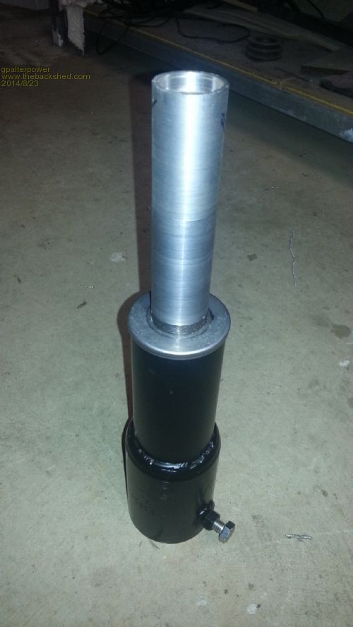
It is made up from the following parts The bearing mounted tube is secured on the base by a circlip which holds everything from falling apart when hoisting the mill in the air. 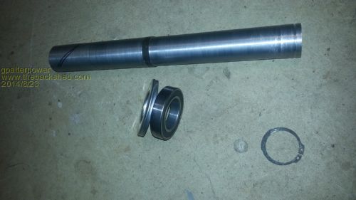
The nacel is the heart when it comes to fuling so I believe its critical in dimentions. I made the distance from the tower shaft and the turbine shaft 100mm which is tilted up at angle of 5 degrees. Not too sure if these are correct or within tolerances, but im going on previous posts and pics. Any input to this would be greatly appreciated 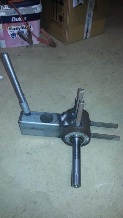
And with it assembled. The 2 sets of 13mm rhs poking out are for a cowling that im going to fit later on to protect all electrical components. 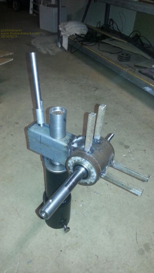
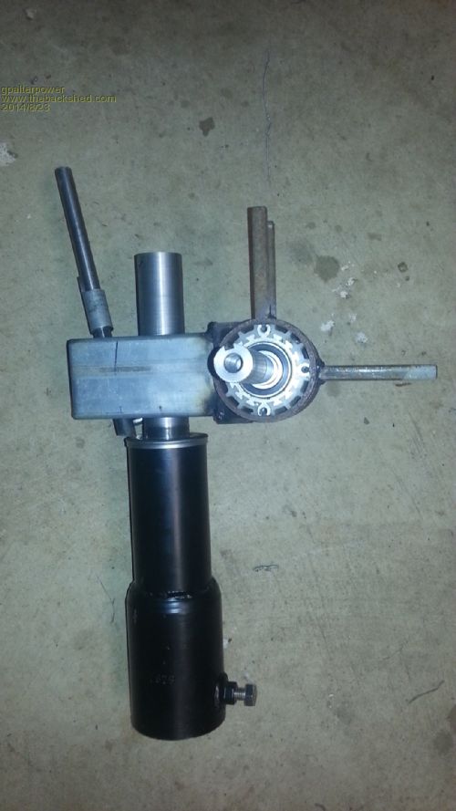
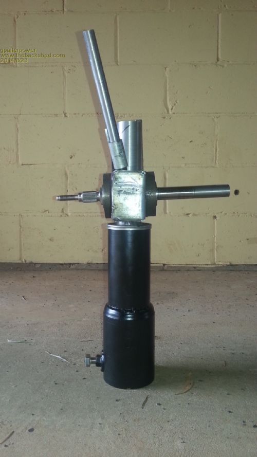
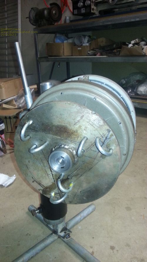
The rear flywheel is attached in the normal manner. The front is a little different. I machined a section away and fabricated a ferrule to slip over and tighten to secure to the shaft. The blade hub also sits hard up against the ferrule. 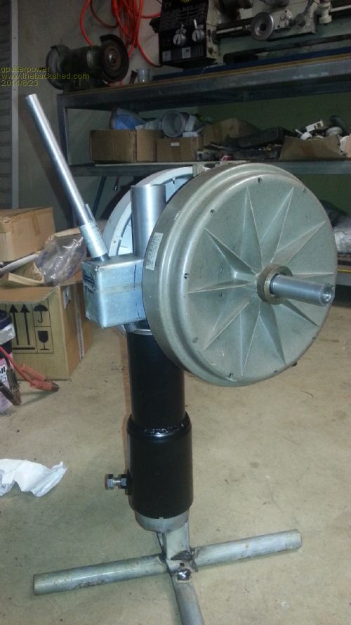
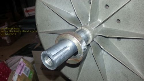
And with the blade hub attached. A 6mm key and 12mm bolt in the front of the shaft to drive the mill. 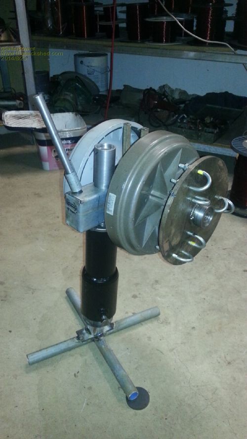
This is the hinge that sits upon the first length of 75mm pipe which is concreted in the ground . the second length slips thru and pivots the mill to about 8.5 metres in the air. The four half chain links are for the guy wires 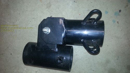
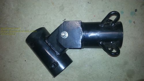
if it aint broke dont fix it!! |
||||
| brucedownunder2 Guru Joined: 14/09/2005 Location: AustraliaPosts: 1548 |
Hi Marcus. Nice work mate . You must have gone to the same tech college as Phill,lol. first ,why are the "U" bolts not in line ? second, I like the fabrication , cover the rotors, they don't like UV. Yep, I know you know this,lol. I made a dual , still have it ,one day will put it together again ,along with the LG stuff I've got waiting ---- my workshop is like a doctors waiting room --next please !!. Bruce Bushboy |
||||
| Jarbar Senior Member Joined: 03/02/2008 Location: AustraliaPosts: 224 |
Bruce, I think the idea is for the blade shafts to pass the generator axis which transfers the the blade torque and clamping load across the whole plate instead of just the edges.I have incorporated this on some of my designs as yet unfinished.I think I've been out of action for a similar period unfortunately.I agree he has made an excellent nacelle assembly. 
Anthony. "Creativity is detirmined by the way you hold your tounge".My Father "Your generation will have to correct the problems made by mine".My Grandfather. |
||||
fillm Guru Joined: 10/02/2007 Location: AustraliaPosts: 730 |
Hi Marcus , Looking like a nice build so far but I think I have seen that bearing housing and frt rotor idea some where before. 
Anyway you seem to be getting back into the swing of things but still have a way to go . I personally do not like configuring blades that way as the centrifugal force now acts as a giant lever on the outer clamp and when the blades gets going in a good breeze its to easy for everything to go pear shaped. Hey but just get it in the Air and fix things when and if they break. Keep us posted , it is just good to see someone doing something !!!  PhillM ...Oz Wind Engineering..Wind Turbine Kits 500W - 5000W ~ F&P Dual Kits ~ GOE222Blades- Voltage Control Parts ------- Tower kits |
||||
| gpalterpower Senior Member Joined: 19/07/2009 Location: AustraliaPosts: 175 |
Morning all and thanks for the comments. When I first made the hub I only had acces to a fairly small lathe and the maximum dia I could turn was 250mm. So I had to think of a way to somehow fit 3 shafts on to that plate. A cross hatching idea was the best I could think of which is why it looks like the "U" bolts dont line up.I did not think outside the square when it comes to pivoting on the outer clamp. There may well be issues down the track and I allready have some plans in the back of my mind how Ill make the next one, but for now ill run with what I have. There could also be an issue with using the original shaft driving 2 rotors as well as the hub. A lot of twisting forces on that 25mm shaft. hope it holds. The pic from my earlier post below shows the shaft configuation. regards Marcus  if it aint broke dont fix it!! |
||||
| Tinker Guru Joined: 07/11/2007 Location: AustraliaPosts: 1904 |
That giant lever you are talking about only springs into action if the hub should suddenly offer a much bigger resistance against rotation (seizing up). I doubt there is any significant different centrifugal torque load acting on the outer u-bolt with that arrangement under normal power generation loads than if the blade shafts were arranged in the more conventional way. We are talking here of RPM < 600 I assume. What will be different is the airflow across the blade which is now more obliquely but again not, IMO, enough to effect their efficiency significantly. Klaus |
||||
fillm Guru Joined: 10/02/2007 Location: AustraliaPosts: 730 |
Tinker, I think you are on the wrong track, if the blade outer clamp was removed and the inner clamp could pivot freely then the weight mass would want to swing out until it is at its balance point radiating out from the center, this would still the same for driving an alternator, and yes you are correct here, seizing & braking would amplify this load. The leverage force ratio on the outer clamp would basically and very roughly be the distance between clamp x distance to center of the mass of weight in the blade but I am sure it will much more complex than that in a true mathematical equasion . As it rotates the outer clamp takes this load factor and I would think at 600RPM if the blade tube if it not strong, then would want to start bending if not already. I would think the original intention was with only small light blade & hubs being able to have well spaced clamps to hold the blades . Airflow or blade performance should not affected as the blade is still at the same AOA and faces the wind as it should 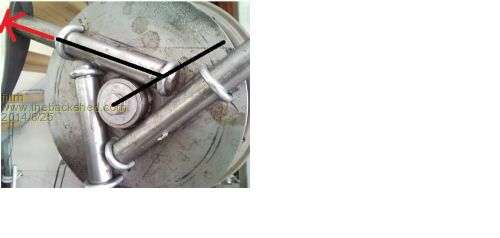 PhillM ...Oz Wind Engineering..Wind Turbine Kits 500W - 5000W ~ F&P Dual Kits ~ GOE222Blades- Voltage Control Parts ------- Tower kits |
||||
| Jarbar Senior Member Joined: 03/02/2008 Location: AustraliaPosts: 224 |
This type of bending moment already exists with the blade sections design.When it was originally conceived it was drawn up by Glenn(Gizmo)with the shaft to be located thru the center line of the blade chord,but this presented a problem of not enough space to fit an adequate shaft diameter. I suggested that it be moved to the widest depth section of the of the blade,closer to the leading edge.Which at the time looked a bit odd and did throw up the question about unequal mass around the shaft.(Although the hollow extrusion is comparatively light)As it stands about three quarters of the blade mass is in the trailing edge section.This may have become more pronounced with the blade material going from PVC to Aluminum although I'm not sure about the per meter weight of the Aluminum blades? But either way the fact is the blades themselves are already offset and with the above attachment configuration might actually compensate somewhat for the off center blade mass.If the blades were orientated to the above photo for an anti clockwise rotation the offset mass of the blade could be said to be counterbalancing the effects of the leverage being suggested. In fact every mill that's been produced with these blades has the same bending moments to the shafts attachment point.To what degree one is greater than the other,that really is a mathematical can of worms.  I have just noticed the blade on the shaft on left side of photo,which would be adding to the leverage,but like Tinker I would wonder if it's enough to cause shaft bending. I have just noticed the blade on the shaft on left side of photo,which would be adding to the leverage,but like Tinker I would wonder if it's enough to cause shaft bending. 
Anthony "Creativity is detirmined by the way you hold your tounge".My Father "Your generation will have to correct the problems made by mine".My Grandfather. |
||||
| Tinker Guru Joined: 07/11/2007 Location: AustraliaPosts: 1904 |
Fillm,I very much doubt that a windmill blade attached only by a pivoting inner clamp would indeed balance by pointing out directly radially from the shaft center. To do that one has to completely ignore the wind effect on the blade. As well as the blade's longitudinal axis balance as Jarbar so succinctly pointed out. Since with a windmill the blade is driving the shaft I think the blade would assume a forward raking (blade tip radially ahead) balancing point. This would nicely complement the off center shaft in the blade IMO. It would be interesting to test that but one needs access to a high speed camera etc. Klaus |
||||
| brucedownunder2 Guru Joined: 14/09/2005 Location: AustraliaPosts: 1548 |

This was my set-up for a dual some years back . The yellow rotor was fitted with Neo's. I think the red one was also , but during fitting I dropped it on the concrete driveway and swore a lot --that ended that project.,lol. But the neo's sure did give more power. That hub was an aluminium casting from Trev . Very heavy duty, trev makes excellant stuff. That's aircraft grade Al,tough as. Bruce Oh, sorry, the hub is not shown ,,I'll dig it up Bruce Bushboy |
||||
fillm Guru Joined: 10/02/2007 Location: AustraliaPosts: 730 |
Tinker, Think about the fact that the blade is driving the the blade hub through the shaft that is held buy the clamps with ability to drive forward using power from the wind, it does have drag but is overpowered by lift and if this was not the case it would not move forward.( take the back stay of your yacht with the sails up and what will happen) Then the blade hub is driving the alternator shaft which is opposing the forward movement with it Amp load. If the 3 blades were able to be pivoting on the inner point and interconnected they would more likely want to be on the opposite side at balanced position between centrifugal force and pulling the opposing load. Take the blades of the tubes and replace the outer clamp with springs and you then have a flyweight governor arrangement. So one would think the easiest fix is to have the blades set in anticlockwise rotation, it may help in some small degree but centrifugal forces will always be the greater force to deal with and it will still be acting on the outer clamp with this configuration. PhillM ...Oz Wind Engineering..Wind Turbine Kits 500W - 5000W ~ F&P Dual Kits ~ GOE222Blades- Voltage Control Parts ------- Tower kits |
||||
| Tinker Guru Joined: 07/11/2007 Location: AustraliaPosts: 1904 |
Fillm, I will digest your reply (deleted here) for a while but one comment above needs clarification. *you* are wrong with the removing the backstay example. My yacht does *not* have a backstay nor is the mast supported by any other stays. Its called a 'free standing rig', cat ketch in my case and she sails well despite the absence of any stays holding the mast up. 
I am familiar with the lift/drag effects of airfoils /sails and its not as simple as you put it. For example, a VAWT is a drag powered device and yes, it does rotate forward albeit nowhere near as efficiently as a foil that also has lift powering its rotation. This 'lifting force' BTW acts not exactly in the direction of rotation but is a vector between the angles of the drag and lift forces. Its the windmill shaft that forces the blade to rotate forward just as the keel/ centerboard of a yacht allows the boat to progress at an apparent angle to the wind. Sailing downwind is drag powered just like a VAWT unless somehow the water drag can be overcome (planing) and the increased speed causing the apparent wind to move forward so the sail is now experiencing lift. Its a fascinating subject... I think the radial/ off radial windmill blade mounting conundrum could only be resolved by fitting load cells on both sides of the inner and outer blade mounting. With that data and the calculated centrifugal force at a given RPM this discussion could be settled scientifically once and for all. A high speed camera (as I mentioned above) would, on second thought, not suffice as it is very likely the blades unbalance if not securely clamped in a fixed location with disastrous results. Klaus |
||||
fillm Guru Joined: 10/02/2007 Location: AustraliaPosts: 730 |
Tinker, I am well apt with sailing terminology having had a lot of experience on Yachts of all sizes and rigs from the age of 12 on, I still own a 21ft trailer yacht that does not see a lot of action these days sadly. No stays or stayed mast ketch, sloop whatever it still means, strength and correct design to deliver the power to the hull through stays , chain-plates or a sizable bulkhead etc. Stays or not, the principal of transmitting power from the sails efficiency to create lift high pressure moving to low pressure is still the same,with virtually the same principal applies to wind turbines. Anyway I think this thread has gone of track enough , and apologies to Gpower who might be in a bit of a spin about his blade hub design at present. If we want to delve into the pros and cons of "blade hub design" then it might be best to start another thread PhillM ...Oz Wind Engineering..Wind Turbine Kits 500W - 5000W ~ F&P Dual Kits ~ GOE222Blades- Voltage Control Parts ------- Tower kits |
||||