|

|
Forum Index : Microcontroller and PC projects : SSD1963 Board in Sprint Layout
| Author | Message | ||||
| phil99 Guru Joined: 11/02/2018 Location: AustraliaPosts: 2134 |
setpin GP26, AIN Change to:- battery = gp26 setpin GP26, AIN The trick is to differentiate between a pin number and the Pin() function which can contain either a GP number or a pin number.battery = pin(gp26) Not needed here but there are some places in MMBasic where the pin has to be an integer, so GP can't be used. that is where the MM.Info(pinno GPxx) function comes in handy. To make it easier you can define your pins with a constant at the start of a program. eg Const VinPin = MM.Info(GP26) then use SetPin VinPin, AIN Battery = Pin(VinPin) Print Battery . Edited 2024-09-22 17:12 by phil99 |
||||
Bryan1 Guru Joined: 22/02/2006 Location: AustraliaPosts: 1343 |
Thanks again Phill  that worked but I did have to change to float instead of integer to get past the decimal point and just ran the code tweaking the * number and got within .01 of a volt with quite a few readings. that worked but I did have to change to float instead of integer to get past the decimal point and just ran the code tweaking the * number and got within .01 of a volt with quite a few readings.So that's one hurdle out the way and alot more reading will be done so I can get better at coding. Regards Bryan |
||||
| Mixtel90 Guru Joined: 05/10/2019 Location: United KingdomPosts: 6765 |
The physical pin number thing is one of the few foibles of MMBasic. If you use the GPnn format for as much as possible you won't go far wrong as those numbers are what the chip itself uses. That means that it's far easier to run your code on a different board. The RP2350 ha thrown another curved ball. The B version has its ADC pins on GP40-GP47 whereas the A version has then on GP26-GP29. There's nothing like a bit of conformity. :) Mick Zilog Inside! nascom.info for Nascom & Gemini Preliminary MMBasic docs & my PCB designs |
||||
Bryan1 Guru Joined: 22/02/2006 Location: AustraliaPosts: 1343 |
Yes I can see a few jumpers been putting in on these PCB boards when they get here and this is a big learning curve for me. Like I should of known NOT to use GP8 for ADC where GP26 did work today. I'm sure the list will go on but eh it is fun trying to get back in the game. |
||||
Bryan1 Guru Joined: 22/02/2006 Location: AustraliaPosts: 1343 |
Well those 0V7670 camera modules and HC-SR04 distance sensors turned up today this project moves onto the next stage. With the SSD1963 taking most of the pins on the pico and the 0V7670 camera needing 13 pins the RP2040 Zero looks the goods for a new pcb to be made. So D0 to D13 are used and GP14 for SCL with GP15 for SDA. The pcb should be small enough to fit on the back of the camera and the zero just waiting for that command to take a picture and send it. The Distance sensor can connect to GP8 and GP9 and the 10K/4K7 level shifter can move to the sea of holes which leaves the GP8 to the BatVin pad can be used for GP8 so no track cuts there. Regards Bryan |
||||
Bryan1 Guru Joined: 22/02/2006 Location: AustraliaPosts: 1343 |
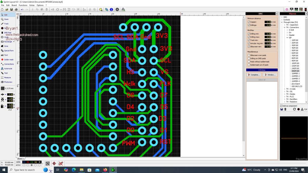
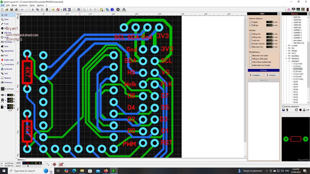
Ok just had to come down from the shed and get this PCB designed   The board measures 35x34mm and all tracks fitted easily on both sides, now as I2C will be new to me do I have it right where the SDA and SCL lines from the camera module are tied to the zero and the output I2C pins ? On the zero D0-D7 are the bit lines, GP9 is XLKpin, GP10 is PLKpin, GP11 is HSpin, GP12 is VSpin and GP13 is the resetpin. Now as GP8 was free it was connected to the WCLK pin on the camera so the camera registers can be tweaked. RP2040Camera.zip Regards Bryan Edited 2024-09-23 16:06 by Bryan1 |
||||
| Mixtel90 Guru Joined: 05/10/2019 Location: United KingdomPosts: 6765 |
When using I2C you have to provide pull-up resistors on both lines to 3V3. I would suggest using 4K7 for these. You only need them at one end. It's helpful if all devices are powered from the same 3V3 supply, however *officially* this isn't necessary. On the Pico we use 3V3 I2C wherever possible. The signal levels will often work with 5V I2C devices providing the pull up resistors are to 3V3 and not 5V. GP8 and GP9 are the pins usually used for attaching a PS2 keyboard to the Pico or a USB-TTL converter to connect a USB Pico to the console (as the USB connector can't be used for that when it's in Host mode). If you want to use them for anything else you will have to use OPTION KEYBOARD DISABLE and only use the console for configuration access. It's good practice (IMHO) to always reserve GP8 and GP9 if possible. You can use different pins if using a console, but you do need them on a hardware COM port. Mick Zilog Inside! nascom.info for Nascom & Gemini Preliminary MMBasic docs & my PCB designs |
||||
Bryan1 Guru Joined: 22/02/2006 Location: AustraliaPosts: 1343 |
Duly noted on the pullup's now I was going to put the pullup's on the sea of holes but found room beside the zero. For future I will keep that in mind about GP8 and GP9 but for this first LCD project no keyboard will be needed and with the next one I can put in a PS2 port now I know what those pins are for.  If you guy's reckon everything is right I'll get this board off to JLCPCB and I reckon with the credit I have there will pay for these boards. Regards Bryan |
||||
Bryan1 Guru Joined: 22/02/2006 Location: AustraliaPosts: 1343 |
G'Day Guy's, Got that camera board off to JLCPCB this morning and $4.62 for 5 boards  Now I have setup that RP2040 on the breakout board I got using Mick's design, so I setup a 20x4 lcd so when I get I2C going I can see whats going on on the zero. So yet another stumble after setting up DEVICE LCD INIT GP1, GP2, GP3, GP4, GP6, GP5 then trying DEVICE LCD 1, 2, "Sleeping" gives the result ERROR NOT OPEN So yesterday read the manual for hours trying to find the solution with no luck so just like with my SSD1963 setup the next day when I turned it on it just worked. But this zero didn't do the same.  Regards Bryan Edit: Just did a clear flash and reinstalled V6 the above steps just worked  So note to self if using a pico with options set before do a clear flash first to save hours of pain. So now onto getting I2C going and more fun on the way So note to self if using a pico with options set before do a clear flash first to save hours of pain. So now onto getting I2C going and more fun on the wayEdited 2024-09-25 09:37 by Bryan1 |
||||
Bryan1 Guru Joined: 22/02/2006 Location: AustraliaPosts: 1343 |
Nope no go as it just keeps saying NOT OPEN when I'm using the zero and keeps going the error GP0 to GP10 aren't inputs Even trying to do a DEVICE LCD in the terminal keeps saying NOT OPEN So time to leave this for a while and keep reading and researching, anyway found this for the 0V7670 camera and it is pretty neat how he uses a 74165 shift register to get the data from 8 bits to 2 bits for the I2c output. Now while googling this topic a youtube video did come where Peter Mather interfaced this camera in MMBasic. Edited 2024-09-25 15:37 by Bryan1 |
||||
Bryan1 Guru Joined: 22/02/2006 Location: AustraliaPosts: 1343 |
Well fresh start this morning, did a clear flash and put V6 back on as I did try V5.8 PicoMite MMBasic Version 6.00.00b4 Copyright 2011-2024 Geoff Graham Copyright 2016-2024 Peter Mather > DEVICE LCD INIT GP1, GP2, GP3, GP4, GP6, GP5 > DEVICE LCD 1,2, "Waiting for I2C" > C:\Bryan\camera zero slave.bas Uploading using: 'target port\COM12:38400 s\picomite Upload started NEW > AUTOSAVE Upload completed 1 Saved 295 bytes > Time taken: 1173mS RUN [4] Device lcd clear Error : Not open > Now the code I used SETPIN GP15, GP14, I2C2 device lcd clear 'also tried CLS device lcd 1, 4, "waiting for I2C input" I2C2 SLAVE OPEN &H50, tint, rint DO : LOOP SUB rint LOCAL count, a$ I2C2 SLAVE READ 10, a$, count device lcd clear device lcd 1, 2, LEFT$(a$, count) END SUB SUB tint LOCAL a$ = Time$ I2C2 SLAVE WRITE LEN(a$), a$ END SUB So this what I am having trouble with, my idea is to get I2C going using the example in the manual but the zero is failing to see the LCD |
||||
Bryan1 Guru Joined: 22/02/2006 Location: AustraliaPosts: 1343 |
Now to go on as I saw after the INIT line the LCD did print "Waiting for I2C" and after I tried the code tried to do a command line DEVICE LCD > device lcd 1, 2, Time$ Error : Not open > device lcd 1, 2, str$(time$) Error : Not open > So not sure why the zero is doing this as the DEVICE LCD INIT command has been done. |
||||
| phil99 Guru Joined: 11/02/2018 Location: AustraliaPosts: 2134 |
I don't have one of these displays so can't test. This I2C scanner program should locate your display. In your program the pins are the wrong way around and the Pico is the master. Slave mode is only used when connected to another master. 'Pico I2C2 detect program ' Set Pins! SetPin gp14, gp15, I2C2 ' Open first I2C2 I2C2 open 100, 200 'speed kHz, timeout mS ' Prep table Print " 0 1 2 3 4 5 6 7 8 9 A B C D E F" ' loop col/row For y=0 To 7 Print Hex$(y,2);": "; For x=0 To 15 addr = y*16+x ' calc address I2C2 write addr, 0, 1, &H00 ' write zero to that adress If MM.I2C=0 Then ' check for errors Print Hex$(addr,2);" "; ' found one! Else Print "-- "; ' nothing here.. EndIf Next x Next y I2C2 close ' clean up End Edited 2024-09-28 11:57 by phil99 |
||||
Bryan1 Guru Joined: 22/02/2006 Location: AustraliaPosts: 1343 |
Hi Phill, what I did last week was load the master code from the manual on my pico and the slave on the zero. The LCD was put in just so I could see the output from the zero and that's where it fell over. I have tried code where only DEVICE LCD was done and kept getting that same error so where it worked first off the command line as soon as the run is invoked the error shows. Everything I have done is out of the manual for the LCD too. I'll run that code this arvo on my pico with zero connected and see what I get. Regards Bryan |
||||
| phil99 Guru Joined: 11/02/2018 Location: AustraliaPosts: 2134 |
When you Run a program the memory of all previous commands and variables is erased. Everything needed by the program must be specified in the program, except for permanent Options. Setting up I2C etc is done before the main loop. |
||||
Bryan1 Guru Joined: 22/02/2006 Location: AustraliaPosts: 1343 |
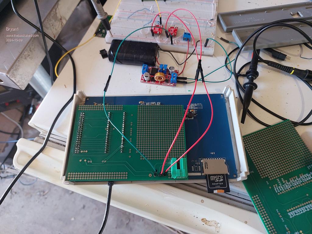
G'Day Guy's, Well those SSD1963 boards were there when I got home from holidays so made one up and first mistake as the 20x2 LCD connector is under the board the pico and the soldermask should have all gone on the C2 side  Now what I found was when the pico was connected to the board the led on the pico stopped and lost the console. Found by cutting the track between gnd and 3v3enable fixed that problem. Soldered on the power and ground pins this morning and no life from the LCD at all so there is some mistake there that I'm not seeing  Got correct power going to each rail and nothing looks to be shorted. Regards Bryan |
||||
Bryan1 Guru Joined: 22/02/2006 Location: AustraliaPosts: 1343 |
Well I reckon I have confirmed the 7" lcd is gone as I did setup a pico on the sea of holes where I got to the SDcard working but nothing on the screen, now what was interesting when I did try a GUI Calibrate got a message saying the SDCard was disabled. I have checked all the connections and they are right but no life from the LCD so I do think when I connected that first board I made killed it. Which does now bring on that second board I made where a Zero sits on the back of a OV7670 camera. Both the camera and Zero will need sockets fitted first to raise the Zero and second to give more room for mounting the camera. So finally I got onto some pico W's as the place I'm going to put these camera's is to capture local wildlife like that pic I just put in my thread in the section no-one reads  Ordering on Ali is a pita as what I bought first thinking it was a picoW was just more 2040 pico's so back on with a different seller and got 5 of them coming as I do have 5 camera's. Regards Bryan |
||||