|

|
Forum Index : Electronics : Micro controller driven Warpverter
| Author | Message | ||||
renewableMark Guru Joined: 09/12/2017 Location: AustraliaPosts: 1678 |
The wire is the recovered 1.6mm 2mm2 wire from the aerosharps. I tend to use the outer layers from torroids as they have the less severe kinks. I have a fair bit on spools lying around. Cheers Caveman Mark Off grid eastern Melb |
||||
| Warpspeed Guru Joined: 09/08/2007 Location: AustraliaPosts: 4406 |
Its all good Mark. Try and space the turns fairly evenly right around the whole toroid on each layer with just enough gap between the ends to ensure good insulation. Cheers, Tony. |
||||
| poida Guru Joined: 02/02/2017 Location: AustraliaPosts: 1419 |
if it was up to me, I'd use the 74ACT541 octal buffer/latch. 50mA drive, 8 bits in one dip package 20 pins and no invert of logic. Or some other plain old 8 bit buffer chip. wronger than a phone book full of wrong phone numbers |
||||
| poida Guru Joined: 02/02/2017 Location: AustraliaPosts: 1419 |
Thanks, Mark, I would like 4 of about the same size. I don't want to make a large power inverter, just something that follows the design principles as we develop things. Should I come over some time to pick them up? wronger than a phone book full of wrong phone numbers |
||||
| Warpspeed Guru Joined: 09/08/2007 Location: AustraliaPosts: 4406 |
That is a much better suggestion ! Cheers, Tony. |
||||
renewableMark Guru Joined: 09/12/2017 Location: AustraliaPosts: 1678 |
Thanks for the calcs Tony, full steam ahead. 104 sec x4 and 61 primaries. No worries.... sore fingers on the way. Poida, swing by when you can, reckon using a 2kw at least for no1 would be a good idea even if you want to make a little one, rest use the 1500's which I have plenty of. Give me a buzz re time/day. Cheers Cheers Caveman Mark Off grid eastern Melb |
||||
renewableMark Guru Joined: 09/12/2017 Location: AustraliaPosts: 1678 |
Hey do you need to tune each toroid for 75hz? Does each one need caps across the secondaries? Cheers Caveman Mark Off grid eastern Melb |
||||
| Warpspeed Guru Joined: 09/08/2007 Location: AustraliaPosts: 4406 |
No Mark, no tuning and no choke required. Its a whole different ball game. Cheers, Tony. |
||||
renewableMark Guru Joined: 09/12/2017 Location: AustraliaPosts: 1678 |
No choke even!!!! Bloody hell, this just gets better and better. Cheers Caveman Mark Off grid eastern Melb |
||||
| Warpspeed Guru Joined: 09/08/2007 Location: AustraliaPosts: 4406 |
Mark, just looking at some possible cable for your number two primary winding. Tycab Australia make 13.5mm squared very fine stranded single insulated cable MBS119203, available on a 30 metre drum (in red or black). http://www.tycab.com.au/marine/single-core-battery/ Sixty one turns of that should fit through a 70mm diameter hole with a bit to spare. After winding on four layers of 1.6 wire around an 87mm hole, you should easily have 70mm hole diameter remaining. Cheers, Tony. |
||||
| Mulver Senior Member Joined: 27/02/2017 Location: AustraliaPosts: 160 |
Pretty amazing! I’ll be in for any pcb’s that get produced! Wish I had the skills to contribute! |
||||
| poida Guru Joined: 02/02/2017 Location: AustraliaPosts: 1419 |
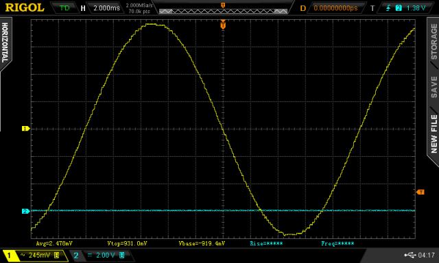
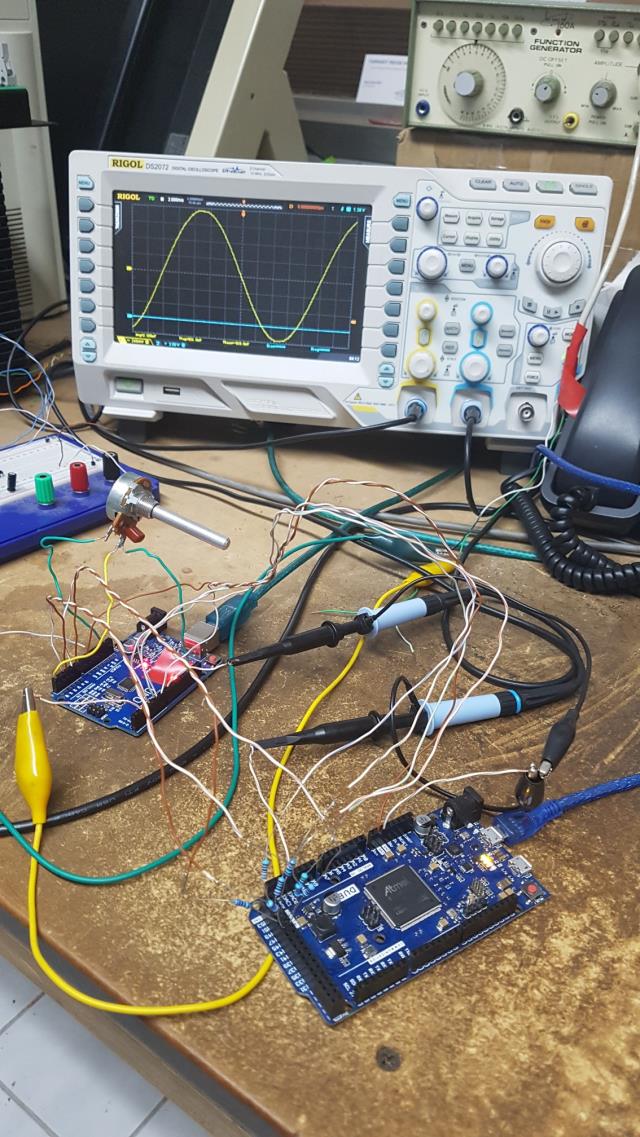
Mack: Like you I used the Arduino Due to simulate the 4 transformer inverter. here is the code, and I just put any inverter output into any of PORTC inputs in any order. (eyesight is no longer useful when tracing thin wires) I used 5K or whatever resistors to limit current when overdriving the Due inputs to 5V. void setup() { noInterrupts(); analogWrite(DAC0,0); pinMode(44,INPUT); pinMode(45,INPUT); pinMode(46,INPUT); pinMode(47,INPUT); pinMode(48,INPUT); pinMode(49,INPUT); pinMode(50,INPUT); pinMode(51,INPUT); // PORTC dacc_set_channel_selection(DACC_INTERFACE, 0); } void loop() { uint32_t p; uint8_t b; int v; while(1) { p = REG_PIOC_PDSR; b = p >> 12; v = 0; if (b & 0x02) v += 27; if (b & 0x01) v -= 27; if (b & 0x08) v += 9; if (b & 0x04) v -= 9; if (b & 0x80) v += 3; if (b & 0x40) v -= 3; if (b & 0x20) v += 1; if (b & 0x10) v -= 1; v += 40; dacc_write_conversion_data(DACC_INTERFACE, v * 45); } } It gives the expected stepped sine wave shape.  the hacker's hacked up hack:  video of how the various bits switch on and off, adding or subtracting their 1,3,9 or 27 units to the amplitude as I twiddle the pot. And it was synchronised to the blue trace squarewave at about 48.78Hz wronger than a phone book full of wrong phone numbers |
||||
mackoffgrid Guru Joined: 13/03/2017 Location: AustraliaPosts: 460 |
I've done a DUE based step Inverter Simulator: You feed in the 8 non-inverted outputs of the Step Inverter (of any kind, whether it be an eprom based or micro based) and it scans it at a 10uSec sample rate. The input is translated into a voltage > 12bit value and is written to the DUE's DAC in real time. The image below is of my Eprom based board, but it could just as easily be the new micro based prototype. The DAC of the DUE seems a bit noisy, and my DSO was syncing to small ~100khz transitions rather than the big picture so I made D27 go high whenever the input, 8 lines were all zero. The DSO liked to sync on that.  As Tony has told me, the good thing is you can vary the battery voltage, and watch how it changes. Etc. There will be an option for grabbing a frame of data and transmit the data over the SerialUSB in CSV format. Cheers Andrew |
||||
mackoffgrid Guru Joined: 13/03/2017 Location: AustraliaPosts: 460 |
Poida: talk about timing  Your Scope displays a much nicer image than mine. I came at it from a different direction than you did. I started out intending to display a plot on an LCD, so implementing grabbing frames of data to export to serial and display. I decided I couldn't be bothered by the LCD and implemented the DAC. I like the simplicity of yours and it shows more simply, how the inverter works. Cheers Andrew |
||||
| poida Guru Joined: 02/02/2017 Location: AustraliaPosts: 1419 |
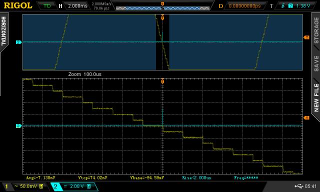
I usually find the DSO of mine shows cleanest traces when I choose "High Res" from the Acquire menu. This averages many samples together and then displays that one average value on the screen at each pixel's time value. Eg maybe 640 pixels wide, time base is 2ms/div, 10 divs screen width So a pixel might be about (2ms x 10)/640 = 31us each. The DSO might be sampling at 2M samples/sec, so each pixel is the average of 62 samples. This crushes noise. Your DSO, OWON PDS5022S, does not have this high res mode. You do have 2 things to help. First, I would enable the HF reject on the trigger, under "Coupling" in "edge trigger menu". And I would use under Acquire menu, the Average function, maybe 4 or 16 averages. This should clean things up. DSOs have shown to the great unwashed masses how much noise is present within a scope's front end. (just short ch1 with small wire and see the trace still appear "noisy".) CRT scopes don't show it to human eyes very well due to each trace is showing the new noise, never overlapping the previous trace's noise. CRT traces look cleaner. Only 'cos we can't see the noise. It's there... Maybe just for you and me, here is a closeup of the zero crossing, clearly showing the steps as it approximates the sine function at various times.  wronger than a phone book full of wrong phone numbers |
||||
| Warpspeed Guru Joined: 09/08/2007 Location: AustraliaPosts: 4406 |
Its really interesting to scroll through several lookup tables. The difference between two adjacent tables might be only about half a percent in overall amplitude. But the time lumpiness visible in the individual step timing, changes radically from table to table when viewed up really close in fine detail. If you can make a total harmonic distortion measurement of your waveform, you might be surprised how low it is. Cheers, Tony. |
||||
| poida Guru Joined: 02/02/2017 Location: AustraliaPosts: 1419 |
for sure. I see the problem of approximating a continuous function with discrete values. If we need 3.665789 but can only get 3.00000 or 4.00000 then the art becomes choosing the "best" one at the time. wronger than a phone book full of wrong phone numbers |
||||
| Warpspeed Guru Joined: 09/08/2007 Location: AustraliaPosts: 4406 |
Yes indeed. My humble program did not use any rounding at all, and I generated only the first ninety degree quadrant. Where the segments joined up at the peaks and zero crossings was far from perfect. But I was amazed at how good the final results actually turned out. Cheers, Tony. |
||||
| Tinker Guru Joined: 07/11/2007 Location: AustraliaPosts: 1904 |
No, Mark is *very* unlikely to have a 70mm hole in that toroid available for the primary winding. I use the exact same core, double stacked. The original hole is more like 85mm (its not exactly round so measure at a different place. Then, by the time sufficient mylar tape is wound on to provide good insulation (I wound it half overlap on outer rim, twice around the toroid, this hole has shrunk a bit more. Now, in my case, using 1.8mm wire, I could fit 127, 125, 119 turns on the respective layers. Second hand enameled wire is not straight enough, nor has the elbow winding machine enough power to pull it straight  , so the theoretical number of turns for the hole size does not apply to toroid winding. , so the theoretical number of turns for the hole size does not apply to toroid winding.Also, a wise winder winds a single layer (half overlap) of mylar tape around every completed winding layer. This is because recycled enameled wire might have micro cracks in the enamel, reducing its insulating properties. If the turns are just side by side the voltage between each turn is quite small, ~2V. but would be much larger if overlapping turns were applied with no added extra insulation between. For that same reason I always epoxy in a bit of string between the first & last turn of each layer to make sure these wires do not touch one another. Since I required 169 turns per 'hand' of the secondary, the number of turns noted above, on each layer, was not enough. So a fourth layer will accommodate the extra turns for 'hand' #1 & 2 and a fifth layer for the rest. I would be surprised if Mark does not face the same dilemma. On top of the completed winding go at least 2 overlapping layers of mylar tape, then the electrostatic shield which also eats up hole diameter. And another double layer of mylar tape on top of that, reducing the hole further... If I was in Mark's shoes I would hold back with any primary cable purchase until all of the secondary and that static shield is in place. Then, and only then, measure what size hole is left and calculate what kind of wire will fit the required primary turns through it. I have just completed 3 layers of secondary on my core and write from experience here. I would be very happy if the final hole size stays north of 50mm diameter. My comments relate to the 'big' transformer, the one with a 225V secondary. I think this transformer should be wound first. I did some back of the envelope calculations which tell me that there will be a snag here for those who plan to build a 'small' warp inverter with small toroid cores. If one wants to stick to 1 Tesla, as warpspeed suggests - and there are very good reasons for that - then one requires a decent core cross section, and decent 'hole' for the first transformer or the required number of turns wont fit through the hole Klaus |
||||
mackoffgrid Guru Joined: 13/03/2017 Location: AustraliaPosts: 460 |
Poida: Yes, the Owon is no RIGOL  and you drive that Rigol like it's a car and you drive that Rigol like it's a car  My old Owon is over 10 years old now and has proven to be a very good purchase, but it wasn't meant to be my Scope but that's another story. I used to have a really nice 4ch DSO, back some decades ago, and lately I'm finding myself really missing a good 4ch DSO. My old Owon is over 10 years old now and has proven to be a very good purchase, but it wasn't meant to be my Scope but that's another story. I used to have a really nice 4ch DSO, back some decades ago, and lately I'm finding myself really missing a good 4ch DSO.I've seen the sinewave out of the transformers for real, but even now looking at the output of the simulators, it amazes me how four transformers with three states can make such a good looking sinewave. Very cool Tony!  I'll get back to tidy up my Simulator code tomorrow but basically like yours but with a button press to capture a frame and transmit the data to the PC. btw, I used C1 to C8 , in order, with switch inputs at C12 and C14. Cheers Andrew |
||||