
|

|
Forum Index : Electronics : Power Jack expert help needed
| Author | Message | ||||
| BenandAmber Guru Joined: 16/02/2019 Location: United StatesPosts: 961 |
Yahoo2 he sells his book with boards I am hoping for nano if that dont wotk out I will try to get him to sell me board without book again Thanks for the advice I appreciate it be warned i am good parrot but Dumber than a box of rocks |
||||
| Tinker Guru Joined: 07/11/2007 Location: AustraliaPosts: 1904 |
It sets too brittle for my liking, that resin needs glass reinforcement to become strong. You can make a very good glue with epoxy resin and a thickening agent. The longer curing time of epoxy is an advantage as it allows the stuff to seep into crevices and lock the wires together firmly. Polyester resin only sticks well to itself. It may appear to stick to whatever it is applied to but over time can fall off just as easily. Beside, that stuff smells horrible  Klaus |
||||
| BenandAmber Guru Joined: 16/02/2019 Location: United StatesPosts: 961 |
I just noticed that rating system by my name I couldn't be the only one laughing be warned i am good parrot but Dumber than a box of rocks |
||||
| LadyN Guru Joined: 26/01/2019 Location: United StatesPosts: 408 |
No, you're the only one. The amount of experience you have built is staggering. Now go ahead and make some HOWTO videos and posts!  |
||||
| tinyt Guru Joined: 12/11/2017 Location: United StatesPosts: 438 |
I noticed that by my name too. I think it is based on number of posts only as I am no guru. |
||||
| BenandAmber Guru Joined: 16/02/2019 Location: United StatesPosts: 961 |
I barely know how to tie my shoes they have me as a guru LOL LOL I am good at monkey see monkey do and usually pretty good at following directions I have done nothing new I have learned a whole lot on here there are some really smart people on here that have devoted their whole life to this stuff And I am happy riding their coattails be warned i am good parrot but Dumber than a box of rocks |
||||
| BenandAmber Guru Joined: 16/02/2019 Location: United StatesPosts: 961 |
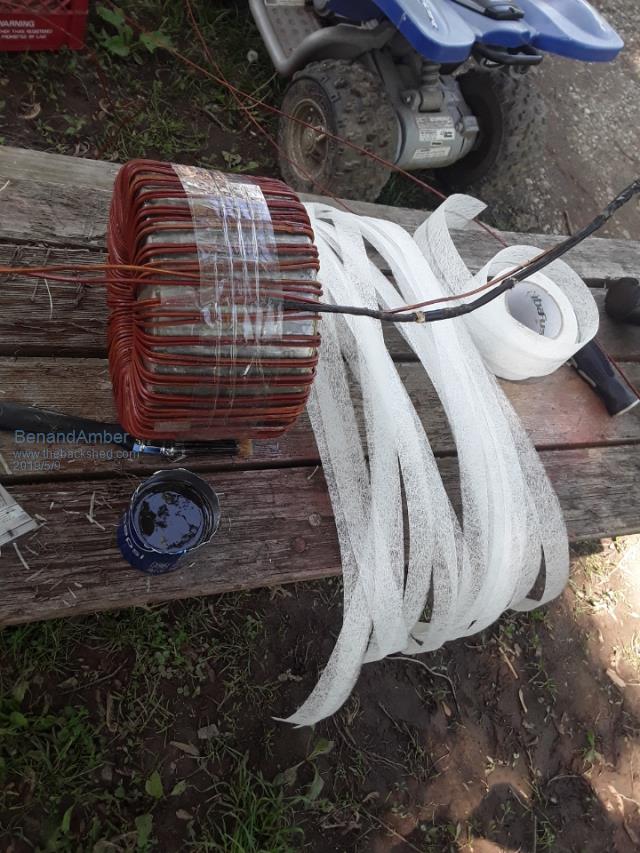 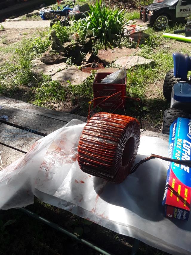 Getting ready to epoxy the first layer of wire see the fiberglass tape I'll be winding around it I cut it in short pieces to make it easier 2 wind Thanks tinker for the idea and advice be warned i am good parrot but Dumber than a box of rocks |
||||
| BenandAmber Guru Joined: 16/02/2019 Location: United StatesPosts: 961 |
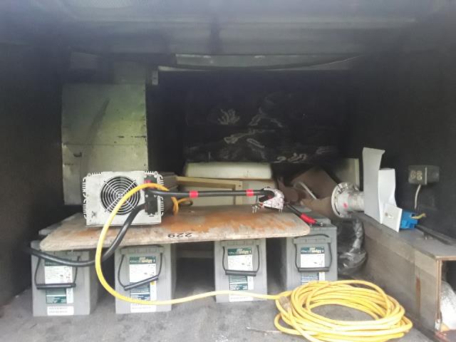 Little Energizer Bunny just keeps going and going I did put a 30 amp dc breaker on it like poida the great told me to It flips often be warned i am good parrot but Dumber than a box of rocks |
||||
| BenandAmber Guru Joined: 16/02/2019 Location: United StatesPosts: 961 |
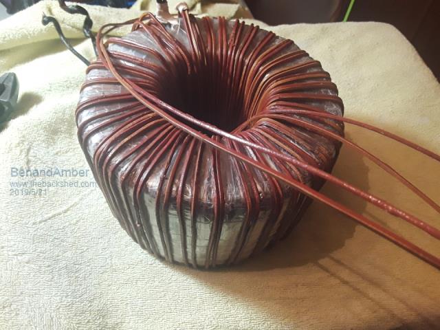 Got a chance to wind another layer Running out of space we decided to go with 1 in hand 3mm Square wire not round Square Just not enough room to fit into the power Jack case if I went to in hand sucks but it is what it is Hopefully I can get 4000 watt continuous and peaks of six or seven just for a few minutes It probably doesn't really matter anyway because I doubt if I run over 2000 Watts continuous I just don't have the batteries for it 8 145 amp hour batteries at 48 volt so 290 at 48 Can only fit 10 solar panels on top of RV we will be having six of them on a rack type awning we can set up if we're going to be in one spot for more than a day Solar panels are 330 watts each around 3000 on the roof and about 5,000 all together Mppt charge controllers My first Solar setup so I hope it works out okay be warned i am good parrot but Dumber than a box of rocks |
||||
| BenandAmber Guru Joined: 16/02/2019 Location: United StatesPosts: 961 |
I had a chance to epoxy the last layer of the high side secondary After the epoxy dried I wound it with two layers Transformer tape now I am ready for the low side Not real sure at how many volts I should wind it for the original Power Jack was 32 volts I was hoping and praying I could use a nano on this but I'm not exactly sure how many volts I should wind a secondary for for a nano be warned i am good parrot but Dumber than a box of rocks |
||||
renewableMark Guru Joined: 09/12/2017 Location: AustraliaPosts: 1678 |
How have you calculated the windings? What exactly have you done so far? Cheers Caveman Mark Off grid eastern Melb |
||||
| BenandAmber Guru Joined: 16/02/2019 Location: United StatesPosts: 961 |
My calculations for the core was a little over 1 volt per turn So for a hundred and twenty volt it would have been about 118 to 119 turns I ended up putting 146 turns (i think) on it that's what filled the core up nicely I had heard warpspeed saying to add extra turns and figured that this would not hurt it I wound three turns of scrap wire around it and fired it up with a light bulb a switch and Mains voltage And the reading was 2.46 volts with full mains voltage And the idle current was 0.31 That is a little bit higher than what I was expecting But this is a home wound core So for 32 volts that would be about thirty-nine turns for the low side primary My problem is I don't know what voltage I need for the low side primary it was originally 32 volts with the power jack control board I am hoping I will be able to use a nano for the control board Thanks for your interest and your help be warned i am good parrot but Dumber than a box of rocks |
||||
| tinyt Guru Joined: 12/11/2017 Location: United StatesPosts: 438 |
If I remember, there were a lot of discussions about the turns ratio between the pwm'ed primary supplied by battery DC and the desired sine wave secondary. And the magic number was 1:9 for a 48VDC battery and 240 VAC output. This turns out to be 26V pwm'ed primary. So to scale your 146 turns at 120VAC to 240VAC so that we can apply the magic number: 146 x 2 = 292. 292 / 9 = 32 turns for 26V pwm'ed primary supplied by 48VDC. This is using EG8010, I assume it will be the same when using the nano control board. |
||||
| nickskethisniks Guru Joined: 17/10/2017 Location: BelgiumPosts: 458 |
I used 1/7,5 with the OZinverter. |
||||
| BenandAmber Guru Joined: 16/02/2019 Location: United StatesPosts: 961 |
That means a whole lot coming from you tinyt And I appreciate your info Nick I'm sorry I don't understand what you're saying be warned i am good parrot but Dumber than a box of rocks |
||||
| tinyt Guru Joined: 12/11/2017 Location: United StatesPosts: 438 |
I think here is where I got the number from (1:9). But in another forum here He says something else (28:240 or 1:8.57). So I did some calculations using desired sine wave output of 240VAC and 48vdc battery. Peak AC is 240 X 1.414 = 339.36 volts Using the ratio of 1:9 the calculated PWM "peak DC" voltage is 339.36 / 9 = 37.7vdc minimum battery voltage to get 240Vrms. (240 / 9 = 26.67 vac) Using the ratio of 1:7.5 the calculated PWM "peak DC" voltage is 339.36 / 7.5 = 45.25vdc minimum battery voltage to get 240Vrms. (240 /7.5 = 32 vac) Since it is recommended not to discharge the battery lower than 50% of full charge (48.4vdc and ratio of 339.36 /48.4 = 7.01), the 1:7.5 ratio from nick will still work. I am no expert but I think that within limits, the lower ratio (more primary turns) will give you lower transformer losses. |
||||
| nickskethisniks Guru Joined: 17/10/2017 Location: BelgiumPosts: 458 |
Yes, thank you tinyt for the explanation. In my OZinverter with clockman boards I used 150 turns for the 240V Winding, 20 turns for the 48V side. I used a transformer core with 72cm^2 cross section. I used 10mm^2 and 70mm^2 wire, so losses are verry low. Idle was around 15W I think. I normally go not below 50V battery voltage. I never noticed voltage drop above 46V battery, but I won't mind if it would drop below 225V. (My eg8010 chip has no low voltage protection.) Everything works just fine, but I have to say that if you work with high powertools you would like to have 240V instead of 220-230V. |
||||
| BenandAmber Guru Joined: 16/02/2019 Location: United StatesPosts: 961 |
I'm trying to understand it all tinyt be warned i am good parrot but Dumber than a box of rocks |
||||
| tinyt Guru Joined: 12/11/2017 Location: United StatesPosts: 438 |
I made a sketch of what I think the waveforms are for a 240VAC rms sinewave with the PWM superimposed on it. For a sine waveform, the relationship between the root-mean-square(rms) and its peak is: peak = rms x 1.414 or rms = peak x 0.707 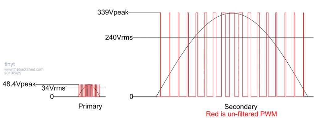 The sketch is for the ideal case and the 48V battery is at 50% state of charge. The highest voltage on the primary side will be the battery voltage and is the peak voltage for a sine wave. So the equivalent rms will be 48.4 x 0.707 = 34.2 VAC (same as 48.4 / 1.414). If you want your secondary to be 240VAC at this condition, the ratio will be 240 / 34.2 = 7.017. or 1:7. But this does not consider losses in the choke, wiring, mosfets, etc. When the battery is between 50% thru 100% state of charge, and the PWM electronics can monitor and regulate for output voltage changes, the 240VAC can be maintained and hopefully also the waveform. At the ratio of 1:7, when the battery voltage drops lower than 48.4, the pwm electronics might still regulate but the peak of the waveform will now become lower together with the rms value. So, within limits, it is better to use a higher ratio. I am no expert. But this is the way I understand it. |
||||
| BenandAmber Guru Joined: 16/02/2019 Location: United StatesPosts: 961 |
Tinyt you've done so many experiments you'd have to be an expert I'm just doing 110 / 120 volts on all my stuff in the RV You know how the 8010 requires 28 volts and the Power Jack requires 32 volts I'm wondering what a power jack would require with a nano board If I can figure that out I'll plug the transformer into the mains voltage after I wind the estimated turns and then fix it from there At least this is what I've done in the past could possibly be the wrong way be warned i am good parrot but Dumber than a box of rocks |
||||