
|

|
Forum Index : Electronics : Warpspeed’s low frequency stepped sine
| Author | Message | ||||
| Tinker Guru Joined: 07/11/2007 Location: AustraliaPosts: 1904 |
Not quite Andrew  . .Mine have the heat sink fin tops facing each other and no angle brackets. The caps will be on the other side of the PCB - I do these things differently from anybody else  . .Klaus |
||||
mackoffgrid Guru Joined: 13/03/2017 Location: AustraliaPosts: 460 |
I get accused of doing things differently from everybody else too  Its more Fun that way Its more Fun that way  |
||||
| Warpspeed Guru Joined: 09/08/2007 Location: AustraliaPosts: 4406 |
O/k understood Klaus. The four square wave transformers need to have secondary windings that go up in increasing voltages, with voltage ratios with respect to each other of 1, 3, 9, and 27. If all four inverters switch on together in the same direction (either +ve or -ve) and if all the secondaries are placed in series, then a the square wave voltages add together. Assuming we wish to make a 235.67v rms sine wave, we need to be able to reach a peak voltage of 333.3 volts. So all the secondary voltages must add up to 333.3v and have the correct relative voltage ratios. We can make the highest voltage secondary 225v. The second secondary will be exactly one third of that 75v The third transformer secondary would be one ninth or 25v And the fourth transformer secondary 8.33 v All these secondary voltages have been chosen to give as close to whole integer voltages to make transformer design and the turns ratios easier to work with. The final output voltage may not necessarily have to be exactly 235.67 volts, because our inbuilt voltage regulation provides a potentiometer adjustment that we can adjust to get 220v, 230v, or 240v or anything in between. But we need to have some initial transformer design voltages to work with when winding our transformers. So if everyone designs their transformers to have secondaries of the suggested 225v, 75v, 25v and 8.33v, the inverter output can then be tweaked up or down slightly to get the exact final rms output voltage desired. Its just a convenience thing. Much easier to work out an exact turns ratio if the secondary voltage is exactly 75.0v, rather than 73.57 for example. The transformers will all have primary voltages to suit the lowest dc voltage the inverter will see. Turns ratio will then be just the relative square wave voltages between primary and secondary, and they can be whole volts, except for the smallest secondary which theoretically should be 8.33v. But close will be good enough for that. Its rather important that the secondary voltages all be fairly exact, if our final very small steps are going to be even. The basic transformer design will suit any country, as the final output voltage can be potentiometer adjusted. Either 50Hz or 60Hz is just a crystal oscillator frequency change. Cheers, Tony. |
||||
| Warpspeed Guru Joined: 09/08/2007 Location: AustraliaPosts: 4406 |
Klaus, The top four waveforms are the secondary voltages of the four inverter transformers shown in correct amplitude relationships. The lower three waveforms are the voltage produced when these transformer secondaries are connected in series. 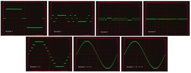 Cheers, Tony. |
||||
| Warpspeed Guru Joined: 09/08/2007 Location: AustraliaPosts: 4406 |
This is a larger picture of the final waveform. 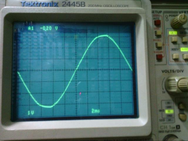 Cheers, Tony. |
||||
| LadyN Guru Joined: 26/01/2019 Location: United StatesPosts: 408 |
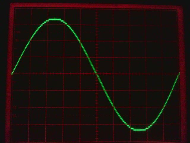 |
||||
| Warpspeed Guru Joined: 09/08/2007 Location: AustraliaPosts: 4406 |
Thats the picture I was looking for but could not find. Cheers, Tony. |
||||
| Tinker Guru Joined: 07/11/2007 Location: AustraliaPosts: 1904 |
Thanks Tony, beautifully explained and very much appreciated. I started making notes on this as my leaky brain seems to forget at which post what important info was presented  . .Anyway, since I passed on the 3KW toroid I had I'm planning now to go even bigger  than your build by using double stack 2.5KW Aerosharp cores for transformer #1. than your build by using double stack 2.5KW Aerosharp cores for transformer #1.These have a combined cross section of 6175mm sq of core laminate. For transformer #2 I have the core from a 1KW Fronius which has a 2205 mm sq cross section core, close enough to be 1/3 to transformer #1. I suppose with these size cores I can underrate the flux density and give them an easy run at low idle current - any suggestions here? Transformer #3 & 4 is not yet decided upon, I have double C core types in my parts box which is easy enough to re wind and may suit, will worry about that when I need them. Klaus |
||||
| Warpspeed Guru Joined: 09/08/2007 Location: AustraliaPosts: 4406 |
Klaus, if you begin with the largest toroid, and design that for 50Hz sine wave operation with a turns ratio of the minimum expected dc input voltage up to 225v, and the required final secondary current required from the inverter. If you then use the very low design flux density of 1.0 Teslas, it should have both a very low idling current, and absolutely minimal inrush current surge when initially powered up. If we do that, we can completely avoid needing a soft start. Its one less thing that can possibly go wrong ! Its all made a lot easier by designing for conventional sine wave operation at 50Hz, because all the books and design calculators on the internet can then be used directly. And the results will be as expected. Nothing really different to designing for an oZ inverter, except the primary will probably end up needing about 50% more turns, and the primary wire can be made proportionally thinner. Its going to look very different to an oZ transformer, but the application calls for these changes. Current density in the wire for both primary and secondary should be kept about the same, possibly about 4 amps per mm squared might roughly determine your maximum continuous final power rating. The second toroid will be exactly the same, except the secondary will be 75v. Again use 1 Tesla, and design for 50Hz sine wave operation at the required voltages. This will actually operate at higher than 50Hz, and the actual working flux density below the design 1 Tesla. But the exceptionally low resulting flux density will ensure eddy current losses in the core will be as low as they might have been if the transformer were actually operating at 50Hz. This is something I discovered by trial and error. Excellent results can be obtained if all four transformers were designed to run at their design voltages with 50Hz sine waves. It makes things much easier, and it will work very well. Cheers, Tony. |
||||
| Warpspeed Guru Joined: 09/08/2007 Location: AustraliaPosts: 4406 |
O/k here we have the overall wiring diagram for the entire inverter. 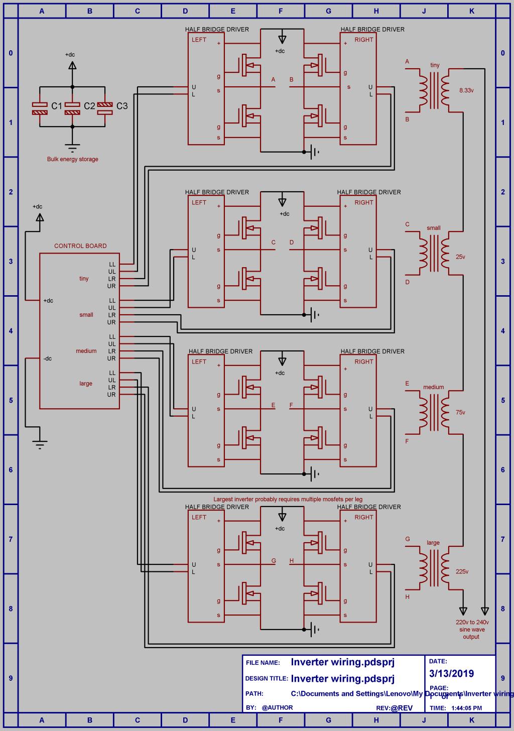 The control board just generates some drive waveforms appropriate to the measured dc input voltage. There will be eight identical half bridge driver boards, that just have a pair of 15v isolated dc supplies, and a pair of opto isolated gate driver chips on each. Schematic of that to come very shortly. The three smaller inverters just use four mosfets. The largest inverter will probably require multiple mosfets per leg, depending on the power level. Or alternatively single large devices such as mosfet or IGBT power blocks. And of course four transformers. And some large electrolytics, and probably an EMC filter on the output just to finish things off. A fair few parts, but its really quite basic. Just noticed C3 is upside down, and a few other minor things need tidying up, but the schematic is correct enough to convey the basic concept. Cheers, Tony. |
||||
| LadyN Guru Joined: 26/01/2019 Location: United StatesPosts: 408 |
The "bulk energy storage" are the low ESR RIFA caps? I am assuming the polarity of C3 reversed is just am oversight |
||||
| Warpspeed Guru Joined: 09/08/2007 Location: AustraliaPosts: 4406 |
Yes C3 is standing on its head. Should have spent a few more minutes looking at it before I posted. Did not give values or part numbers for mosfets or capacitors, or primary voltages of transformers. That all depends on the dc operating voltage, and the desired power level. For sustained very high power use, low ESR RIFA caps are recommended. For lower power, or for an initial experimental bench prototype, ordinary aluminum capacitors should be up to the job. If an electrolytic does not start getting really hot in use, its a happy content electrolytic. Cheers, Tony. |
||||
| Solar Mike Guru Joined: 08/02/2015 Location: New ZealandPosts: 1138 |
Read in a manufactures spec sheet, every 5 degrees Celsius temperature rise lowers their life by 50%, so if you want 15+ years then top quality electro's must be used. Another way to lower the ESR and reduce internal heating is to use lots of smaller caps in parallel with the advantage of more surface area for cooling and perhaps less expensive. Mike |
||||
| Tinker Guru Joined: 07/11/2007 Location: AustraliaPosts: 1904 |
I'm still a bit stumped with the above explanation  . .There is mention of a "transformer ratio" and then of a "turns ratio". So I understand the turns ratio means the secondary has 5.62 time as many turns as the primary in the above example? So what significance has the "transformer ratio" when I design these transformers? Is it the ratio between primary and secondary currents? Thanks. Klaus |
||||
| Warpspeed Guru Joined: 09/08/2007 Location: AustraliaPosts: 4406 |
Klaus, We have two totally different situations. Lets assume we are working from a 40 volt dc supply. A square wave inverter will have a 40 volt peak square wave developed across the primary, and we want to have a 225v peak square wave in the secondary. The turns ratio of the transformer to do that will need to be 225/40 = 5.625:1 A PWM inverter running from the same 40v can only produce a sine wave with a 40 volt peak at maximum full duty cycle. That would be a 28.284 volt rms waveform across the primary. If we wanted to step that up to 230 volts rms, the turns ratio of the transformer to do that will need to be 230/28.284 = 8.13:1 Cheers, Tony. |
||||
| Warpspeed Guru Joined: 09/08/2007 Location: AustraliaPosts: 4406 |
This is all very true and rather important. If only running at comparatively low power, or for short term prototype testing, use whatever you have, and have fun. For serious long time reliability, especially at sustained high power, keep your electrolytic capacitors as cool as possible. If they must work with very high ripple current they are going to have a fair bit of self heating. As with any component read the data sheet and stay within the manufacturers ratings, preferably well within the maximum ratings. Cheers, Tony. |
||||
| Warpspeed Guru Joined: 09/08/2007 Location: AustraliaPosts: 4406 |
Here is the schematic for one (of the eight) half bridge driver boards: 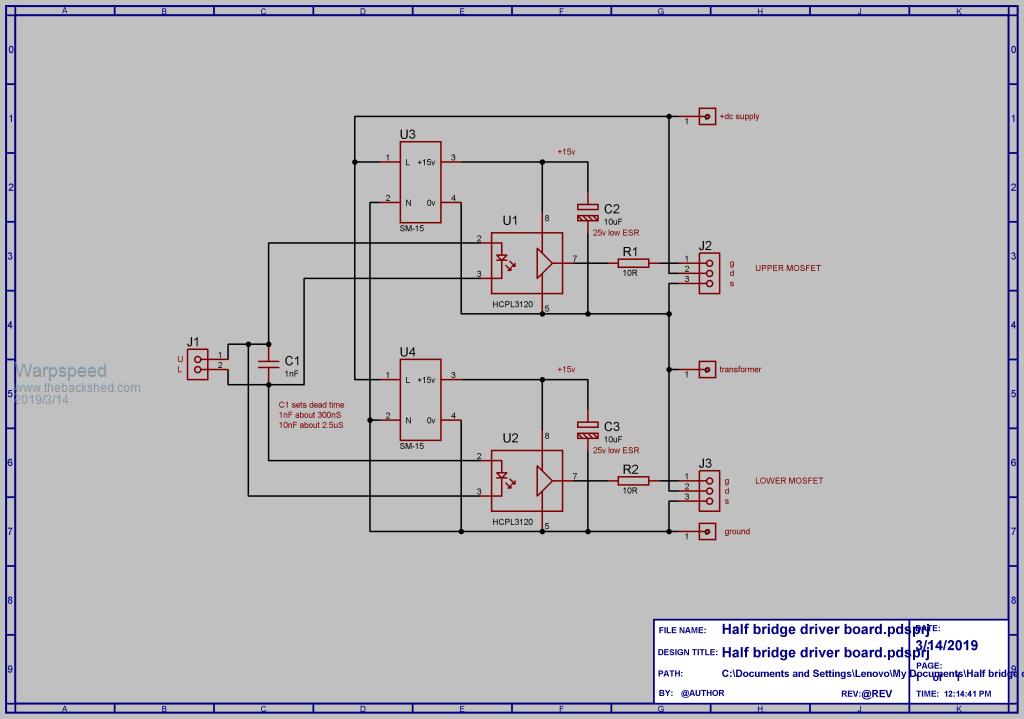 This deceptively simple circuit has a few very valuable features that go a very long way towards making the whole inverter pretty bullet proof. The U/L twisted pair from the control board dives a pair of opto isolated mosfet gate drivers, and the LEDs of these are connected in inverse parallel. This makes it impossible for both upper and lower gate drivers to be on simultaneously. This provides very simple and effective cross conduction protection under any conditions. To turn one opto isolator off, and the other on, the U/L drive voltage must slew through zero, where both opto isolators will both be off. The symmetrical dead time produced will be about 50nS, but we can increase that by any amount by fitting C1. These opto isolators provide extremely high noise immunity, and also prevent any blowups from propagating back into the control board. The HCPL3120 also has an internal undervoltage lockout to prevent any misbehavior during power up, and power down, or brownout. As we are only switching at a very low cycle rate, the HCPL3120 can easily drive multiple very large mosfets or IGBTs with ease through suitable gate resistors. U3 and U4 are small five watt isolated switching power supplies of postage stamp size. If very lightly loaded, as they are here, they will start up and run from about 30v, and operate safely up to around 400v dc input. In my inverter I have seventeen of these small supplies. One on the control board, and sixteen on the eight half bridge driver boards. The combined running power of all the electronics in the entire inverter (with the transformers disconnected) will be 5 watts. Cheers, Tony. |
||||
| Tinker Guru Joined: 07/11/2007 Location: AustraliaPosts: 1904 |
We have two totally different situations. Lets assume we are working from a 40 volt dc supply. A square wave inverter will have a 40 volt peak square wave developed across the primary, and we want to have a 225v peak square wave in the secondary. The turns ratio of the transformer to do that will need to be 225/40 = 5.625:1 Thanks Tony. I should have realized you quoted the RMS bit just for comparison...  . .I looked up a online calculator to get me turns/volt for a certain core cross section and one tesla flux. Does this work for square wave input too? I would then use the turns ratio that corresponds to the quoted above adjusted for my battery bank. Klaus |
||||
| Tinker Guru Joined: 07/11/2007 Location: AustraliaPosts: 1904 |
Thanks for posting all these schematics, they help a lot to see what's required. A big stumbling block would be the control PCB, I can easily lay out the others to suit my mechanical arrangement. Another downer is the price of those big caps  , with the second hand ones on ebay one never knows how much life they got left in them. , with the second hand ones on ebay one never knows how much life they got left in them.Now, this got me wondering, would supercaps work? I know, one needs a string of 30 or so in series for a 48v nominal battery bank. But even if using small ones (30F for example) one still ends up with one Farad of capacitance, way more than warpspeed uses and cheaper too. With the stud mounted ones high power connections are easy but the pack is quite a bit bigger than electrolytic caps. 30 off 2,7V supercaps at around $5 ea are cheaper than a 47000/100v new cap sells at RS components. Regarding supercaps, I used a bank of 12 x 3000Farad in series way back when I started with 24v LA batteries running a bought inverter. That certainly got rid of the fridge or compressor startup problems. That 3000F supercap bank has been hanging unused on the wall for a few years now and today I checked it and found there was still 17V charge potential. I used simple LED's and resistors to keep each cap in balance, seems to work but balancing boards are to be had on ebay too. Klaus |
||||
| Solar Mike Guru Joined: 08/02/2015 Location: New ZealandPosts: 1138 |
Super caps: Somehow don't think their use in an high power inverter would be successful, the continuous high charge and discharge currents would mean a very expensive balancing scheme would be required for your 30 or so series devices. Better to get a big parallel bunch of 200v low esr electros; such as these 200v 2200uf RS #744-1192, $8-80 each 10 off. ripple current 7 amps, so 10 in parallel will give you 70 amp. Cheers Mike |
||||