
|

|
Forum Index : Electronics : Random Unexplained Inverter Failures
| Author | Message | ||||
| wiseguy Guru Joined: 21/06/2018 Location: AustraliaPosts: 1156 |
No I havent built an inverter yet but it is on my to do list. I have built thousands or rail power supplies with Dc to Dc synchronous rectification though to Rail standard EN50155 with up to 60A output. I doubt you could find a train in Australia without at least one of my power supplies on board. The majority run 24/7 and have since 1998 without recorded failure. I have also designed and built a switchmode charging system for Exide (formerly GNB) that controlled over 1MW of power - please dont assume what I am capable of or not. Poida has & uses one of my creations the Power-Mate lite. After I created it I set a challenge that if anyone could find a better unit with better performance and features in the world I would buy it for them - never cost me a cent. It measures down to 10milliwatts accurately and can cost a kids night lights consumption at 60c per year - the manufactures of the energy IC I used denied that it was actually possible. I dont need your kudos and I dont need all this aggravation - ok I withdraw my offer to redesign the adaptor board - live with it ! I will continue to provide information to the forum for those that are interested but I dont want further aggravation if anyone disagrees with what I write please just ignore it. If at first you dont succeed, I suggest you avoid sky diving.... Cheers Mike |
||||
| wiseguy Guru Joined: 21/06/2018 Location: AustraliaPosts: 1156 |
The IR2110 does not have dead-time it has a slight difference between Turn on and turn off propagation delays and thats it as far as I can interpret. I am confident the transistors make the difference. If you check at the input hi and lo pins of the IR2110 I am sure you will see the shoot through has gone before passing through the IR2110.. If at first you dont succeed, I suggest you avoid sky diving.... Cheers Mike |
||||
| Warpspeed Guru Joined: 09/08/2007 Location: AustraliaPosts: 4406 |
I never noticed this on my EGS002, probably because I never used the the temperature sensor or fan control system. My experimental PWM inverter was only 1.5Kw and it used a whole uncut Inspire heatsink mounted vertically without needing any fan. That glitch can only be a software bug, and nothing we can do about it directly. That inverse opto isolator gate driver circuit I suggested earlier in this thread would definitely get rid of it. Cheers, Tony. |
||||
| Warpspeed Guru Joined: 09/08/2007 Location: AustraliaPosts: 4406 |
This "Oz type inverter" I built was nothing like what you guys are building. I took the Wiseguy approach and designed it from scratch and its totally different in physical layout. Firstly its all on one circuit board with short and direct tracks, and a very careful grounding layout. It only uses four single mosfets in the bridge although I made provision for eight mosfets. And each mosfet pair has its own personal TC4452 high power gate driver. The screw terminal blocks were a very new idea at the time. It also runs at 100v dc so its only switching less than 20 amps. Its really just a baby... It also has a very large non saturating choke, and transformer is tuned to 75Hz. No fan or temperature sensing, just not needed. It does have a current transformer and fast SCR type of over current shutdown. I built it my own way, (using the Wiseguy approach) and thinking it all right through in detail before I started to lay the whole thing out. I managed to avoid many of the potential problems you guys are still facing, and from this latest "glitch" revelation I have also been very lucky to avoid that unexpected problem and possibly others as well. This is the original prototype, its a very similar circuit to what others here are using, but physically very different. 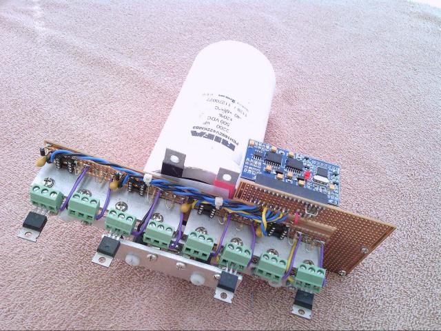 Final PCB with voltage feedback, +12 and +5 supplies, current limit, and reset button: 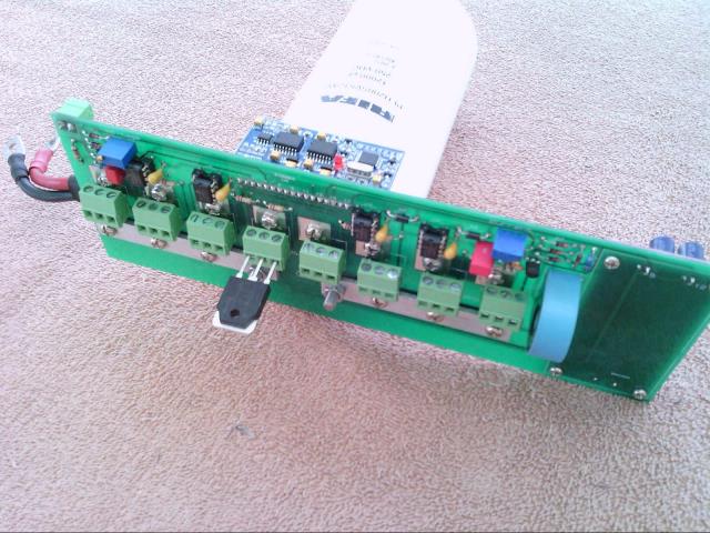 Mounted on its fan free heatsink: 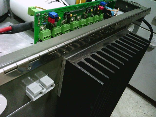 If I remove the four screws holding down the four mosfets, and loosen the big nut on the base of the electrolytic, the whole board can be lifted out complete in around one minute, and then run on the workbench. Cheers, Tony. |
||||
| poida Guru Joined: 02/02/2017 Location: AustraliaPosts: 1418 |
My view is 200ns of shoot-through is too long to permit to occur. HY4008 mosfets are tough in some respects but weak in others. They may survive (for example) 100 events of this short period of short circuit but then start failing some time after. Much depends on the impedance of the DC bulk capacitors and wire thickness that connects the FET bridge to the capacitors. Some of us here have built inverters with very low impedance, others not so low. My inverters have bulk capacitance about 1/10th or less than what I have seen here become the usual design. (Madness's boards for example). So a very low impedance means very high current during shoot-through. A little higher impedance means less stress on the mosfets during shoot-through and that is why I like my boards to have 1/10 the capacitance. Shoot-through occurs in other circumstances with our inverters. I am talking about the dV/dT induced voltage spike seen on the gate of the low side mosfet. What happens is the low side mosfet gate voltage rises(or falls..) as a consequence of the fast rate of change of the Drain-Source voltage when the high side mosfet switches ON or OFF really quickly. I have observed repeatedly this effect on my inverter boards. The voltage rise is just enough to start the low side mosfets conducting. The rise is not enough to make them fully switch on, in my case at least. But the gate does get a short pulse of about 4 or 5V and it comes from WITHIN THE MOSFET ITSELF. In summary, my inverter board has 3 HY4008 per leg of the bridge and at about 24kHz 3 mosfets are switching on, inducing the low side mosfets to conduct a bit at the same time. This state of affairs exists for years. And I find myself wondering why the board failed after 6 months of this abuse? I expect everyone here also has this dV/dT induced shoot-through. Just how long can a HY4008 put up with one or another type of low level abuse? That is the question. I think this forum has been in a round about way been working on the answers. To get to the point, Wiseguy, I use the EGS002 modules because they cost $6 and after I modify them to remove the over current shutdown (both fast and slow types) they prove fine for the job. The recent proof that they prevent any gate drive driven shoot-through is more reason to go with them. I don't want to waste time fiddling when I can get a $6 thing that just works. wronger than a phone book full of wrong phone numbers |
||||
| Warpspeed Guru Joined: 09/08/2007 Location: AustraliaPosts: 4406 |
[quote]Shoot-through occurs in other circumstances with our inverters. I am talking about the dV/dT induced voltage spike seen on the gate of the low side mosfet. What happens is the low side mosfet gate voltage rises(or falls..) as a consequence of the fast rate of change of the Drain-Source voltage when the high side mosfet switches ON or OFF really quickly. I have observed repeatedly this effect on my inverter boards.[/quote] That is another very good argument for using a very low impedance gate driver chip right up close to each mosfet, with a very low ohm damping resistor. Hopefully that should hold the gate sufficiently below the gate threshold during dead time. A different approach would be to drive the mosfet gate a fair way negative during the off period. There are many suitable IGBT gate driver chips that can do that. Cheers, Tony. |
||||
renewableMark Guru Joined: 09/12/2017 Location: AustraliaPosts: 1678 |
Alright for the sake of the other members here I will say sorry for barking at you, I personally don't want one as I can't see that they need it but don't take it out on the rest of the group because of me. Good luck with your endeavours. Cheers Caveman Mark Off grid eastern Melb |
||||
renewableMark Guru Joined: 09/12/2017 Location: AustraliaPosts: 1678 |
1. Just to clarify it, this shoot through/ overlap event that you are referring to, it is only happening on a restart from a failure event, ie over temp, over current, under voltage? 2 Why then can I do repeated shutdowns and it survives fine? (not being a smart ass here) 3. Would the fact the machine soft starts soften this conflict/ stress on the fets? Cheers Caveman Mark Off grid eastern Melb |
||||
| wiseguy Guru Joined: 21/06/2018 Location: AustraliaPosts: 1156 |
I wasnt sulking I had a busy day. Up at 5.30 drive 130km and fill the boot & trailer with mosfets, FET drivers, heatsinks, chokes, capacitors, ferrites, diodes, relays, fans, pots, all for free, maybe 1/4 tonne lol - it was like xmas - there was a big cleanout where I still do an occasional days work and I couldnt help myself. Even scored a HP 10V 50A supply and a 20A variable constant current sink and a decent new 100m? reel of ~ 5 or 6 mm dia High Temp wire, I'm dreading sorting it all out now. With the HP supply and currrent sink I at least have the ability to easily try out the active balancer concept without cells - in what spare time....... Mark - I'm impressed that you bothered to - shall we say withdraw, some of the criticism - I accept your white flag. 1) It occurs after an over temp, over current, under voltage & overvoltage event? If I remember correctly, when the unit restarts just as the LED lights steady, the glitch occurs - can some one confirm that the LED comes on after the soft start ? I was triggering on the event, not where exactly in the startup it occurred, its still a work in progress. At this stage we have not seen it occur once past the soft start and it is running ok so that is good news. I still intend to use it but it will behave my way ! 2) Why then can I do repeated shutdowns and it survives fine? A fair question. Because you dont drive your FETs as fast as I usually do is the flippant answer. The other one is that 200nSecs is a relatively short transient & It would be interesting to set up equipment to see just what the peak current through the FETs are during the transient. Due to differences in build, impedance of storage capacitors, length of gate drive wires, number of FETs in Parallel and how well they current share etc - I dont think the transformer contributes to the problem at all (assuming it was wound ok) 3) This glitch is the antithesis of a soft start more like a bloody hard start it wouldnt surprise me to find out that another 20 or 50 nanoseconds could guarantee failure almost all the time - that is how close to the wind it could be sailing. Of course we could add 4 x 5cent transistors and 8 x 2c resistors and voila - its gone now to the equivalent of 480 nanoseconds away from the danger zone (with a 300nSec dead-time setting) compared to what occurs now. I have also considered that for an outsider - as I started out, the number of reported failures on the forum appears high - but maybe that is because it went bang and contributors are sharing the charred remains pictures etc. I guess if your inverter is behaving ok it makes for a very boring story so maybe you hear less of the good behaving inverters and disproportionately (is that a word...) higher failure rates. In my defense, when I see charred remains in multiple units I suspect issues - this shoot through might not be the biggest issue still to discover. But with an engineering approach, each time you find something amiss you dont ignore it and hope it doesnt bite you one day, you engineer it out ie eliminate it. Next time it goes bang (hows that for a positive outlook...) you can say hmmm well maybe there is something else going on - that definitely wansn't the cause this time. Cant get to the bench again until the weekend, back to town for car service tomorrow - bloody frustrating ! If at first you dont succeed, I suggest you avoid sky diving.... Cheers Mike |
||||
| gaspo Regular Member Joined: 25/06/2018 Location: AustraliaPosts: 65 |
An adapter board might look something like this. 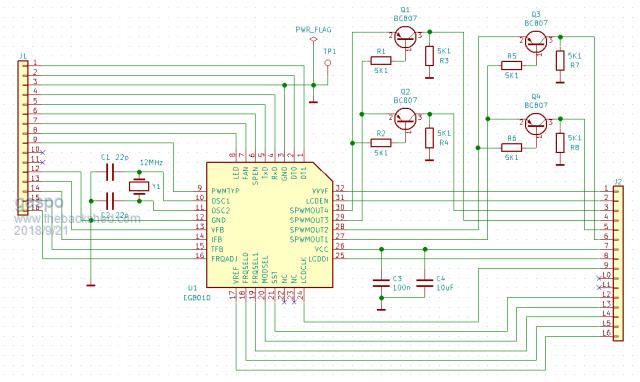 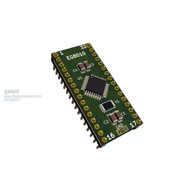 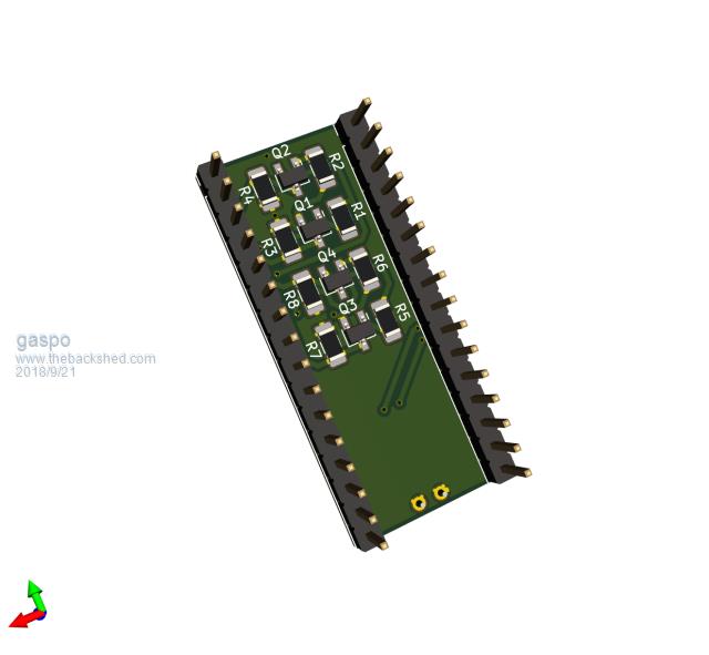 |
||||
renewableMark Guru Joined: 09/12/2017 Location: AustraliaPosts: 1678 |
Thanks for the reply Wiseguy. Gaspo!!! F hell, good work mate!! With the Mad board, the nano monitors the perimeters and does the restart as far as I know, not 100% on that though, so I'm not sure if that 8010 light blinks, never thought to look to be honest, Mad can confirm that, mine is all in a case now running the house and reluctant to fiddle with it. Only time I have noticed a light on the control board (other than solid green)was from over current, but that is a different light, that one goes solid red from memory and the (edit) GREEN one for the 8010 blinks, I did make that do it a number of times, but it needs to be left go DEAD flat to do a re start. Probably if you have an over current event you could simply disconnect the ribbon cable, power the control board with 48v and let the 8010 do a start up, clear the error (simply by restarting) and turn it off. Then re connect the ribbon and start as normal. These error shutdowns would probably be very rare if you are not trying to power an entire town. Likewise temp shutdowns wouldn't happen if it's heatsinked ok and fans are operational. Cheers Caveman Mark Off grid eastern Melb |
||||
| Warpspeed Guru Joined: 09/08/2007 Location: AustraliaPosts: 4406 |
Many factors at work here Mark, what this means is that both upper and lower mosfets (might) be turned on simultaneously for that amount of time, and even if they were the amount of actual fault current flowing is not well defined. Turning on a mosfet is not easy, there is a lot of gate capacitance to charge up, and it can take several amps per mosfet to do it really fast. Also there is a gate threshold voltage, usually about +3.5v before the thing even begins to conduct at all. It then begins to conduct and the "on" resistance starts to rapidly fall. That does not happen instantaneously either. So there can be a fairly long time interval between when the control chip output goes logic high, and the particular mosfet wakes up and starts to draw some rapidly increasing current. There is another completely independent factor. How fast the current can rise and to what value, depending on any series inductance in the power supply to the bridge circuit. The mosfet drain current cannot rise instantly even if the mosfet could turn on in zero time. There will be series inductance in the bridge circuit, and the large electrolytics also have some internal inductance. So the power souce also limits how fast things can happen. Combine all these unknown factors together and there may be a very sudden lethal event, or hardly anything at all happens as the whole bridge circuit is just too slow to fully respond. There is an irony here. If you build a really fast highly efficient circuit, its MORE likely to blow up ! On top of that there can be a gradual degradation of the mosfets if they are sufficiently stressed hundreds or thousands of times. Soft starts will not help in this particular case. Even the smallest narrowest lowest duty cycle turn on may be lethal if both upper and lower mosfets turn hard on simultaneously. So don't be too hard on us Mark. There are a handful of professional circuit designers here that take all this kind of thing very seriously. Its our bread and butter to design things that work efficiently and are long term completely reliable. Cheers, Tony. |
||||
| wiseguy Guru Joined: 21/06/2018 Location: AustraliaPosts: 1156 |
Gaspo - well done couldn't have done better myself, Im thinking you and Altium have had a long term relationship? You saved me the trouble - I was thinking about TinyT and others with poor eyesight soldering in SOT23's so I was planning to adulterate a good layout and use normal resistors and TO92's etc and a normal crystal (the resistors would all stand up like an old transistor radio of course). My dummy spit about not doing the board was at the end of a stressful day I felt differently the following morning. However after taking a cursory look at your layout I think surface mount is the way to go. My only suggestion is to provide pads for the HF bypass capacitors on the analog inputs. I havent checked the schematic and pcb for correctness but I will assume it is ok unless you ask me to check it. Obviously the schematic is the most important part to get right the rest follows if using Altium in its intended fashion. What are your suggestions of how tired old eyes and no smd devices in their toolkit that constructors could make or have access to a completed board? If at first you dont succeed, I suggest you avoid sky diving.... Cheers Mike |
||||
| wiseguy Guru Joined: 21/06/2018 Location: AustraliaPosts: 1156 |
Im with you also Poida that is why I ordered some EGS002 boards - if they can be simply tamed it is good bang for buck. (ok maybe not the best choice of words....). I bought separate EG8010 IC's as I wanted to find out what makes them tick (or louder noises) or not. I have the luxury of not needing my inverter for 6+ months so I am making time to understand it all better before I just rush in. Maybe we should have an IA group (like an AA group)for failed inveter constructors - I am one too. Some years ago I attempted a 6KW 72V Dc unit with a humongous Toroid and totally discrete circuitry. But other projects and a personal tradgedy took over before I stopped it going bang. Ok so there I admitted it my second inverter project went bang! But I am confident it was shoot through - the series choke was also missing.......which did not help. If at first you dont succeed, I suggest you avoid sky diving.... Cheers Mike |
||||
renewableMark Guru Joined: 09/12/2017 Location: AustraliaPosts: 1678 |
Fair point Tony, but I was told it doesn't work, when I know it does, I'm typing from a pc that is powered by that inverter right now. That unit has had numerous forced shutdowns from out of parameter events. Anyway enough on that, maybe someone should test the actual fets in a running machine rather than the chip itself. Cheers Caveman Mark Off grid eastern Melb |
||||
| wiseguy Guru Joined: 21/06/2018 Location: AustraliaPosts: 1156 |
Aww come on Mark lets keep it reasonably factual - lets see before you were "barking at me" (your words) I wrote: "Why dont more inverters give more grief ?" "when set up properly and then turned on, an inverter may run indefinitely" "I dont argue that when running they might continue indefinitely for most builds" That is not being told "it doesnt work" The very topic we are posting under eludes to randomness. If at first you dont succeed, I suggest you avoid sky diving.... Cheers Mike |
||||
renewableMark Guru Joined: 09/12/2017 Location: AustraliaPosts: 1678 |
I meant that mine has survived numerous shutdowns, overcurrent, under volts etc. Cheers Caveman Mark Off grid eastern Melb |
||||
| Warpspeed Guru Joined: 09/08/2007 Location: AustraliaPosts: 4406 |
There are many shades of grey between running sweetly for years and it suddenly blew up and burst into flames. Things can still be be "not quite right" and the inverter still soldiers on in a fashion. You will know yourself what a big difference adding just the right tuning capacitor across your toroiod, and fitting a REAL choke made to your own inverter. These may seem like really trivial details, but they are not. Like going to your doctor, he looks into your eyes, peers down your throat, sticks his finger up your bum, and says you need to take the green pills twice a day. You just have to trust his judgement that those green pills are really necessary. Cheers, Tony. |
||||
| gaspo Regular Member Joined: 25/06/2018 Location: AustraliaPosts: 65 |
No, its not the Altium I'm friend with. I prefer the company of KiCAD  I was thinking of using the through hole components but the board is too small to fit it all. The SMD parts I used are the normal sized 1206 with larger pads for hand soldering. These are easy to solder using the desktop magnifier lamp. I've added bypass caps for the TFB, VFB and IFB inputs. Files are attached below. 2018-09-21_142821_EG8010-adapter-files.zip |
||||
| wiseguy Guru Joined: 21/06/2018 Location: AustraliaPosts: 1156 |
Excellent update Gaspo. At first glance I cant really tell the difference between your Kicad schematic & pcb and an Altium output - I dont know Kicad - I started with Pcad. As far as a retrofit goes to eliminate cross conduction and minimise noise pick up by the crystal your updated board solves both. - could we make the vias under the xtal with hc49S spacing and un-tent them then the normal thru hole Xtal could be soldered in. If a new construction is under way the bypass capacitors are better on the module, but if it is a retrofit the ones already fitted on the main board can be used. It does not matter if both are fitted. 1 last item to consider for future proofing - if the the 5V rail has any temperature drift the output voltage will vary in proportion, as Vref is tied to the 5V rail. Could we have a TL431 (SOT23) added to EG8010 Vref with 3 resistors (values to be selected later), 1 from adj to anode (gnd) and 1 from adj to the cathode, a 100n cap from Eg8010 pin 17 Vref to Gnd. I think it will fit nicely. The third resistor is from pin 17 of the adapter PCB to the TL431 cathode, as the adaptor board Pin 17 is tied on the main control PCB to the 5V rail. For a standard retrofit we would not add the extra parts (except the capacitor). The resistor between the pin 17's can be just bridged or 0 ohms fitted, it will then be as it always was. The centre A pin is Adjust sorry 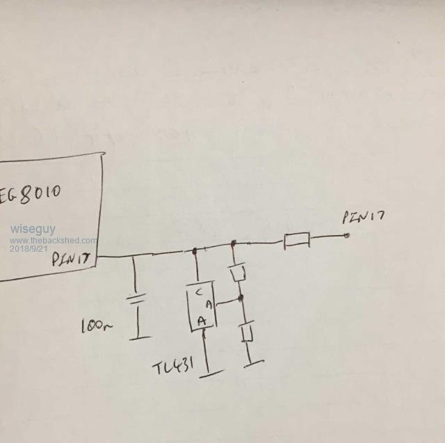 If at first you dont succeed, I suggest you avoid sky diving.... Cheers Mike |
||||