|

|
Forum Index : Electronics : 5KW Battery Charger
| Author | Message | ||||
| Solar Mike Guru Joined: 08/02/2015 Location: New ZealandPosts: 1138 |
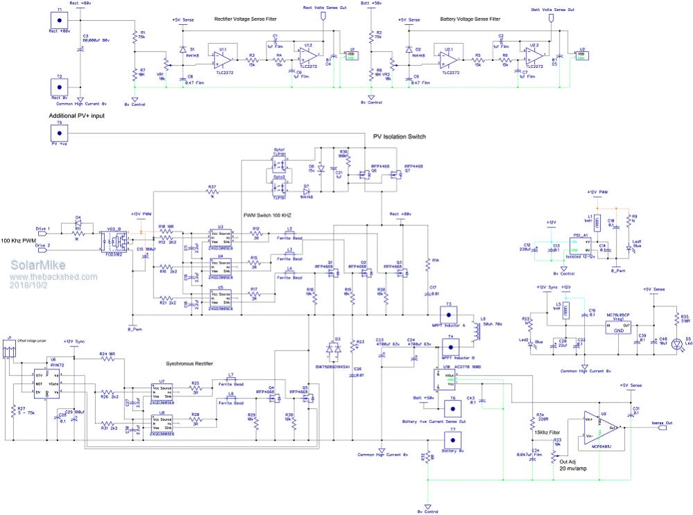
Been awhile on this project, I have ordered one of those cheap 200amp Chinese Inverter welders for around NZ$130, will add some extra turns to its output coil to up the DC voltage output. I need it to work on a 48 volt bank. Was going to use the old toroidal core I have here as a voltage source, but decided a light weight working off the shelf item would be easier. The actual charger is basically a Buck Inverter with Synchronous Rectifier, I need it to work with a small interim 24v 300 AH volt bank, then near the end of the year when all the batteries arrive and installed in a container a full 48v 900 AH bank. The small bank requires max 60 amps charge current so require current limiting. Looking around here NZ, there are no off the shelf battery chargers that work on both 24\48 volts, you can get little ones up to 20 amps or big ones 60-100 amps single voltage only for vast amounts of money; building one is the only option. Then I thought why build just a battery charger, the circuit with a little modification could be turned into a MPPT PV charge controller if driven from a PV source by adding an extra mosfet PV isolation switch, this slow switch only has to turn on when charging, other times switched off to prevent the batteries discharging into the PV array. It is driven by opto-couplers that output a voltage at very low current but enough to switch a mosfet. No modular construction this time, the complete circuit fits on a 250x150mm double sided 2oz pcb. Using 80v rated input caps currently, their voltage could be increased to allow higher PV voltages. Schematic in progress below.  2018-10-02_165901_charger.pdf Cheers Mike |
||||
| Solar Mike Guru Joined: 08/02/2015 Location: New ZealandPosts: 1138 |
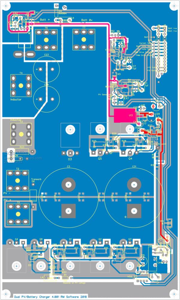
Finally completed PCB design, will make a prototype board over the next week or so and test it. Try on a low voltage 80v supply first, then unscrew the 2 input caps and replace with 200v versions to tryout as a PV controller. Power devices mount underneath the pcb bolted to a 5mm alloy panel that forms the rear of the case. The bottom of the pcb has mainly smd 1uf ceramic caps mounted around the main electrolytics. Its interesting I pulled apart a PCM60X PV controller apart today, its output caps are 100 or so smd chip ceramics mounted on a little pcb direct on the output of the buck converter coil all in parallel with a small electrolytic. Driver board with pic CPU plugs on top. 200 amp Chinese inverter welder arrived yesterday, so hopefully it can be modified to output a higher dc voltage as dc power source driven from a 4KW standby generator.  Cheers Mike |
||||