
|

|
Forum Index : Electronics : Inverter # 4
| Author | Message | ||||
| Tinker Guru Joined: 07/11/2007 Location: AustraliaPosts: 1904 |
Ring ferrite toroid and large non saturating ex aerosharp C cores. Pics in next instalment. Klaus |
||||
| tinyt Guru Joined: 12/11/2017 Location: United StatesPosts: 438 |
Very nice work Tinker. Next time I will follow the good stuff that your are showing. I notice that you use flat washer between screw head and mosfet body. On some power equipment I fixed, they also use spring washers to maintain pressure I guess during thermal expansion/contraction, will it be a good addition? |
||||
| Tinker Guru Joined: 07/11/2007 Location: AustraliaPosts: 1904 |
Tinyt, it depends how hot your Mosfets will get. I do not like the spring washer idea, this might damage the mosfet plastic body. In a really 'hot' situation perhaps copper washers might help, they also expand as they get hot. In my case the washers are for spreading the pressure only, the socket head is rather small. The screws are stainless which I think expands less than the heatsink aluminium so, hopefully, no pressure loss when hot. Temperature will not be a problem with my inverter as the heatsink seems to be plenty big enough. See my thread update today. Klaus |
||||
Madness Guru Joined: 08/10/2011 Location: AustraliaPosts: 2498 |
I use spring washers and larger flat washers to spread the load on the MOSFETs, never had any issues with that I am aware of with it. If there was any stretching of the screw threads due to expansion of the Aluminium the spring washers will keep the pressure on the MOSFETs. There are only 10 types of people in the world: those who understand binary, and those who don't. |
||||
| Tinker Guru Joined: 07/11/2007 Location: AustraliaPosts: 1904 |
There was excess solar power available today so I did an endurance test. One hour with a 2Kw load. The toroid would need a fan if it was in an enclosure with this constant load. It measured 75 degrees C at the end of the hour. I measure temperature with a non contact infrared thermometer. A little tip, I know these meters do not measure accurately off a shiny surface. So I stuck a little square of that thin, black double side heatsink tape on the enameled wires. This worked very well. By contrast my 12 Mosfets got only up to 32 degrees in that hour. The ambient shed temperature was 17 degrees, its mid winter here. More on my inverter building: There is another little PCB that deals with the AC side. 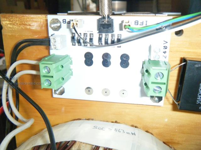 On the left are terminals for 230V AC in from the secondary and smaller terminals for the feedback winding. There is space for up to 3 x 2uF capacitors in the middle, not yet soldered in. The mains out terminals are on the right as well as two smaller 230V terminals to connect a power (V,A,W,KWh) meter. On top is a 3.5mm jack for the current transformer I bought, the blue one pictured. This proved to have too small an output (unless I wound the wire 10 times around) So I resurrected the C/T from a junked power display which had plenty of volts for the 15A test current. 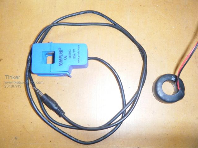 Now I had everything fitted together and ready to connect up to the battery and throw the switch. This is a bad idea which I had learned the hard way, at the cost of many blown Mosfets  . .Much better to check everything yet again and then methodically test it. Here is the schematic of the control board, I use a printed version for checking. 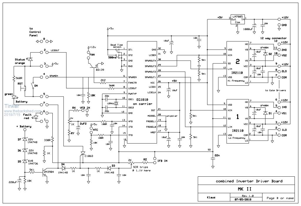 I start with powering the little DC/DC converter By itself from my adjustable bench supply. 55V DC in got 12.2V DC out, good enough for me. Pre test conditions: no IC's plugged in, no EG1810, no capacitors, no primary winding connected. Connect the 12V output to the control board, the 55V input to the pos heatsink and neg busbar. Apply 55V, perhaps via an Amp meter, and check for excessive current. There should be virtually none, just the on current of the 5V regulator. Then I check for the 12V to be where it should be as well as the 5V. If all is well now is the time to select the series resistors for the trim pots. I like to have the trim pots centered before soldering them in. With 25 turn pots an Ohm meter is easiest for that. For a 2K pot turn the little screw until 1K is measured between the center and one outer leg, its not critical BTW. I have a little special screwdriver for that, this has a collar so it won't slip off the tiny slotted head even if its in a awkward position. Got mine from RS components (check for "moulded plastic trimming tool") but perhaps nowadays available from Ebay as well. I did the VFB adjustment first. The toroid primary is connected via a switch (The toroid is NOT connected to the inverter yet) to the mains and the feedback winding to the feedback input of the AC board. Or if a separate little transformer is used, that instead of the toroid. Turn on the switch and measure how much DC is at the VFB header pins. Its not critical as long as its more than about 6V DC. No filter capacitor is used BTW. We know, from the application notes, that the EG1810 is looking for 3V DC feedback on its VFB input when the secondary is at the required AC voltage. For those unfamiliar with feedback, it works on the same principle as a governor on a genset. There it adjusts the fuel supply to keep the RPM steady for varying loads. With our inverter the feedback keeps the output voltage steady for varying loads. A load increase would drop the secondary voltage. This also drops, proportionally, the feedback voltage. The EG1810 senses that and pumps in more power to the primary to compensate. Anyway, we need a simple voltage divider to set the 1K trimpot wiper at 3V DC when there is the required AC at the secondary. So, working backwards, with a 1K trimpot its mid point sits at 3V. A 0.5V adjustment range is plenty. So, the lower end of the pot (on the schematic) sits at 3V minus 0.25V = 2.75V. The upper end sits at 3.25V in this example. Now, the measured rectified feedback voltage in my case was 16.75V. This depends on the number of feedback winding turns or little transformer rating. For my case the upper series resistor, RX, has to drop 16.75V minus 3.25V = 13.5V. The lower series resistor, RY, has to drop 2.75V. Now we need to convert that voltage drop into resistance values. The trimpot is 1K so we could call that one unit with 0.5 volts across it. RX has 13.5V/0.5V = 27 units. RY has 2.75V/0.5V = 5.5 units. With 1K being 1 unit 27 units become 27K. RX=27K 5.5 units become 5K6, the nearest standard resistor value. RY=5K6 Sorry about that tedious explanation for those for whom all that is old news, perhaps it helps some newbies. I always find it easier to check when understanding why those values are set just so. Of course, these calculated values are different for a different DC output from the feedback winding, just change the Volts across RX as required. With the VFB preset we can tackle the IFB's RZ value in similar fashion. By testing I found out at what voltage on the wiper of the IFB trimpot the SCR fires. As above, no IC's inserted etc. First I plug in the control box which contains the fault LED. Then I power up the control board (12V input), nothing should happen. From a separate adjustable (down to zero Volts) power supply its positive output is connected to the trimpot wiper (set at its mid point) and negative to ground. Gradually increasing power supply the voltage, very slowly as it approaches 1V, I watch the fault light. As soon as it comes on (the SCR has tripped) I note the voltage. Best to repeat this a few times to get a good trip voltage. This was at 1.1 Volt. Now I get my chosen current transformer and measure its output at various currents. Required for this is a 20Amp meter and a big transformer with room to squeeze in a single turn of 2mm wire or something that can handle 15 Amps. One pass through the toroid center would do as well. This wire passes through the C/T and is shorted by the Ampmeter. I feed the transformer primary from my variac and slowly increase its voltage until 5 Amps AC flow. Then note the corresponding output voltage from the C/T. Repeat for 10A AC and 15A AC on the Ampmeter. If I wanted a 30 Amp trip then I would double the 15A voltage for the RZ selection below. But not everybody has a variac so then what? Use some load in series with the primary to drop the voltage, perhaps 100W lamps might get a suitable current in the single turn. Need to experiment here. But, care is required with mains voltage connection! Also, never apply full mains voltage as the shorted single turn could get very hot and also damage the Amp meter. Another important thing, I noticed that my C/T was very suspect to magnetic fields. Its output varied a lot when it was next to the big transformer, also which way it was turned there. So, I made that single turn with a long wire which let me hang the C/T near the floor and away from the transformer on the bench. Keep this in mind when fitting the C/T in the finished inverter. It should be as far as possible away from the transformer and its primary wiring. So we know the current transformer output now. The calculations are similar but only one dropping resistor, RZ is used. In my case, 15A AC (=3450W) was chosen for the trip current. This represented 20V DC from the C/T. With the centered trimpot wiper near at enough 1V and having a 2K trimpot the RZ end of the pot sits at 2V. So 18V is to be dropped across RZ, making RZ 18K. Turning the adjustment to reduce the voltage at the trimpot wiper will increase the trip Amps and vice versa. Simple, not? With all presetting done now the testing continues. With everything turned off the EG1810 is inserted, pin 1 near the dead time selector. These I set to 300ns, DT1 & DT2 to 0V. No IR2110 chips plugged in at this stage. The control box is plugged in. The toriod (or little transformer) is connected to 230V mains input, as before, to get a VFB voltage. Its switched off but ready. The feedback winding connects to the AC board feedback input. The inverter power switch (on the switch box) is off. A CRO is required for this test, that little digital kit job works admirably for that. With 55V power applied, on my control board the low voltage sense will activate as well initially, turning on the fault light. This is reset, fault light now off. Now the inverter power switch is turned on and then the 230V switch supplying power to the toroid (or little transformer). Only a few seconds are available for the second part or the EG1810 senses no feedback and shuts down. Do not reverse that switching sequence. The EG1810 should now soft start and run. Check for the waveforms at the socket pin 10 of #1 IR2110. Be very careful with the probe tip, a slip could kill the EG1810. You know its dead when there is only a square wave, or nothing, at all tests below. 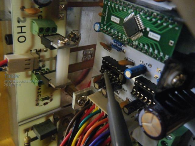 It should look like this: 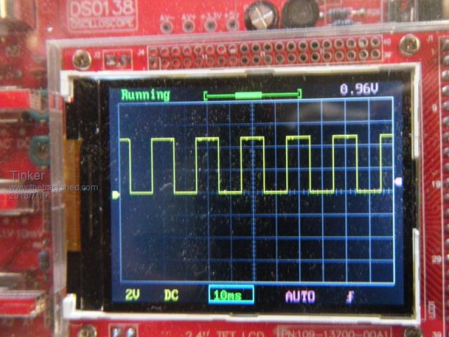 Pin 12 of same IC looks the same. Now we need the special capacitor probe shown in the EGS002 application notes. Applying that to pin 10 of #2 IR2110 we get this wave form: 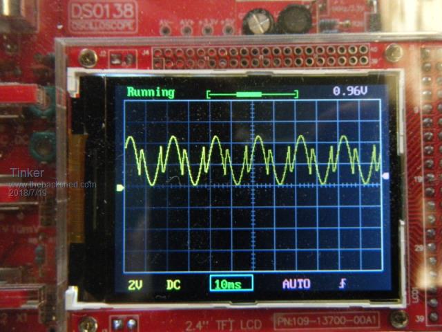 The same signal at pin 12 If OK so far switch off the AC transformer, inverter power switch and DC power. Insert the two IR2110 chips. Take care no pin folds under the chip body as its inserted. Now turn on as above. Test for driver output here on the end of the unplugged gate drive lead: 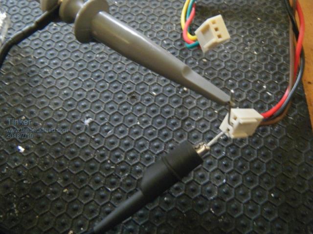 Signal at the 1LO plug: 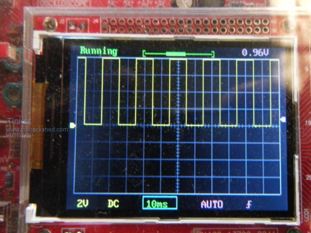 Its as before but bigger. And at at the 2LO plug: 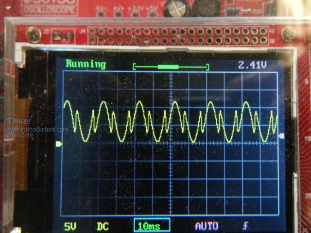 The signals at 1HO and 2HO are not available yet as they require the primary winding to be connected. The inverter is now ready for full powering up, I'll make another post for this as this one is getting too long. To be continued Klaus |
||||
| Warpspeed Guru Joined: 09/08/2007 Location: AustraliaPosts: 4406 |
Excellent writeup Klaus. This is the way to do it, very slowly one small step at a time bring the beast to life checking everything that can be checked. It involves assembling some odd pieces of special purpose test equipment so various things can be pre-adjusted and the functionality of everything verified. Cheers, Tony. |
||||
| johnmc Senior Member Joined: 21/01/2011 Location: AustraliaPosts: 282 |
Excellent description Tinker. This will be a invaluable guide for all, especially us with a electronic handicap Many thanks for your effort. Cheers john johnmc |
||||
| Tinker Guru Joined: 07/11/2007 Location: AustraliaPosts: 1904 |
Thanks for the kind comments guys, much appreciated (and makes my 4 times proof reading worthwhile)  . .Keeping in mind that two years ago I knew nothing about how an inverter works, never having to deal with one, all my knowledge about them was picked up here. Poida does an excellent job showing us how the thing works and backing it up with with very nice oscilloscope screenshots. I try to show the hands on side how to get an inverter going the first time. That was easy now but not so at the beginning  . .Its my belief that this is a project for people who have a reasonable knowledge of electrics/electronics and are willing to learn the specifics of an inverter. Its far too dangerous a project to assemble from a kit "paint by numbers" style, not knowing what the parts do. An open invitation for magic smoke IMO. So to continue my post. I should mention some common 'mistakes' that are very easy to make. One is the orientation of the little pin sockets. I use a bigger type than the ozinverter, it still has the same 0.1" pin spacing though. The make is 'oupiin, from Altronics. These have a taller socket, easier to grab hold of, and a feature I very much like. There are little 'windows' where the connector barb locks into. If the plug was wired the wrong way its easy to depress that barb with a jewelers screwdriver and pull the connector out. Bending that barb up again with a knife blade gets the connector ready to lock into the correct place. This is much easier than trying to unsolder the pin carrier if it was assembled the wrong way round. When during pre testing the inverter won't start check, after you checked the board again for solder bridges, etc., the wire connection at the VFB and IFB plugs. If the pos and neg are mixed up at VFB she will not go, If the same at IFB you can't set the SCR trip point. The other thing is a peculiarity with these green 'Dinkle' brand connectors. The wire clamping part moves up toward the screw, not the other way around as on many connectors. So what? Well unless one pushes the screw in while undoing the wire the clamp can stick halfway down. This lets one insert the wire or Mosfet leg -under- the clamp and you definitely do not want it there. The thing will jam when trying to tighten it and trap the mosfet leg. Its quite a job to free it - you can guess how I know that  . .Here is a picture of my test set up: 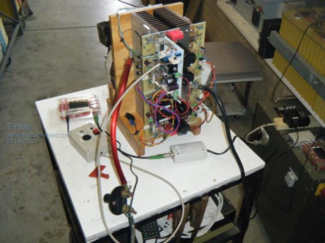 All my test were done with 4 turns for each primary leg on this ring ferrite core. 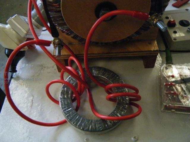 It did not seem to matter if the turns were untidy, as long as the wire went through the hole 4 times. Both coils were wound in the same direction but connected at the opposite ends to the primary. Later I experimented with fewer or more turns with a 2KW load. 3 turns at each side is still OK. The slight wiggle at zero crossing gets a little more pronounced with every extra turn above 4. I tried up to 6 turns each. That ring core is soo much more user friendly for the experimenter. I used it because I did not have an E65 ferrite core and was pleasantly surprised. Idle current test with a 0.8uF capacitor at the secondary: 0.2A and this wave form. BTW, I used a long exposure so the slight fuzzyness of the trace is camera shake. 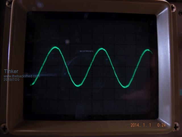 With a 1uF or a 2uF cap the idle current did not change, nor did the sine wave. A 4.8uF capacitor drew 0.22A and the sine wave straights got a little wavy. 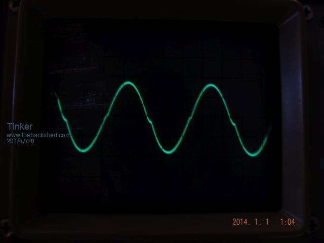 A 7.4uF cap (the black boxy type out of the Aerosharp) drew 0.27A and had a little worse wavyness. Load test with 2KW with 0.8uF cap had a small 'kink' at the zero crossing. 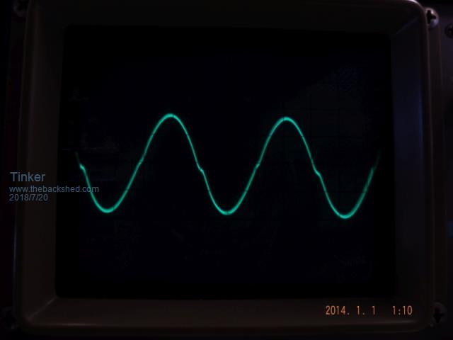 This 'kink' got more pronounced as the capacitance was increased. Here at 4.8uF. 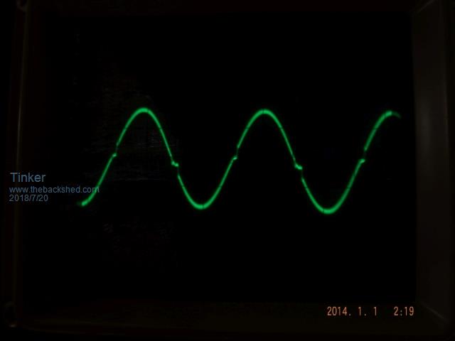 I should mention that all the load tests above had the big non saturating choke in series with one primary as well. This has 18 turns wound over doubled Aerosharp C cores, the bigger ones. To see what happens under load when it is not there look at this image. 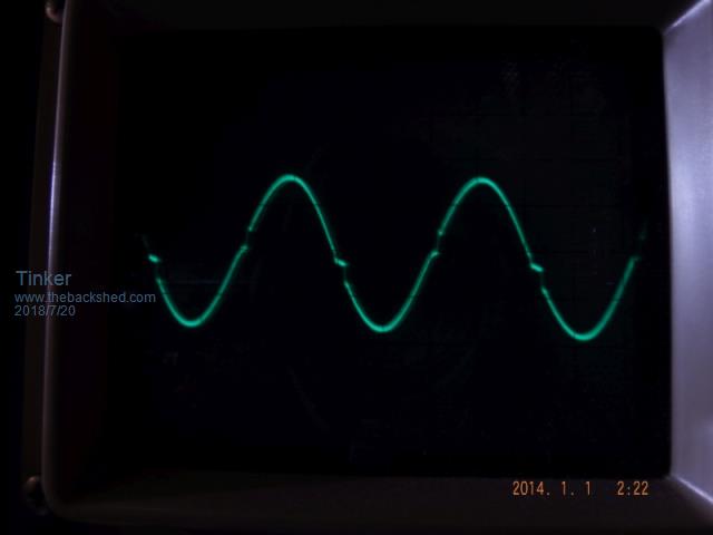 After these tests it remained to test the TFB feature. This one is easy. Unscrew the NTC Sensor from the heatsink. With the inverter running, connect a light bulb as a load, then heat the sensor with a soldering iron. Use the hot barrel of it, not the tip. At around 45 degrees the fan should turn on. Keep on heating the NTC. When its still hotter, maybe 60 degrees?, the EG1810 shuts down, the connected light goes off but the fan keeps on running. Remove the soldering iron and let the NTC sensor cool down. After a while the inverter soft starts automatically, the light turns back on and later the fan stops when the sensor has further cooled down. Quite neat this feature and its all I will use for this inverter whose heatsink size most likely never requires the fan running  . .If it were in a cabinet though, because the toroid is not very powerful compared to the 12 Mosfets, I would use a completely separate fan as well. This one could be easily controlled by one of those neat Ebay temperature controllers. The ones I use in my big inverters have a digital temperature display and lets one set many possible combinations when the fan should come on or turn off. So I will use a 2uF capacitor at the secondary now, giving me the best compromise sine wave for this toroid. I will also wind another choke to suit the single big C core I have left over. I should be able to fit 11 turns totaling 45mm sq (many wires in parallel). I have a 150 turn test coil that fits this core and tomorrow should find out the saturation figures for a single C core with the original 1.6mm air gap. Klaus |
||||
| Ralph2k6 Senior Member Joined: 24/09/2017 Location: AustraliaPosts: 129 |
Just wanted to add my thanks for writing up this tutorial/log. The details and illustrations will make this an invaluable goto guide for comparing notes and troubleshooting. Might not all be paint by numbers just yet but putting all the notes together makes the task more straightforward. I even started turning up some brass tap guides at work today (no more dodgy angle small threaded holes for me  ). ).Ralph |
||||
| wiseguy Guru Joined: 21/06/2018 Location: AustraliaPosts: 1156 |
Good work Klaus, I reckon John will be fired up again to wipe the cobwebs (and black stuff) off his inverter and have another go. You make it look all to easy - was a good read with a few trade secrets thrown in. My EGS002 boards arrived today..... finally, what with Mads advice, Im too scared to take them out of the static bags  If at first you dont succeed, I suggest you avoid sky diving.... Cheers Mike |
||||
| Tinker Guru Joined: 07/11/2007 Location: AustraliaPosts: 1904 |
Thanks, its much appreciated. Well, if you are scared tackling these temperamental EGS002 boards, I do have spare boards for the inverter described above available  . .I can even throw in the two copper bus bars for the negative rail. Klaus |
||||
| wiseguy Guru Joined: 21/06/2018 Location: AustraliaPosts: 1156 |
Thanks for the offer Klaus that's very kind - but I have also ordered some EG8010 IC's and the SMD to Dip converters, to have them available for when I decide to get really serious. I do like the sound of the copper bus bars, but like some others here, I will be rolling my own PCBs so the bus bars will probably have to be tailor made. I will start my own thread soon, but first, long before adding FETs etc I want to analyse what makes the EG8010 tick and how it functions with its supporting bits and other stimuli. Poida and some others have done some great work here - I intend to complement what they have done. Given the sketchy manual I don't totally trust it all yet. So armed with a CRO, 5V at 20mA and 12V at 20mA I shouldnt get into too much trouble to start with..... If at first you dont succeed, I suggest you avoid sky diving.... Cheers Mike |
||||
| tinyt Guru Joined: 12/11/2017 Location: United StatesPosts: 438 |
Thanks Klaus for sharing even the tiny details, calculations, and explanations. I also like your compact setup. That ring ferrite connection is new to me, is that what they call common mode choke? I wonder if a gapped ring ferrite can replace both the Exx ferrite and laminated C-core chokes. |
||||
| Warpspeed Guru Joined: 09/08/2007 Location: AustraliaPosts: 4406 |
It looks like a common mode choke, but there is one very big difference that has to do with the phasing of the two windings. A common mode choke is wound so that dc flowing around the circuit cancels out in the core, its not what we want. Current flows around the circuit start to finish in one winding, then finish to start in the other. We need a split choke that continues on around the core in the same direction, but with a break in the middle of the winding (where the primary is connected). Its very important that you get the winding directions right or the choke is not going to do anything useful. If you have any doubts about this, just build a simple choke with a single winding and connect it in series with the primary. 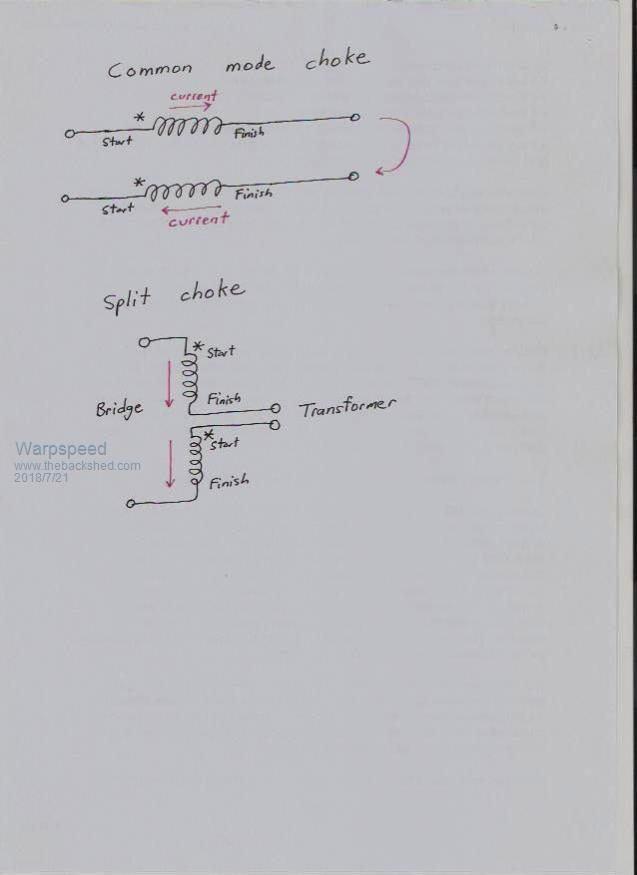 Cheers, Tony. |
||||
| Tinker Guru Joined: 07/11/2007 Location: AustraliaPosts: 1904 |
I think cutting that ferrite ring to create a gap is asking for it to break elsewhere too. Ferrite is brittle. As it is its easy to wind thick wire around it and it does the job. The inverter runs fine without an added gapped iron choke but the non saturating feature of this is very nice to have. Klaus |
||||
renewableMark Guru Joined: 09/12/2017 Location: AustraliaPosts: 1678 |
Perhaps Klaus could test that one on it's own. Cheers Caveman Mark Off grid eastern Melb |
||||
| tinyt Guru Joined: 12/11/2017 Location: United StatesPosts: 438 |
Tried cutting: 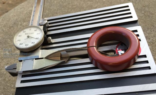 This is the saw that I used Mini saw with diamond dust blade , bought it to cut pcb. Now it has another use. Maybe after cutting, restore the structural strength by filling the gap with epoxy? The magnetic gap will still be there. 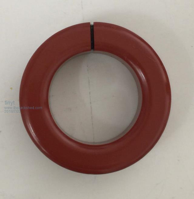 If the gap is too wide, it can be made magnetically narrower by filling it with iron filled epoxy. You can make your own proprietary mix using iron fillings or use ready made steel filled epoxy like J-B weld steel reinforced epoxy. Adding this to my testing to do list if and when I complete my inverter. |
||||
| Tinker Guru Joined: 07/11/2007 Location: AustraliaPosts: 1904 |
Yes, a diamond saw is the way to cut it - I do not have a blade like that. I think you still want two different chokes but let us know how how the one above performed. It looks a bit too small for a decent wire size. The one pictured in my post is 120mm OD, 80mm ID and 22mm high. Klaus |
||||
| gaspo Regular Member Joined: 25/06/2018 Location: AustraliaPosts: 65 |
Klaus, I'm trying to determine the number of MOSFETs needed for the reliable operation at 5-6kW. Would 16 be enough to run for an extended period (1-2 hours) at that power level? Thanks. |
||||
| Tinker Guru Joined: 07/11/2007 Location: AustraliaPosts: 1904 |
Gaspo, It depends on the size of your heatsink & cooling arrangement too. Power wise, I should say 16 HY4008's is plenty. Can't say for other types, especially the ones in smaller TO220 packages. Batches of 4 Mosfets are easier to match for as close as possible on resistance than 6 would. And if they are supposed to share the load equally they must have equal specs. I would suggest you space the mosfets at 25-30mm apart (if you make your own PCB) which requires a 250mm long heatsink for 8 mosfets. You have seen the physical arrangement of my inverter #4, the heatsink never got warm during my testing, only the undersized toroid winding. Klaus |
||||