|

|
Forum Index : Electronics : 6Kw Ozinverter build
| Author | Message | ||||
| Warpspeed Guru Joined: 09/08/2007 Location: AustraliaPosts: 4406 |
Extra wire length will certainly increase the temperature rise, but not by much. What it will do is dramatically reduce the idling power, which over 24 hours can really add up. And at night that will all be coming out of your batteries. Power lost in the windings is proportional to current squared, and it rises quite dramatically. But the mass of the transformer will absorb short term heat spikes. Below one quarter rated power, resistive heat will be only 1/16th of flat out and can be ignored. On the other hand 40 watts of constant idling power works out to 960 watt hours per day, EVERY day. And that, over time, is likely to be a much greater penalty than short bursts of heat at full flat out load. If you could get that down to 15 to 20 watts of idling power by adding extra turns, then its well worth doing. A side benefit of lowering the flux density will be a reduction in hum from the transformer. Cheers, Tony. |
||||
Madness Guru Joined: 08/10/2011 Location: AustraliaPosts: 2498 |
Is it worth doing some temporary windings to determine losses at different numbers of turns? There are only 10 types of people in the world: those who understand binary, and those who don't. |
||||
| Warpspeed Guru Joined: 09/08/2007 Location: AustraliaPosts: 4406 |
Further thoughts. With a grid tie inverter rated at 2.5Kw, it really does not matter if the transformer idling power is 50 watts. 2,550 watts in, 2,500 watts out. That loss will go completely unnoticed. Grid tie inverters do not really have idling power, they work when the sun is up, and stop working at night. With a battery powered off grid inverter the situation is entirely different. The inverter runs 24 hours, and at night that wasted idling power is like having a hole in your bucket. Now us crazies are scavenging old grid tie inverter transformers and recycling or rewinding them. Counting the original turns, and putting on a low voltage primary might seem like a good idea, and it will certainly work. But if we are stripping a toriod right down to the bare metal and starting from scratch, we can do a lot better as regards idling power than the original grid tie design. The difficulty is we don't know how good the steel in the core is. So we cannot estimate core losses because they will vary a lot depending on the particular alloy, and its heat treatment. Just about all of our recycled toroids originate from China, and they will use the cheapest crap recycled steel they can find. Results are going to vary widely. But I can tell you one thing for sure. Lowering the flux density from the original 1.5 to 1.6 Teslas to around 1.0 Tesla or less is going to make a huge difference to idling power way more than the percentage you reduce the flux density. Cheers, Tony. |
||||
| Warpspeed Guru Joined: 09/08/2007 Location: AustraliaPosts: 4406 |
Yes indeed. Just connect up your 230v winding to a variac and measure the current it draws at various applied voltages. This can be done with any number of turns, but its probably more accurate with more turns. Measure the volts per turn and work out the power in the normal way. Say 200 volts and 100mA (with 200 turns) should be the same as 20 volts and 1 amp (with only 20 turns). Same volts per turn, same power. You will quickly see that the core loss power forms a steeply rising curve. For example, you might find a 20% reduction in voltage gives a 40% reduction in power. So adding 20% more turns will have the same effect as lowering the volts per turn, and give you the same reduction in core loss. Try it and see. The improvement can be anything between quite good and astounding. The shape of the saturation curve can vary, and you don't know where you are on the curve anyway, so the results can be unpredictable. Cheers, Tony. |
||||
Madness Guru Joined: 08/10/2011 Location: AustraliaPosts: 2498 |
I don't have a variac but I do have a second inverter that I can adjust the voltage and see what the effect is. Will be a week or 2 before I have new core ready to try. I will post the results then. There are only 10 types of people in the world: those who understand binary, and those who don't. |
||||
| Warpspeed Guru Joined: 09/08/2007 Location: AustraliaPosts: 4406 |
Just for fun I took an Inspire 1.5Kw transformer which has on it only the inner primary winding. That is rated for 135 volts and has 135 turns. Hooked that up to a variac and one of those e-bay energy monitors that plugs into a power point with a three pin socket on the front to plug in whatever you are measuring. This energy monitor stopped working below 120v so I could not go lower than that. 120v 7.6 watts 130v 9.1 watts 140v 11.5 watts 150v 14.8 watts 160v 20.1 watts 170v 29.2 watts 180v 56.8 watts If we take 140v as baseline and call that 100% voltage. And we take 11.5 watts as baseline idling power and call that 100% power. If we decrease the voltage by 14% down to 120v. The idling power drops by 33% to 7.6 watts If we increase the voltage by 14% up to 160v The idling power goes up by 74% to 20.1 watts As you can see its far from linear, and the curve gets very quickly steeper in the increasing direction. Also note, the gain or drop in power is much more than the change in voltage. The exact results you get may be slightly different, but the overall characteristic will be pretty much the same. A few extra turns will drop the idling power by far more than you may be expecting. Cheers, Tony. |
||||
renewableMark Guru Joined: 09/12/2017 Location: AustraliaPosts: 1678 |
That's interesting Warpspeed, Oz's one had 114 turns, might try a few more than that. In his test in reply 3 here he said"Before you join the layers together in parallel, it is important you check that the wire turns are the same, and the phasing is correct." What is he referring to about phasing being correct? Cheers Caveman Mark Off grid eastern Melb |
||||
| Warpspeed Guru Joined: 09/08/2007 Location: AustraliaPosts: 4406 |
If you need to run three strands of thinner wire to carry the total current, as many here are doing, you will end up having three separate windings, with six free ends. Now it is vital that these three windings all have the exact same number of turns, and also that before they are connected in parallel the "phasing" is also correct. Think about connecting three 12v batteries in parallel. All three positives will be connected together, and all three negatives will be connected together. If one battery is around the wrong way, you could say its "phasing" is wrong for that battery. There will probably then be a flash and a bang, hahaha. So before you bond your three transformer windings together in parallel, you must make certain they are all go around the core in the same direction, and all the voltages are exactly the same. Its pretty difficult to stuff things up if you wind three in hand, and put all three windings on simultaneously. But you need to be a bit of an octopus to do that. If you do it one layer at a time, each layer makes the hole and the circumference slightly smaller. Each winding goes around the core a bit further and the ends of the buried windings can get hidden and maybe mixed up. So its important to make very sure things are right, before you finally solder the ends together to make it all into one winding. It all becomes a bit easier if you put some masking tape labels on the wire ends as you wind. Start 1... Finish 1 Start 2....Finish 2 etc. All the starts get tied together, and all the finishes get tied together, and the phasing will be correct. Cheers, Tony. |
||||
renewableMark Guru Joined: 09/12/2017 Location: AustraliaPosts: 1678 |
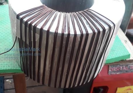
Thanks Warpspeed, the cautious side of me tells me to stick to Oz's 114, but I do like the low idle current. Now aiming for 150, if the spool runs out at 140 I'll leave it there. Here it is so far.  Cheers Caveman Mark Off grid eastern Melb |
||||
| Ralph2k6 Senior Member Joined: 24/09/2017 Location: AustraliaPosts: 129 |
Just a quick question, so if you wind the primary windings let's say 3 of together ( 3 in hand), is going to offer the same effect as winding the three wires one by one following the same pattern? Ralph |
||||
| Warpspeed Guru Joined: 09/08/2007 Location: AustraliaPosts: 4406 |
Yes, absolutely identical. One pass through the hole = one turn. Cheers, Tony. |
||||
| Ralph2k6 Senior Member Joined: 24/09/2017 Location: AustraliaPosts: 129 |
Thanks for that. I do want to make my own OZinverter some day, but for now we're getting solar installed and being paid off and it will still be cheaper to pay off due to the expected drop in power bills.. (Just gotta fit a hwc timer too) Ralph |
||||
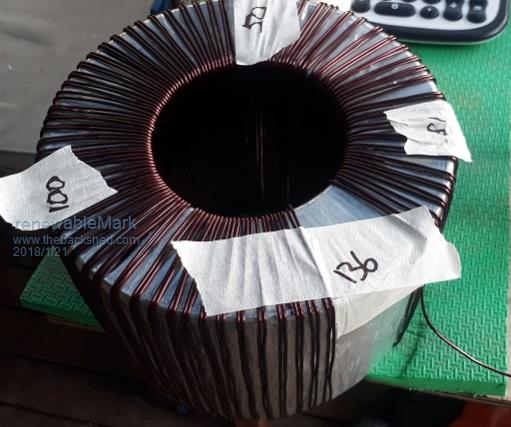
renewableMark Guru Joined: 09/12/2017 Location: AustraliaPosts: 1678 |
Well I got to 136, there is a big gap now left. I'm 50/50 whether to solder and push on or epoxy and slide those around.  the extra 14 will fit ok to get to 150. Bit worried if I decide to stop here I may not be able to slide them around evenly. Cheers Caveman Mark Off grid eastern Melb |
||||
| Warpspeed Guru Joined: 09/08/2007 Location: AustraliaPosts: 4406 |
You could probably fit on a few extra turns, but leave some gap there. The toroid hole is now very slightly smaller, and the circumference less, which means slightly less room for the next layer which must have the same number of turns. Its not much difference, but if you completely fill the first layer, you may not have sufficient room for the same number of turns on the second and third layers. One further thought, you could run that winding up to 230 volts and know even at this early stage what your idling power is likely to be. Cheers, Tony. |
||||
| Mulver Senior Member Joined: 27/02/2017 Location: AustraliaPosts: 160 |
I'd say you can probably gently, slide it around bit by bit! |
||||
renewableMark Guru Joined: 09/12/2017 Location: AustraliaPosts: 1678 |
Can you run me through that mate? (no variac) BTW got too dark to work on the deck, shed is too messy and full of crap to work in now, so I need daylight, plenty of time to ponder on it. Cheers Caveman Mark Off grid eastern Melb |
||||
Madness Guru Joined: 08/10/2011 Location: AustraliaPosts: 2498 |
Connect it to AC power and see what the current draw is. You must use a resistance such as an incandescent light bulb in series, don't connect it directly as the initial current will trip the breaker. You are going to have to do the same for the next winding any way to check urns/phase. There are only 10 types of people in the world: those who understand binary, and those who don't. |
||||
renewableMark Guru Joined: 09/12/2017 Location: AustraliaPosts: 1678 |
OK active on one and neutral on the other and clamp meter on a single line? Cheers Caveman Mark Off grid eastern Melb |
||||
Madness Guru Joined: 08/10/2011 Location: AustraliaPosts: 2498 |
Yes but don't forget the bulb, a standard multimeter will do the job too. With a 60W bulb, you won't see any more than 250 mA, you will need to measure the voltage at the windings to know how much power is being used by the core/winding resistance. To get full volts to it put a switch across the bulb, once the power is on you can close the switch. The bulb is there to limit the current at the start after that it is not needed. There are only 10 types of people in the world: those who understand binary, and those who don't. |
||||
| Warpspeed Guru Joined: 09/08/2007 Location: AustraliaPosts: 4406 |
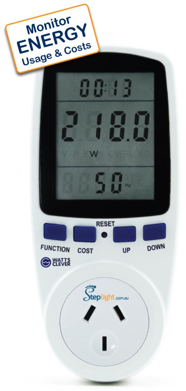
In fact the bulb test is also a very good indication of how close to core saturation you are running. If it saturates the bulb lights to full brightness (just for a moment). If there is no saturation at all, which is highly unlikely, the bulb just slowly heats up and then glows dimly. The violence of the initial turn on flash is going to be noticeably less with more turns and a lower operating flux density. Mad is quite right, with high flux density the turn on current surge can very easily trip a big breaker or blow a fuse. I have a couple of these e-bay plug in energy monitors, ideal for toroid testing, you get voltage and direct watts readout.  Cheers, Tony. |
||||