
|

|
Forum Index : Electronics : 150V 45A MPPT - roll your own
| Author | Message | ||||
| noneyabussiness Guru Joined: 31/07/2017 Location: AustraliaPosts: 513 |
Fantastic effort Peter... mine is almost at case stage... just getting caught up with life... I think it works !! |
||||
| poida Guru Joined: 02/02/2017 Location: AustraliaPosts: 1420 |
I was wondering how much power is lost from the dc-dc conversion. I assume all losses appear as heat. Most of this heat is from the diodes and MOSFETs. Some also is generated in the inductor and the PCB. I have not a lot of confidence in my current measurements. I would be happy if I could get +/- 2% accuracy. But I think it's a lot worse than that for me. How to determine the power loss in ways that do not use current measures? I thought I could see how fast the heat sink heats up, with different power sources. I can add power (or heat) sources to a heat sink and see how fast it rises in temperature. If I know the power input from one source, I could get an idea of the size of the unknown source from looking at time to change temperature. Of course temperature rise due to a constant heat source is NOT linear. It follows an exponential curve. But in parts of this curve I will call it linear because I can. And also due to it looking linear enough. Test conditions: 18 degC room temperature 110V input 1725W output The usual small heat sink mounted horizontally to reduce natural convection. A 75W heat source, also mounted on the heat sink, that can be enabled at will The temperature range test points are 45C and 50C. I have a fan that runs at 50C and switches off at 45C. The test looks like this We measure the time it takes for the heat sink to rise from 45 to 50C. Purple is temperature. Red is Vout Yellow is Iout Blue is Vin Green is Iin First is without the extra 75W, so this is the rise due to the dc-dc converter when driving 1725W output. 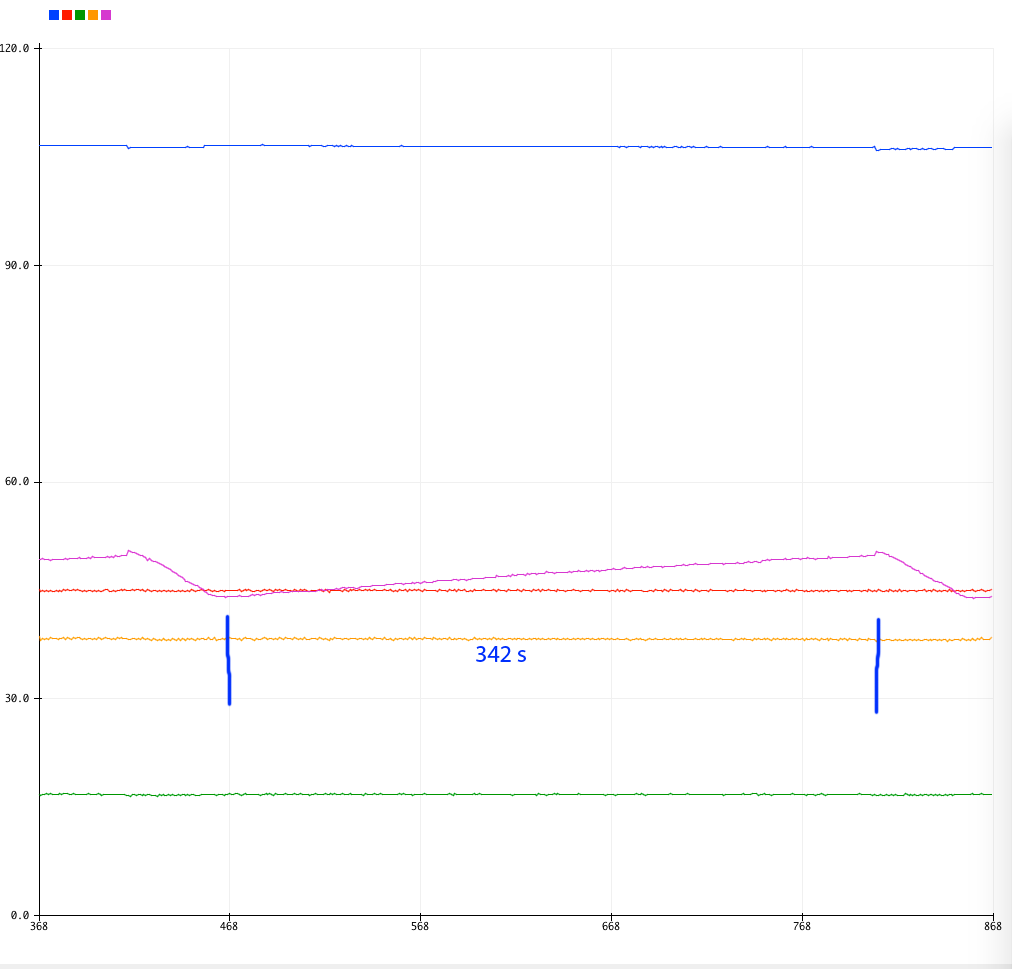 It takes 342 seconds to rise 5 deg C Now I add the 75W extra heat source. I located this heat source closer to the MOSFETS and diodes and further from the temperature sensor. This will give a fair comparison. 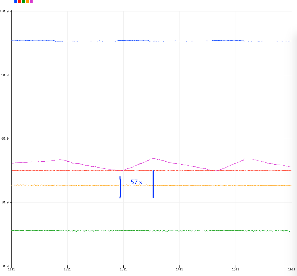 So adding only 75W makes it much faster, now it's 57 seconds to rise 5 deg C Finally here is the 75W heat source alone 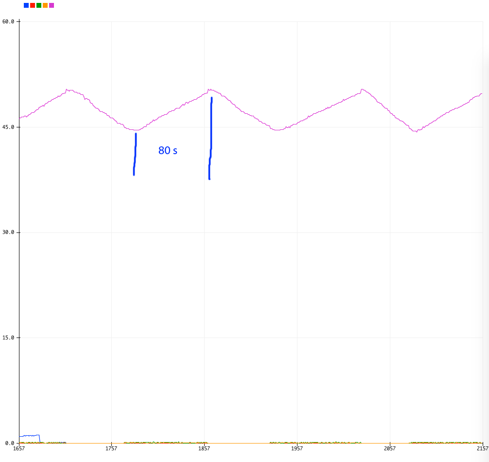 It appears that just 75W is enough to raise the temp in 80 seconds. Assuming that all this is linear (and it's not, but close enough for me with this test) I can see that to raise the temp 1 degC it's 80/5 or 16 seconds when fed 75W. A Joule is one Watt for one second. So the heat sink seems to need 16 x 75 = 1200 Joules to raise 1 deg C. Now how about when we have only the dc-dc converter running? It took 342 seconds to raise up 5 deg so it's 68 seconds per degree. What power is this? 1200 J / 68 seconds = 18 W So during this conversion (110V Input, 1725W output) there is 18W going into the heatsink. The inductor remains at room temperature, it's windings are a little warm. The PCB trace gets quite warm. I expect about the same or probably more power is lost there. I need a calorimeter and put the entire test mppt controller inside it and run tests. So this has not answered my question, which is what is the efficiency of the mppt dc-dc converter. But it has given me a much better understanding of the heat sink I am using. wronger than a phone book full of wrong phone numbers |
||||
| SYM-1 Regular Member Joined: 18/10/2019 Location: New ZealandPosts: 45 |
Well I have done the theory for a few different current settings and different windings. I can calculate the diode and fet losses from the voltage drop of the diode at certain current settings - the same for the fet. Most of my losses are in the windings of the inductor ( I assume core losses of 0). Here are some of my calculations. 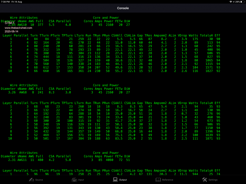 I have 45 Amps loss in the windings and about 47 Watts in the diode and fet combined using AWG10. This gives 96% efficiency. Efficiency decreases with current. Persistence is the key |
||||
| poida Guru Joined: 02/02/2017 Location: AustraliaPosts: 1420 |
SYM-1: I think 96% is as good as we can hope for. Everyone will have a different result due to using whatever parts they have. I next did a test with the heat sink vertical, to permit air flow upwards to carry away the heat. No fan. I want to see if it's possible to run this without a fan and to find out when a fan might be needed. Recall at 1725W only about 20W was put into the heat sink. I put various power into the heat sink via the 2 x IGBT DC load and let things stabilise, then took the temperature. 20W 45C 37W 52C 55W 63C 68W 69C It looks like this:  Very linear so no surprises.. I think this seemingly too small heat sink will be more than enough for my requirements which is 45A, at about 2500W. I estimate even 63C at 55W will be quite acceptable operating conditions for the MOSFETS and diodes. This 55W is well in excess of the heat produced from 2500W output. This data is for my test board. Your boards will probably differ. It's easy to do these tests. All you need is a 3kW 1 Ohm resistor and a supply good for 100V at 30 Amps. Test things and measure temperatures. To make the resistor, get some 1mm wire, galvinsed or stainless steel MIG welding wire or whatever. Take a length, measure the resistance. In the case of the stainless steel wire I use now, it was 3 lengths of 2.2m, adding up to 1.1 Ohm. I drill holes in a bit of pine board, feed the 3 lengths through making a few turns along the board. Connect the ends via nut/bolt/washers to a 4.5mm2 copper wire. Lead them up to the mppt board. Fill the bucket with water. The pine board want to float so I made a simple bracket to keep it drowned and below the surface. Some more physics: A 20 L bucket of water 4200 J/kg.C specific heat for water to take a bucket of water from 20C to 100C will need some energy. how much? (100-20) * 20 * 4200 J = 6.72E6 Joules If it's 1 ohm and you drive it at 45V , then it's also 45 Amps. This is 45 x 45 Watts = 2025 Watts 1 Joule = 1 Watt for 1 second. So we need 6.72E6 Watts for 1 second or any combo of that. We have 2025 Watts coming out of the converter so the time to 100C would be something like (within about +/- 20%) 3318 seconds or 55 minutes before boiling. I like physics. sorry if it's all a bore. wronger than a phone book full of wrong phone numbers |
||||
| nickskethisniks Guru Joined: 17/10/2017 Location: BelgiumPosts: 458 |
Peter, I would like to have all my solar/battery related components (charger/inverter/battery/etc) on a central bus in the future. Then I only need 1 usb converter on 1 RPI to connect everything. Like rs-422 for example because it is easy to convert rs232/UART to that, I can use ethernet cable or DB9 connections. That way I don't need usb-hubs and a lot of usb-->rs232 cables/converters. Are you planning to do something like that or are you staying with an individual usb-connection per device? I think I can figure it out myself, how to establish a simple setup without using something fancy/advanced like modbus or canbus etc. But I would like to know how you would handle something like this. My idea is just let the RPI sent a simple message to the device I would like to respond. example: Message: "inverter,data*" Answer could be: "inverter,25.00,26.33,15.66,13.88,23.05,28.56*" All other devices could ignore the message because message starts with inverter. BMS,MPPT1,MPPT2,MPP3 could be other devices. It would be nice to adjust parameters as well. I almost figured out your code to implement small parts of it in my BMS firmware, steep learning process... But a lot to gain and learn, thank you! Edited 2020-08-14 21:46 by nickskethisniks |
||||
| poida Guru Joined: 02/02/2017 Location: AustraliaPosts: 1420 |
I have been thinking along the same lines. A simple protocol as you suggest would be perfect. The mppt code contains easy to extend communication code. Right now, this code is listening for the character '^' If it gets this, then the next characters are read until end of line. send ^1 and you get "mppt controller v.1" send ^16 and you get the heat sink temperature. I also have this code in the nanoverter. The nanos have good and reliable support for the USB serial port. When using the Chinese cheap nanos that have the CH340 USB to serial chip things work pretty well with Mac OS and Windows. But I have found a problem with Linux (R-pi) The problem is that Linux on the R-pi can not distinguish between multiple CH340 nanos connected via USB. Not only that, the /dev/tty/USBx port numbering can alter after a reboot even when you do not change any USB plug insertions. So my logging code which was running well for weeks might fail after a power cycle because the code expects one and one only nano at /dev/tty/USB0 but this time the OS has assigned it to /dev/tty/USB1. I do not change which socket the USB plug is insterted into... Not good. So it forced me to add code so I can identify the device that is hanging off the USB port. This is a work in progress. To have many devices on the same bus rules out RS-232. The R-pi has 4 or more USB ports because we can have many devices on USB. At the moment I do not need to worry about the above issues. My system has one R-pi talking to one nano and one Morningstar MPPT controller. This nano does current sensing for 2 channels, 2 channels of digital output with one controlling the pool pump, one channel to control the inverter low voltage cut out and finally one channel for recording the street power Watt.hour pulse. The home built mppt charge controller is not connected to the R-pi but it could be in the future. I expect to have 2 home built mppt controllers, one home built inverter and the utility nano all using USB serial ports going into the R-pi. And have 2 Morningstar charge controllers unused and to be sold. Edited 2020-08-15 11:08 by poida wronger than a phone book full of wrong phone numbers |
||||
renewableMark Guru Joined: 09/12/2017 Location: AustraliaPosts: 1678 |
Hey mate, I assume the parts list was for V1. I can't find a spot for the 2x 2k2 resistors on the brainboard and the trimpot isn't on the list. What value is the trimpot? Cheers mate. Cheers Caveman Mark Off grid eastern Melb |
||||
| poida Guru Joined: 02/02/2017 Location: AustraliaPosts: 1420 |
I used a 10K trimpot but a 5K or 1K would do You only need the 2k2 resistors if you are going to use I2R LCD. I don't want to support use of the I2R any more. I want us to only use a serial type LCD which will be easy to make (just uses one more Nano) wronger than a phone book full of wrong phone numbers |
||||
| poida Guru Joined: 02/02/2017 Location: AustraliaPosts: 1420 |
Mike, I can not see any problem with running the converter at 40kHz. There is the propagation delay of course but it is frequency independent. The rise time of the switch node voltage appears identical compared with running at 20kHz. See below for tests using the TLP250. Only change is pwm frequency. the "20kHz" is of course 19,200 Hz 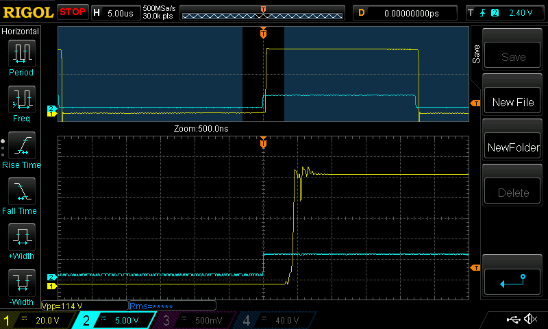 and the "40kHz" is 38,400 Hz 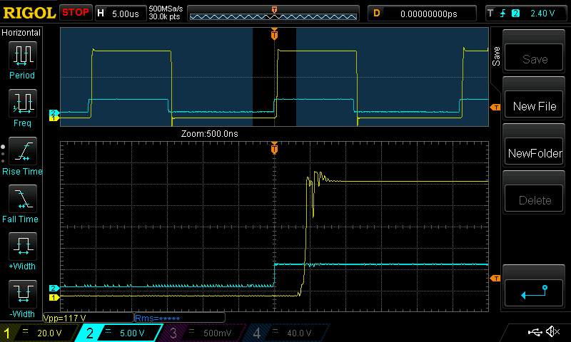 The rather untidy oscillations might be reduced with some R-C snubbing. Or smaller gate drive resistor, or a higher current drive from the FODxxx. Time to experiment. wronger than a phone book full of wrong phone numbers |
||||
renewableMark Guru Joined: 09/12/2017 Location: AustraliaPosts: 1678 |
Have you got any 3180 or 3182? I have plenty here. Also, can you run us through the serial fitting for the LCD? Edited 2020-08-17 10:01 by renewableMark Cheers Caveman Mark Off grid eastern Melb |
||||
| wiseguy Guru Joined: 21/06/2018 Location: AustraliaPosts: 1156 |
I cant see any problems running the converter at 40kHz or 80+ kHz either. This is again a case of using the manufacturers recommended operating conditions for the isolated FET driver. TLP250_datasheet_en_20190617.pdf Absolute Maximum ratings: "Operating frequency (Note 3) f 25 kHz" As previously stated, devices will often work outside of the maximum and recommended values. How long or reliably they will continue to work, with drift ageing etc taken into account is the issue. I always try to work within the manufacturers recommended datasheet values to minimise problems down the track. It is also good practice for constructors to get used to looking at datasheets if considering using a substitute part from the parts bin or/and asking the forum for advice if unsure. I am also guilty of exceeding manufacturers recommendations at times, but I do so at my own peril. I wouldn't knowingly advocate this approach for a project though. Keep up the good work Peter there's a lot to like about your MPPT project & software. If at first you dont succeed, I suggest you avoid sky diving.... Cheers Mike |
||||
| poida Guru Joined: 02/02/2017 Location: AustraliaPosts: 1420 |
Mike, of course you are correct. You know my approach is test it and if doesn't break, test it harder. I have already forgotten my error with drive current for the emitter of this part. You have pointed be back, more one once, to the specs that showed how it must be driven for reliable service. Mark: don't forget I have a shopping bag full of inductors here, that you left me to test. I think you probably want them now. How to get from A to B without getting stopped by the nice policemen.. I have no reason to be up your way, and you have no reason to be down here. Is there a supermarket 5km both from my home and your home? wronger than a phone book full of wrong phone numbers |
||||
renewableMark Guru Joined: 09/12/2017 Location: AustraliaPosts: 1678 |
No worries, I'll arrange an interparcel courier. Cheers Caveman Mark Off grid eastern Melb |
||||
| poida Guru Joined: 02/02/2017 Location: AustraliaPosts: 1420 |
to make a serial LCD: You need a 20x4 LCD, a nano and a few bits of different coloured hookup wire. If the LCD includes the I2C converter, then it's easier, only 4 wires to the LCD and 3 wires to the mppt. If no I2C, then it's 8 wires from nano to LCD and 3 wires to the mppt. I have built both types, and there is no preference for either. No I2C type: 3 wires soldered to 5V pin, Ground and D4. These could be twisted together and make them 1 foot long. Put a 3 pin connector on it so you can easily insert it. Note well which is ground and which is 5V. I would use Red, black and white for this. On the LCD we need to give 4 bits of data, the enable, the read strobe and 5V and ground. The datasheet for the 20x4 LCD modules show the pinout. there are 16 pins. We need only 1/2 of these. 1 = ground 2 = 5V 4 = register select, this is driven by the Nano when writing data 5 = Read/Write, we connect this to ground, for write only. 6 = enable 11 = data 12 = data 13 = data 14 = data pin 3 needs some care, some LCD require a voltage between 0 and 5V to give good contrast via a trimpot, others can be to ground, or to 5V. Your module will differ from mine. The one pictured needs it to ground. The nano LCD library knows 6 pins need to connected, it only wants to know which data pins are connected to what LCD pins. I have chosen: Nano D12 - register select, pin 4 Nano D11 - enable, pin 6 Nano D7 - data bit 4, pin 11 Nano D8 - data bit 5, pin 12 Nano D9 - data bit 6, pin 13 Nano D10- data bit 7, pin 14 And 5V and Ground, with two links from ground to pin5 and pin3 on the LCD. code specific for serial to LCD using the above wiring nano_serial_to_parallel_LCD_2.ino.zip Here is how I did it with one of the Wavegat boards you gave me. White is serial data, Green is ground, Yellow is 5V, all leading off bottom right. 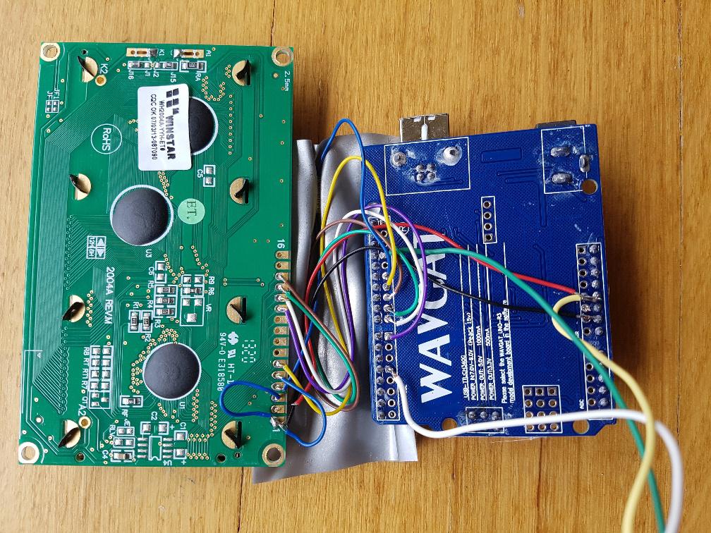 When using an LCD module with I2C, it's far simpler. connect the 3 wires as above, 5V, ground and D4. Then connect the I2C interfaces together, 4 wires. It should be easy. Nano A4 = SDA Nano A5 = SCL 5V and ground.. Then use the below code to run it. You will need to know the I2C address of the LCD module and alter the program to suit. nano_serial_to_i2c_LCD.ino.zip Both programs use the same trival protocol. 9600 baud every character sent is printed in turn on the LCD. If "$" is sent, move cursor to top left corner. That is all we need for the mppt and the nanoverter. If it all goes well, once this gets 5V, you will see this 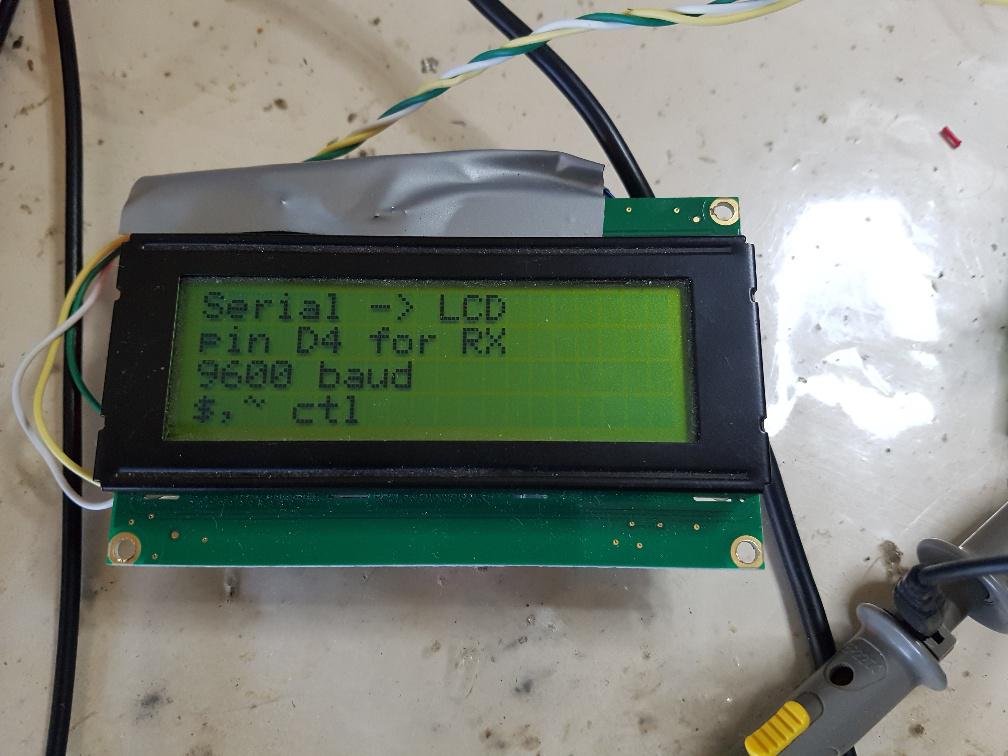 Edited 2020-08-17 15:05 by poida wronger than a phone book full of wrong phone numbers |
||||
| noneyabussiness Guru Joined: 31/07/2017 Location: AustraliaPosts: 513 |
On the tlp250 issue, the tlp 350 is literally pin for pin the same, with the same input / output current etc... but will happily run up to 50khz Attached is a pic from datasheet.. 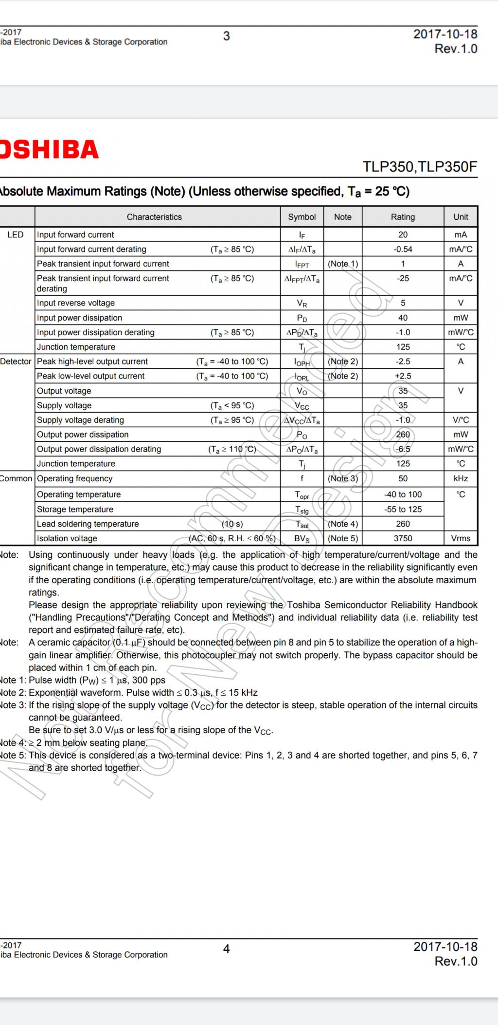 I think it works !! |
||||
| wiseguy Guru Joined: 21/06/2018 Location: AustraliaPosts: 1156 |
I am using a bit of copper bar to link the FET's with the diode and a bit of copper bar to link the diode with the shunts. This is more a thought experiment at the moment but I am getting some copper bar. What are the implications for stray inductance? Any suggestions for improvement? Having a bit more time to think about possible suggestions and in the spirit of advice to others considering your suggested approach - my advice would be don't do it ! If you have a few of those FETs & a fast diode in your parts bin well ok go ahead and use them but I would use a better gate driver (FOD3182) & preferably buffer the output. The IXFNs are a lot stiffer to drive (4x) gate charge than the FDH's. Mosfets have moved on since the creation of those wonderful SOT227 packaged parts of which I have used many hundreds. In comparison, the FDH055N15A which although looks flimsy by comparison, it will give the SOT227 some serious competition. I did the following for my own purposes just to see and decided to share the information. Main specs of interest to me were.... IXFN106N20 FDH055N15A Comment Continuous ID @ 25 Deg 106A 156A 50% more Max pulsed ID 424A 668A 57% more RDS on Max 20mOhm 5.9mOhm 338% less Gate charge 380nC 92nC 413% less MAX Power 520W 429W 121% less Avalanche Energy withstand 30mJ 835mJ 2,780% more Sorry for the previous poor formatting - I pressed update instead of preview..... With regard to Max package dissipation of nearly 100W less, the FDH part passing 156A will create ~ 144W of heat, the IXFN @ 106A will create 224W of heat. For the layman, when passing 50% more current the FDH T0247 device runs at nearly half the temperature, is 4 times easier to drive and can swallow a shipload more abuse from inductive glitches. Even if you need the extra 50V of the IXFN part there will still be a better T0247 part available. Lastly when you consider that you can buy nearly 4 FDH's for 1 IXFN, I know where I would rather put my money. Edited 2020-08-19 12:39 by wiseguy If at first you dont succeed, I suggest you avoid sky diving.... Cheers Mike |
||||
| SYM-1 Regular Member Joined: 18/10/2019 Location: New ZealandPosts: 45 |
I have already pretty well built the module. I have been a bit slow to finish it off. However I will also build a module with the FDH055N15A. The reason I built it in the first place is that I was having trouble with the TO220 FET I was using - even though it had great specs. The SOT227 does have some advantages and some disadvantages. Heat and Temperature Pro Firstly there is lead resistance. The leads on the SOT227 will take 200A continuously whereas the leads on the TO247 will only take 45A. I like things that don't get hot. Con While we are talking about heat - the SOT227 device does produce more of it - say 3 1/2 times more but in my case this will not lead to temperature rise because I am using a massive heat sink. However the wasted heat does reduce the efficiency. Stray inductance Pro There are two sources of stray inductance to worry about. The stray inductance of the device and the stray inductance of the connectors. The leads on the SOT227 device are more massive so lead inductance is much less of a problem. Also they offer a convenient way to attach my massive copper inductors. The copper bar is 10mm thick. I think there will be minimal inductance in the connectors. Con From what you say the SOT227 device need a higher current drive. This will lead to more stray inductance and it seems I will need a powerful gate driver. How many devices do we need to carry - say 85Amps. I want the be able to carry 85 Amps continuously. This is mainly because I want it to be bullet proof. In theory I could use one device but because of the high on resistance I want to use at least two. I think this means they will be pretty unstressed even at 85A - that is 42.5 Amps each so I2R for the on resistance is 36W. I like the 200V headroom too - just to make it indestructible. Mainly though I wanted to try something a bit different and I had the components on hand. I certainly would not expect most people to take my path. I am a bit worried that some have had a bad experience with IXFN devices and I am not sure how that Avalanche Energy affects the vulnerability of the device but I have gone too far down this track to not try it out. Good work on the project Mike. Great documentation of both good points and bad. I have learnt a great deal. Persistence is the key |
||||
| wiseguy Guru Joined: 21/06/2018 Location: AustraliaPosts: 1156 |
SYM1, that is 1 serious bit of engineering - if there was a construction prize I would nominate you for it ! Tinker who we don't see much of here anymore also did wonderful mechanical assemblies & I know he would be very impressed with your implementation. Someone said my Eltek frame was explosion proof - your creation then would be nuclear proof. I hope it performs as well as it looks - stray resistance inductance etc would be nigh on immeasurable. How did you go tapping the copper ? - I have broken more than a few taps doing that. Last time we electrically burnt out the tap to save re-drilling and tapping 63 other holes ! Im not sure where your 45A max for the T0247 leads comes from ? The resistivity of 1cm of lead 1.17 x 0.51mm is 0.00028 Ohms and at 100A causes ~ 2.8 watts of heat. If you can insert the legs fully and solder the devices including the wider shoulders it would be much better again. The site I used for the calculator is here I also like things to run as cool as possible, higher efficiency = less stress, less heat, less current > longer life. If at first you dont succeed, I suggest you avoid sky diving.... Cheers Mike |
||||
| ryanm Senior Member Joined: 25/09/2015 Location: AustraliaPosts: 202 |
It looks like it's going to unfold with clockwork and there's an ancient manuscript inside... |
||||
| SYM-1 Regular Member Joined: 18/10/2019 Location: New ZealandPosts: 45 |
None of the holes are tapped. The SOT227's are 13mm high so a nut fits easily underneath. I haven't tried to tap copper. I have some trouble with aluminium at 3mm. 4mm is OK. A bit of cutting fluid helps. I found the copper interesting to drill. I ended up drilling a small hole (4mm) and then increasing the size. That was much easier. Some of the holes are 8mm. I can't vouch for the voracity of the 45A. It is just something I read on the web in a comparison between SOT227 and TO247. I am sure either will do the job OK though. Good idea going back to first principles with the lead calculation. I get 0.37mOhm for your lead calculation. I am using a formula resistance = length * 22/CSA. CSA is cross sectional area. I found that formula on the net but haven't verified it from first principles. The result is pretty close to your result. Persistence is the key |
||||