|

|
Forum Index : Electronics : 6Kw Ozinverter build
| Author | Message | ||||
| tinyt Guru Joined: 12/11/2017 Location: United StatesPosts: 438 |
1200 watts current draw at 228 v(rms): 1200 / 228 = 5.26 A(rms) Peak current draw: 5.26 x 1.414 = 7.44A Using the magic ratio of 9:1, 7.44 x 9 = 67 amps peak battery draw. If the 20Ah battery cannot supply this, the expected 48 Vdc input voltage will become low, the inverter will be starved. Maybe the mosfet drive voltage became low and Rdson went up and overheated the mosfet silicon, causing the high speed avalanche failure. Just my opinion. |
||||
renewableMark Guru Joined: 09/12/2017 Location: AustraliaPosts: 1678 |
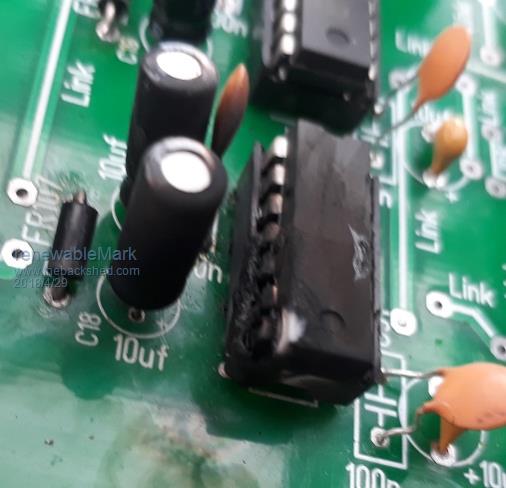
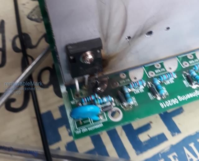
Yes, I think you are right mate. I spoke to Mad and he said the same thing. I remember OZ writing about a similar catastrophic failure which was his only one where the battery got Waaaaaay down and it sounds like it did the same thing. Anyway, I just finished rebuilding it, new diodes and resistors, fets, control board got caps mono, electrolytic and FR107's. Need to get some 14 pin sockets from a reputable local supplier, the ebay china sourced ones look a tad flimsy, not sure if they were a problem, but may as well see if there is something a tad better made. So I just need the sockets and wait for the new 2110's to arrive, then I can test again. This time I'll hook it up to the forklift battery. Cheers Caveman Mark Off grid eastern Melb |
||||
| Clockmanfr Guru Joined: 23/10/2015 Location: FrancePosts: 429 |
Yes, low voltage shut down on its own is not good, and damage will happen. I have 46v as my low voltage shutdown, set with a 5 second delay. I use the spare Overtemp connection on the control board, close the circuit and the Inverter shuts down safely. For testing I use 4 x 12v 20ah SLA batteries, and a 100w light bulb ONLY. It is important to monitor the battery voltage, and even with a 100w 230v bulb its scary watching the battery voltage drop. Mark, were you monitoring the battery voltage,? what did it get down to before it blew? I do not have the balls to try it. Everything is possible, just give me time. 3 HughP's 3.7m Wind T's (14 years). 5kW PV on 3 Trackers, (10 yrs). 21kW PV AC coupled SH GTI's. OzInverter created Grid. 1300ah 48v. |
||||
renewableMark Guru Joined: 09/12/2017 Location: AustraliaPosts: 1678 |
Well, I sure ain't going to try it again to tell you what the voltage gets down to. I wasn't watching that to be honest. Clamp meter was at 0-20 range and it went off the scale, then BANG and fire!! Cheers Caveman Mark Off grid eastern Melb |
||||
Madness Guru Joined: 08/10/2011 Location: AustraliaPosts: 2498 |
Just another learning experience, if everything went smoothly little would be learnt. There are only 10 types of people in the world: those who understand binary, and those who don't. |
||||
renewableMark Guru Joined: 09/12/2017 Location: AustraliaPosts: 1678 |
Well I suppose I can take comfort in the fact it did run the blowheater on setting 1 which would be 1000w, it was pumping out heat just as you would expect it to from a power point. So it probably would have been fine if it was hooked up to the fork battery. I see jaycar have a machined ic socket, opposed to the pressed die stamped one. I'll get those and fit the 2110's and test again. Caps are off atm so I can start again with control board testing first then power board added, then caps added. Bugger it was so close. Cheers Caveman Mark Off grid eastern Melb |
||||
Madness Guru Joined: 08/10/2011 Location: AustraliaPosts: 2498 |
Mark those machined sockets are intended for ICs with round pins, just stick to the style you have now. There are only 10 types of people in the world: those who understand binary, and those who don't. |
||||
| Tinker Guru Joined: 07/11/2007 Location: AustraliaPosts: 1904 |
I'm not sure if those machined IC sockets are the answer for you. I tried them, its ever so easy to bend one IC pin invisibly under the body while inserting the chip. Those sockets are virginal on the chip pins  . .In my case, I have re-used the cheaper type IC socket (bought fro Altronics) a few times with no issue. Just need checking that all pin inserts are down in the holder and not excessively opened up before soldering. Mark, anything you plug in that starts up slowly when it should not is a warning: do NOT persevere  , destruction *will* follow , destruction *will* follow  . .You really should fit a low voltage shut down if you continue testing with small batteries. I posted a schematic for a very simple one a while back when Madness was looking for ideas. Its easily branched into the SCR over current shut down on your board and only uses a few cheap components. Alternatively, you can do away with those batteries altogether and use a voltage booster to up the voltage from a 12V/10A power supply. This is what I do. If I overload that there is no voltage sag, instead a 10A fuse blows and everything just shuts down safely. I did describe this booster (not expensive from e-bay) a year or so ago here. There are possibly different versions around now, get one rated 10A with voltage and current controls. I put mine into a small diecast box with outside pot controls and binding posts for input & output. Turned out a very useful addition to my test gear. Klaus |
||||
renewableMark Guru Joined: 09/12/2017 Location: AustraliaPosts: 1678 |
  Thanks, Klaus, I'll just use my forklift battery from now on. I do need a low voltage disconnect though, but I think Mads new boards have that, so no need for me to try and damage my brain any more than I have with confusing stuff. At least I am documenting how not to do it and this is what happens when you do.    Cheers Caveman Mark Off grid eastern Melb |
||||
| Tinker Guru Joined: 07/11/2007 Location: AustraliaPosts: 1904 |
So we can look forward for much more spectacular bangs    Klaus |
||||
renewableMark Guru Joined: 09/12/2017 Location: AustraliaPosts: 1678 |
Well I'm going to give these boards one maybe two more goes, depends on how long the new boards take tbh. If they were here now I'd toss these. The totem pole design Mad came up with is by all accounts a much better design, considering they will not be far off I am not going to persevere with these if problems keep arising. However, that being said it also appears all my issues were self-inflicted and in fact not a fault of the boards. But if the new ones arrive before I sort this out I'll naturally work with the updated superior design boards, it would be silly not to. I'm hoping my next test will go well and I can put 16 fets on. Even if this all goes to plan it will still end up as the reserve unit, I have two more torroids, so I'll do another complete unit, that will be the Madinverter which will be the primary unit, as it has all the extra features. Cheers Caveman Mark Off grid eastern Melb |
||||
| Tinker Guru Joined: 07/11/2007 Location: AustraliaPosts: 1904 |
Mark, FYI here is where we were first shown that totem pole driver idea: driver We have to thank Solar Mike for getting our inverters working reliable with that driver. Klaus |
||||
| tinyt Guru Joined: 12/11/2017 Location: United StatesPosts: 438 |
Looking at the pictures, if re-using the PCB, inspect it and make sure there are no burned-open copper traces and scrape off any carbonized fiberglass. |
||||
renewableMark Guru Joined: 09/12/2017 Location: AustraliaPosts: 1678 |
Yeah, thanks mate, already done, carbon conducts too! Cheers Caveman Mark Off grid eastern Melb |
||||
renewableMark Guru Joined: 09/12/2017 Location: AustraliaPosts: 1678 |
We have to thank Solar Mike for getting our inverters working reliable with that driver. Yes ideas are great but they still need to be implemented. I certainly couldn't have done it. Cheers Caveman Mark Off grid eastern Melb |
||||
renewableMark Guru Joined: 09/12/2017 Location: AustraliaPosts: 1678 |
OK tested again top 2110 pins 10 and 12 give square wave, pin 1 nothing, does that indicate a possible faulty 8010? Cheers Caveman Mark Off grid eastern Melb |
||||
Madness Guru Joined: 08/10/2011 Location: AustraliaPosts: 2498 |
10 & 12 are the inputs to the IR2110 coming from the EG8010 so that would indicate the 8010 is working. There are only 10 types of people in the world: those who understand binary, and those who don't. |
||||
renewableMark Guru Joined: 09/12/2017 Location: AustraliaPosts: 1678 |
left tip 35 is fried. Thanks for the reply. Ran out of tip 35's, no more updates tonight.  Cheers Caveman Mark Off grid eastern Melb |
||||
Madness Guru Joined: 08/10/2011 Location: AustraliaPosts: 2498 |
Fried Tips and smoking chips or should that be the other way round? There are only 10 types of people in the world: those who understand binary, and those who don't. |
||||
renewableMark Guru Joined: 09/12/2017 Location: AustraliaPosts: 1678 |
Hmmm control board was a lot more rooted than I first thought. Popped 2 sets of 2110's attempting to get it going. Zener diodes tip35's various caps were rooted. I'm pretty sure it will be ok when new chips arrive. Been tempted to buy a scope like this but will only use it once or twice. If you ever have a big fry up I suggest to just do a complete rebuild of the board. I'm still not 100% sure it's right. Most parts replaced, seems to test voltages through ok. Right two pins of fets measure 7-8mohm with ribbon cable not connected, but 3.5m ohm when it is connected, that is with 2110 and 8010 board removed. I'm feeling that's not right, I'm suspecting I'll have to replace everything I haven't since the big fry. Feels like banging my head against a wall considering new boards are coming. Desoldering and burning components messes up a board, thes ones are looking pretty worse for wear now. Cheers Caveman Mark Off grid eastern Melb |
||||