
|

|
Forum Index : Electronics : 150V 45A MPPT - roll your own
| Author | Message | ||||
| Warpspeed Guru Joined: 09/08/2007 Location: AustraliaPosts: 4406 |
Nevertheless, that is how its done commercially using heavy rectangular copper wire. Each individual turn is hammered flat and into position as the bobbin is rotated each quarter turn. Note this guys really pretty orange hammer, and he is really swinging it too.  Multilayer windings are going to be much more difficult with a toroid because each successive layer has a smaller circumference, so fewer turns will fit on each layer. Not trying to irritate you with all this negativity, but I used to have a transformer winding business. Still have a couple of rubber hammers from back in those days. Cheers, Tony. |
||||
| nickskethisniks Guru Joined: 17/10/2017 Location: BelgiumPosts: 458 |
I would try to wind them simultaneously so they each have the same resistance. |
||||
| gigabyte091 Newbie Joined: 15/10/2018 Location: CroatiaPosts: 17 |
poida, i'm having a problem with software, i can't get display and serial to work... I'm using nano, and I2C LCD adapter with PCF8574T. SDA is connected to pin A4 and SCL to pin A5. I tried all I2C addresses and nothing... |
||||
| disco4now Guru Joined: 18/12/2014 Location: AustraliaPosts: 899 |
I found the PCF8574T to have address 0x27 if A0,A1,A2 are high PCF8574A is at 0x3f if A0,A1,A2 are high I adjusted code as below //PCF8574 address is 0x20--> 0x27 //PCF8574A address is 0x38--> 0x3F //LiquidCrystal_PCF8574 lcd(0x3f); //PCF8574A with A0,A1,A2 high LiquidCrystal_PCF8574 lcd(0x27); //PCF8574 with A0,A1,A2 high Also, the spare v1 brain board is good for mounting the display nano, I2C is wired and has pullups, just need to run a wire on the back for D11 for Rx. 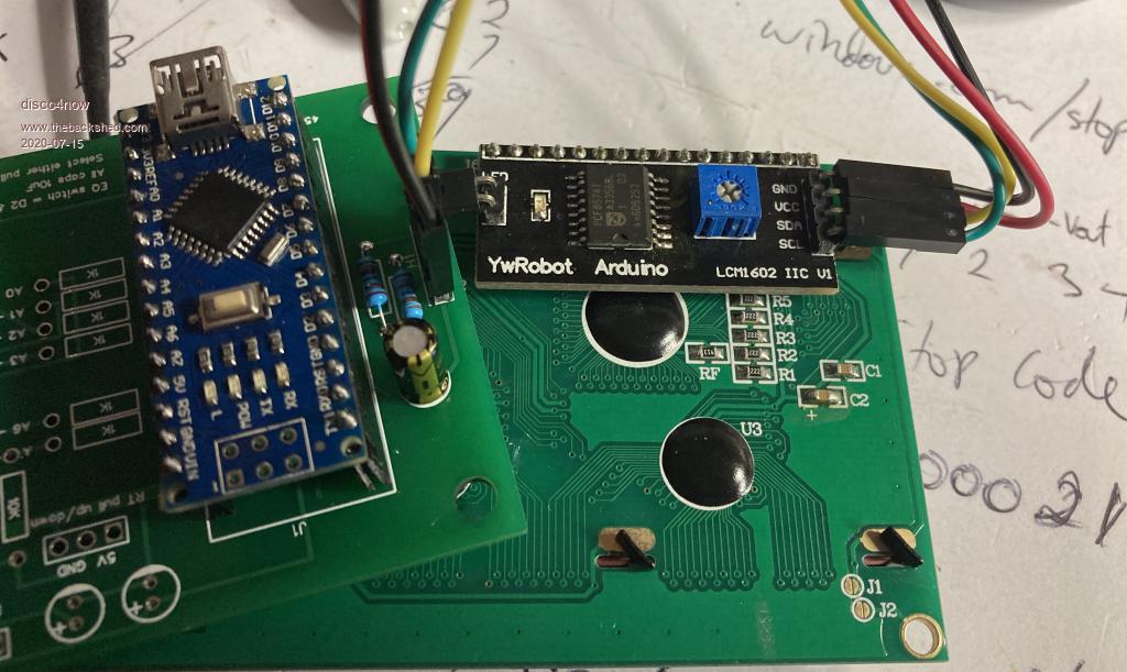 Gerry Edited 2020-07-15 18:05 by disco4now Latest F4 Latest H7 |
||||
| gigabyte091 Newbie Joined: 15/10/2018 Location: CroatiaPosts: 17 |
Which pins are used for LCD ? |
||||
| poida Guru Joined: 02/02/2017 Location: AustraliaPosts: 1420 |
I can't quite recall which version I last posted here. I suspect there is a risk I have lead us up the wrong path. I have chosen to only support serial port interface for the LCD. Why? I find that the I2C interface on the Nano (and Uno etc) is susceptible to noise and this can be so bad as to force random reboots and lockups. So I moved to a simple 9600 baud serial interface. This is rock solid. I find that when I used the "SoftwareSerial" library, the timing of things was messed up by about 20%. This had my so-called "1 minute delay" actually being 73 seconds. I suspect using the Wire library will also stuff timing up royally. The brainboard code does not use any library when running the mppt and so it runs in a very predictable manner. The latest code for the brainboard, which I have used for 2 weeks now is this: mpptv4_24-6-20_NTC_works_well.zip It requires you have yet another Nano connected to a 20 x 4 LCD. This Nano needs to run the below code. one flavor is for when you connect a Nano directly to a 20x4 LCD nano_serial_to_parallel_LCD_2.ino.zip the other version is when you connect the Nano to a I2C type 20x4 LCD nano_serial_to_i2c_LCD.ino.zip Of course we will need to know the I2C address of the LCD. Some LCDs use different addresses. Experiment. If using the I2C LCD, I use the LiquidCrystal_PCF8574 library so you will need to install that. Or use some other library if you want. The above code is trivial to modify. All the nano to LCD code does is listen for incoming data on a particular pin and then show that data on the LCD. The wiring is not too bad to do. Look in the code to see which wire goes where. The I2C code has serial data in coming into pin D10 The LCD/nano code that does not have I2C has data coming in on pin D4 and the wiring going to the LCD is LiquidCrystal lcd(12, 11, 10,9,8,7); //LiquidCrystal lcd(rs, en, d4, d5, d6, d7); plus ground, 5V and the backlight if you need it. The brainboard when running the above "NTC_works_well" version sends the LCD data out pin A4 on the 4 pin header. All you need to drive a "serial" LCD is 5V, ground and this pin, A4. Data coming out of this is 8 bits, 1 stop bit, 9600 baud. The brainboard's firmware sends out all 80 characters of the LCD data in sequence, and when it gets to the end, it sends the character '$' which the Nano/LCD interprets as "move the cursor to the top left position". And then the 80 characters are sent again. I have both I2C/Nano serial LCDs and straight Nano to LCD things. Both work fine. The wiring for the LCD Nanos is simple, look at the code and it will tell you which pin is used for serial data input. Anyone can change this simple code to use a different pin as data input. This weekend I will complete building a Wiseguy powerboard and I will show how it all goes together. A simple test setup might be first assemble a brainboard, then make the LCD/Nano. Load the corresponding firmware into both. Hook up the 3 wires from the brainboard to the LCD/nano. Give the brainboard 12V supply. It probably won't work if you power the brainboard only via the USB socket. Not enough current is there to power the LCD/nano. So give the brainboard 12V. You should see the LCD fire up and start showing the mppt firmware output data even though it's not running. Please have a look as the brainboard firmware, and make sure the "#define" for the NTC type is correct for your powerboard. There are two choices. #define HI_LOW 0 // = 1 if the NTC thermistors are connected to 5V, = 0 if they are connected to GND In my case, using Nick's powerboards, I need HI_LOW set to 0 In the case of using Wiseguy's powerboards, we will need HI_LOW set to 1 Ensure you have the correct jumper set on the brainboard to suit the NTC wiring. This setting defines how the mathematics of converting the NTC thermistor voltages will be executed. (NTC on the high side or the low side of the voltage divider) I expect to make zero change to the LCD/nano part of the project. So once you get it working, it will be done and we can forget about it. There could be changes made to the brainboard firmware in the future and that will not present any problems for us as far as I can see. wronger than a phone book full of wrong phone numbers |
||||
| noneyabussiness Guru Joined: 31/07/2017 Location: AustraliaPosts: 513 |
I2C Scanner I use this regularly if having trouble, prints out the address in serial console. I think it works !! |
||||
| SYM-1 Regular Member Joined: 18/10/2019 Location: New ZealandPosts: 45 |
With my 72V in - 24V out. I seem to be having trouble getting output into the resistors below 10A. I have 420uH, a current swing of about 5A. Why can't I just keep reducing the current. I will have to do some record keeping with current, PWM, Voltage In, Frequency to properly understand the characteristics. Persistence is the key |
||||
| Warpspeed Guru Joined: 09/08/2007 Location: AustraliaPosts: 4406 |
Yes indeed, that is a problem. When you run at say for example 50 amps dc average, with ten amps peak to peak ripple current, the current in the load zig zags up and down between 55 amps and 45 amps. There is no real problem with that. As the current reduces to say five amps average, the current zig zags between 10 amps and zero amps. Below that, the output is no longer a continuous dc, but pulsing. Short bursts of high current followed by periods of no current at all. The whole mode of operation changes. The choke really just stops working properly, and it becomes much more difficult for any feedback system to control. Now none of this matters if a power supply always operates at near full load current, as many supplies inside equipment often do. If its something like a bench power supply, or a battery charger, it may need to operate down to very low load current, or even with zero load. And that can create some very interesting problems with the control hardware/software. There are ways around all this, but the particular solution depends on the specific application and the nature of the load. Understanding what is actually happening is key. You might think that placing electrolytics across the output of the choke fixes the pulsing problem, it will not. At zero load the electrolytic charges to the high peak of the pulse, which in your case would be the full +72v dc, even with an absolutely minimal duty cycle. The control system can only adjust the duty cycle to zero, it cannot discharge the output electrolytic, so it just loses all control of the dc output voltage at zero load. A good solution for that is an active catch diode in your buck regulator, that will control the output voltage right down to zero, by being able to discharge the electrolytic if the dc output is too high. That cannot be done with a battery load, as the buck regulator then becomes bi directional, pumping power from the battery back into the solar side. But the problem still remains of a dramatic change in operating characteristics when the choke runs out of stored energy, and current becomes discontinuous due to insufficient inductance. Edited 2020-07-16 12:15 by Warpspeed Cheers, Tony. |
||||
| nickskethisniks Guru Joined: 17/10/2017 Location: BelgiumPosts: 458 |
Didn't you use a lower frequency then we are using, like a few kHz? Try upping the frequency to the 20 or 40kHz we are using, you should be able to run more stable that way. |
||||
| SYM-1 Regular Member Joined: 18/10/2019 Location: New ZealandPosts: 45 |
I see what you are saying. That makes sense. If the change in load is predictable - what if we change modes when we are trying to feed a low load. This might happen if we select a lower voltage across a resistive load or when charging a battery the required current drops off as the battery charges up. What if we have a capacitor and we give it a burst of say 3-6 cycles at 20kHz - or even 1 burst of 10uS - 75uS or until the current gets up to 5 or 10 Amps. This would charge up the capacitor (if it is feeding a resistive load) by +0.1V - say from 24V to 24.1V. We would then wait for this voltage to decay away before giving it another burst. If a higher load were switched on the decay time might come to equal the burst time and we could switch back into normal PWM again. If we were feeding a battery we could do a similar thing. Similar amounts of energy would be flowing but we would have to detect this by detecting the current. After a while the current would decay and we could give it another burst. Is this kind of thing possible? I have a 150V 30A mains driven buck converter. It manages to get down to 0A at a fixed voltage but I don't know how it does it. What are the pitfalls to this kind of approach? I did up the frequency to 40khz but I changed the FET driver to a TLP250 at the same time. I ended up blowing up the FET a couple of times. I changed the gate voltage from 18V to 12V at the same time. So I don't know what was blowing the FET up. The TLP250 is much faster and now I get oscillations. I don't have any low ohm resistors to add to the gate drive and the ferrites haven't arrived yet so I can't dampen the oscillation. The old gate drive goes up to 20khz so I will go back to that for a while - I will probably change the FET - try one that is a bit more robust. I am thinking of using a 200V one to give me a bit of head room for experimentation. Then once I have established a base line I will make changes from there. At least now I understand why I get stuck on about 10A no matter what I do to the PWM. Edited 2020-07-16 14:49 by SYM-1 Persistence is the key |
||||
| Solar Mike Guru Joined: 08/02/2015 Location: New ZealandPosts: 1138 |
When your current load varies over a large range, down to a very low value, then to prevent discontinuous operation, you need a higher inductance. Or your controller has to detect this mode change and alter its control behavior to suit. Normally in this situation we would use a core that had a higher saturation curve, so as the currents dropped, the inductance increases. Perhaps the easiest way to improve matters here is to place an additional inductance in series with the existing one. It could be a small low turns ferrite core that is fully saturated at any currents above 10 amps say, so acts like a piece of wire; however with low currents its inductance would substantially increase to say 1mH. This would perhaps allow the existing controller to work normally. Failing that use a core material with higher number eg 26 to 52 rather than your 6 material. Cheers Mike |
||||
| nickskethisniks Guru Joined: 17/10/2017 Location: BelgiumPosts: 458 |
If you're still using that IRFB4115 mosfet, that's a pretty good mosfet, the cause is not the mosfet. What 's possibly a cause is long gate wires, 12V is much better then 18V, there's no reason to use 18V. 12V is more than enough, and 10-20R gate resistor too. No gate resistor will give oscillations for sure. If you're running long gate wires, try to twist them, maybe use a 18V suppressor between gate and source, (this will add some capacitance, so will slightly slow down the switching) Another problem since you don't use a pcb, try to keep every wiring as short as possible, it's not a bad idea to use an RC snubber between drain and source. Your input capacitor needs to be as close to your mosfet and diode. (mosfet and diode need to be close together and close to your gnd too) Since you have long wires, you have a lot of inductance in your circuit, and every nH or maybe µH multiplied by the currentchange will give voltage spikes! V = L *di/dt If your running at 20khz, 50% that is 50µs, 10A maybe 1µH in the wires gives 0.000001H*10A/0.000050= 0,2V not much, but if you have oscillations, they are much faster and will give much higher voltages! I have the feeling I'm missing something in my explanation, but I think Warpspeed or others can finetune what I try to explain. Edited 2020-07-16 16:21 by nickskethisniks |
||||
| Warpspeed Guru Joined: 09/08/2007 Location: AustraliaPosts: 4406 |
That is not difficult to do as long as the load is not a battery. The classic buck converter uses an upper mosfet and just a flywheel diode on the low side, that is excellent as long as the load stays reasonably high. If you replace that classic circuit with a half bridge, that has both upper and lower mosfet, and pwm both together (with a bit of dead time) that changes the whole game. What then happens is the half bridge output hard switches alternately between ground and the dc input. The following choke and capacitor act like a simple low pass filter. If the duty cycle is set to be exactly 50% on / 50% off the square wave will be symmetrical, and the choke capacitor will filter out the switching and produce a dc voltage with very slight ripple at the output of EXACTLY half the incoming dc supply voltage. That will happen if there is zero load, or full load, although there will be some conduction losses at full load, the dc output will be essentially fixed controlled only by the duty cycle over the entire adjustment range. If the duty cycle changes to 2% on / 98% off, you get two percent of the dc input at the output. If the output tries to rise above that at zero load, it will be pulled lower by the lower mosfet. In other words, the half bridge switches can sink current, just as well as source current to/from the load This works great as a general purpose dc power supply that goes right down to zero volts, and also runs happily at zero load. But connecting that straight to a battery could be disastrous. When the upper mosfet is off, and the lower mosfet is on, current can flow back out of the battery, through the choke, and through the lower mosfet. If the current rises high enough in the time available, the lower mosfet goes bang. If the lower mosfet turns off successfully, the stored energy in the choke creates an enormous back EMF that can flow through the drain source diode in the upper mosfet. That voltage is not limited by anything and can rise to hundreds or even thousands of volts. So something, maybe one or both mosfets break down and go bang. A circuit like that absolutely must not be run at a duty cycle below which current through the choke can reverse. Clamping the flyback voltage is not practical, there could be kilowatts worth of energy. A series diode in the battery feed would work, but the forward voltage drop and power loss would be huge and just not practical. All sorts of schemes could be adopted to prevent this destructive possibility, but its potentially dangerous, especially if relying on software to control the beast. Mike's scheme of using a suitably higher switching frequency and a high inductance is a far safer approach, the two chokes in series idea is clever too and should work very well. Cheers, Tony. |
||||
| wiseguy Guru Joined: 21/06/2018 Location: AustraliaPosts: 1156 |
SYM-1, I am trying to follow your issues & make sense of what is happening - I think I understand what you are driving at. From your simple schematic it looks like you are having issues when down to ~ 1.5V & 2A from a 100V supply ? At 20kHz this requires a pulse duration on time of ~ 750nSecs and an off time of ~ 49uSecs. If however you had a 24V battery attached as a load and were aiming for the same 2A of current flow, the on time will be around ~10uSec and off time ~ 40usec. This project is really designed for MPPT with real battery charging systems, with voltages from 12 - 48 typically. So the minimum on time (for 12 V) is ~ 5uSecs - these all assume the 100V input. If you want to use the power board for other purposes and lower voltages there is no reason why you could not drive the Power Board from a little dedicated switch-mode controller IC on a driver circuit board instead of the nano with is inbuilt MPPT. If you are intending to use the circuit for charging & just trying to understand why the circuit is behaving badly at low voltages & currents it is mainly because having a battery with its inherent emf ensures that the pwm is already going to be operating well above the minimum threshold available from the controller which may already be greater than 1uSec. I am sure Poida can advise what the minimum on time available from the controller is. Also the MPPT will probably not be having a good time trying to provide maximum power transfer with such low output voltages. A resistive load is ok as long as it has been calculated for the desired voltages and currents it will typically be used with. If you are going to use it with 24V and are trying to simulate 2A the resistor should be 12 ohms. If you now want to simulate 1A at 24V the resistor should be ~ 24 Ohms if you want to simulate 10A at 24V then 2.4 Ohms etc. A power variable resistor is very handy when simulating various current/voltage scenarios If I totally misunderstood you my apologies in advance. Edited 2020-07-16 17:44 by wiseguy If at first you dont succeed, I suggest you avoid sky diving.... Cheers Mike |
||||
| SYM-1 Regular Member Joined: 18/10/2019 Location: New ZealandPosts: 45 |
Well I have been having issues at 9 or 10 Amps. The example used a lower voltage as a thought experiment to test the theory. I was running into a 24V battery with 80V odd supply when I was haviNg trouble blowing up FET’s. Then I decided to go back to resistor load on the basis that it is simpler. The circuit should not have trouble into a resistive load. At least that was the theory. Perhaps, then, I am worrying about nothing that I can’t get good control at below 10A into my resistors. Maybe I could put the two resistors in series for the rest of my experiments. That would give me 4 times the resistance and 4 times the voltage for a certain current. Today, I have only been experimenting with 30V in and have tried 5kHz to 60kHz. Good point about the 12V minimum and the 5uS. That is very helpful. I am trying the circuit out in as many different configurations as I can think of. This is partly just to understand what is going on, what the limitations are and what can be done when I hit certain limitations. I have a lot to learn. Persistence is the key |
||||
| SYM-1 Regular Member Joined: 18/10/2019 Location: New ZealandPosts: 45 |
I happen to have some ferrite torroid cores. They are about 3 1/2 inches od. Maybe I will put a few windings on them and check out the inductance. You don’t think the cores will get hot at 50 or 60 Amps? I am not worried about resistive heat in the windings- I can find some heavy wire. Persistence is the key |
||||
| SYM-1 Regular Member Joined: 18/10/2019 Location: New ZealandPosts: 45 |
I have changed the MOSFET. I am using a 200V 150A MOSFET now but before I pressure test it with a high voltage I think I will have to sort out the layout. I’ll shorten all the wires where practical and generally put some thought into stray inductance. I’ll add a gate resistor too. My gate drive is pretty short. There is a small veroboard with the FET driver on it next to the FET. The PWM signal to this runs a torturous path past the power feed. Interesting point about getting the diode close to the FET. I will check but I think both my FET and diode have isolated heatsink pads so can be mounted on the same heatsink. Persistence is the key |
||||
| poida Guru Joined: 02/02/2017 Location: AustraliaPosts: 1420 |
Build notes #3: previous #1 , #2 I just completed building Wiseguy's powerboard. No NTC thermistors are fitted yet. Nor did I fit the 3 1nF caps C25,C26 and C27. I think they will not do much to effect the testing and I had no stock of them anyway. I put 2 x FDH055N15A MOSFETs on the board, with small ferrite beads on their Source pins. I also put 2 x FDH055N15A as diodes on the board, again with Source pin beads. Apart from that, there were minor changes due to using what resistors I had. Running it at 500W output, 57V input had it in a very unhappy state. I suspect the FDH055N15A MOSFETS do NOT LIKE BEING DIODES in this application. The inductor was making noises, the inductor current had huge and fast current spikes at the start of the ON state. Not good. I removed the 2 diode/FDH055N15A MOSFETS and put 2 x HY5110 MOSFETS instead. And it's all good. Maybe the FDH055N15A were too fast for this board? MAybe they were too slow.. dunno. I need to have a bit of a read. I do not want us to use FDH055N15A as the 2 diodes at this point in time. Use proper diodes maybe, or HY5110 - I know they work well. Attached is code for testing the power board. You have a potentiomter on A4, the outer pin on the 4 pin connector. Make this go from 0 to 5V, use the 2 pins that are ground and 5V from this 4 pin connector. - load the code into the brainboard - get the Arduino serial console up, 115200 baud. You do not need to have an LCD connected, but it's nice if you have one already. It will print a line of data each second Out_power, In_power, volts_in, volts_out, Current_in,Current_out, outputvolts_setpoint, 200 These numbers suit my board. IF you use the 50A Allegro current sensors then you need no changes. The input and output voltages will be wrong for you. I had to use different values in the voltage dividers. Look in the code and alter the 2 scale factors to suit if you want. The pot controls the setpoint. 0V = 0V output, 5V on the pot = 60V on the output. The code will increase pwm width to achieve the setpoint or die trying. Go slowly. buck_converter_WG_b4_nano_sserial_bb.ino.zip high current stuff done first, then the other bits: 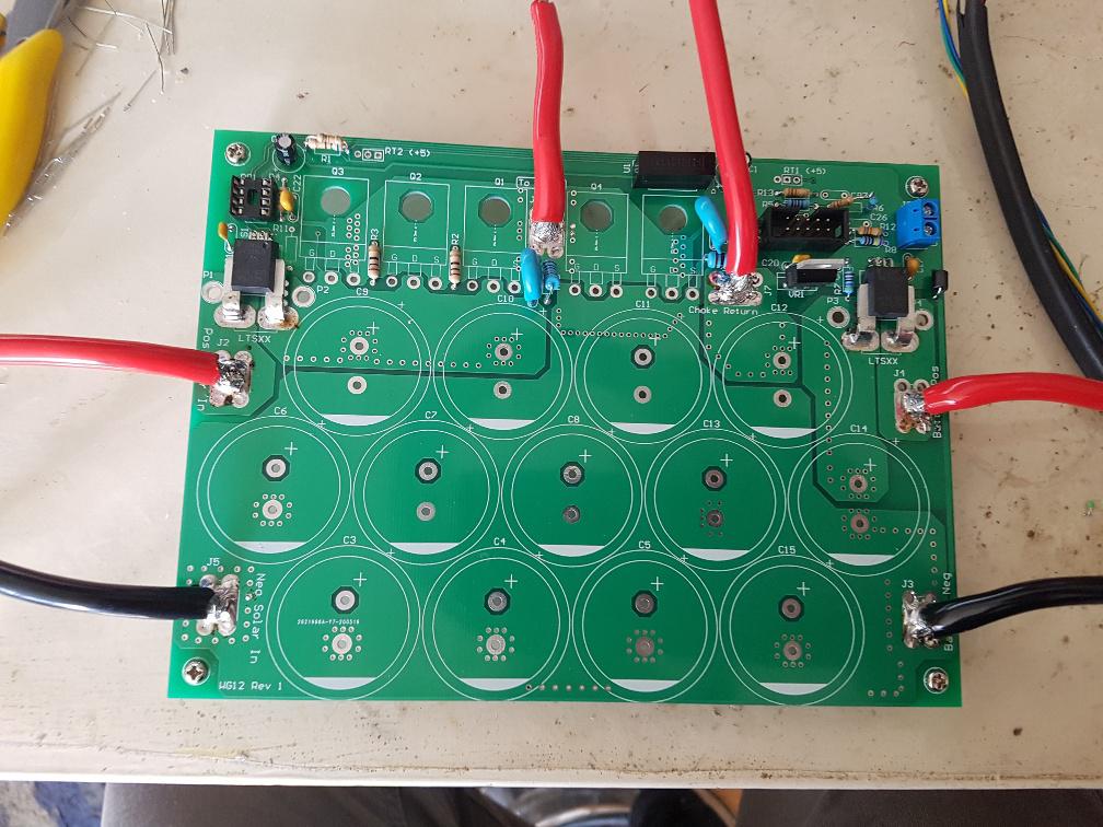 MOSFET and diode fitting detail (I only soldered the Gate pins to permit easy alignment): 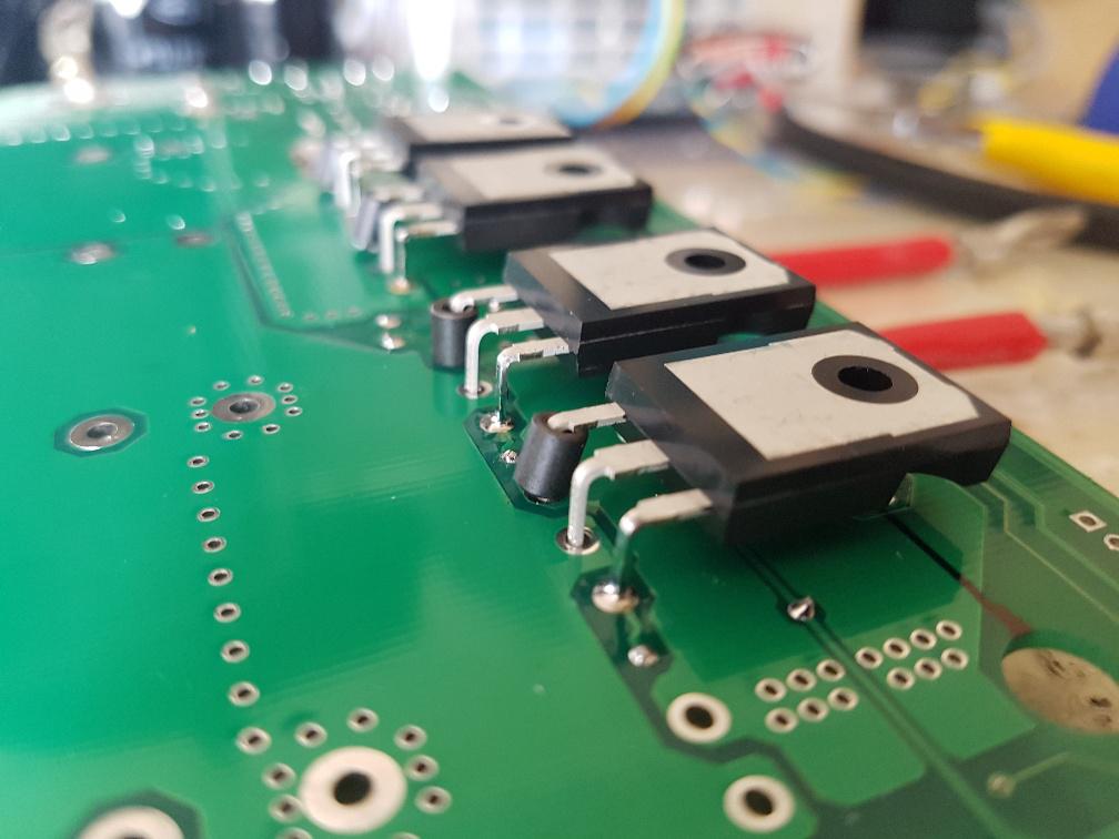 wronger than a phone book full of wrong phone numbers |
||||
| poida Guru Joined: 02/02/2017 Location: AustraliaPosts: 1420 |
Adventures with a heatsink. I wanted to get a feel for the required size of a heatsink for this project. This is the test heatsink, the same as the one I use for all the powerboard testing, as well as the now 3 week old mppt controller connected to the East solar array. It's about 130 x 145 x 40mm _resized.jpg) I have 2 IGBT transistors driven by a opamp closed loop control delivering 5.1 Amps at 20 Volts. Nearly all of this is dissipated by the IGBTs. 2.7W is sucked up by the current sense resistors. So it's about 100 W I applied 100W and recorded heatsink temperature. 100W was used since this is about 5% of 2kW and corresponds quite well with the powerboard's efficiency. Also, the IGBTs can only handle about 62W at 100C so I was skating on thin ice during these tests... Horizontal scale is minutes. Blue is what happens with no fan, and at the peak I just remove power. We can see how fast temp rises and how slow it drops with no air flow. If I did not stop the power at 64C, it would have got to at least 100C and probably much more. Red is with a large PC fan at 12V blowing air through the fins. A rapid rise to 32C and then the logarithmic curve shape as it approaches max temp. At the peak of this curve I remove power to see how fast the heatsink cools. It appears the heatsink with fan will never get hotter than about 38C 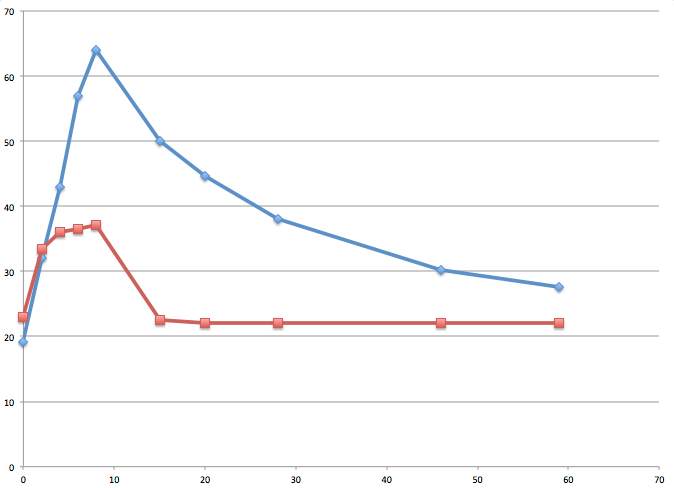 Here is a test where there is no fan until it reaches 67C and I start the fan but this time keep power applied. We see the rapid rise in temp with no fan, then the classic logarithmic response as the temp drops to it's eventual equilibrium. Which is again about 38C 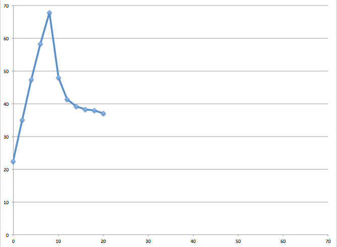 This particular fan is a bit noisy with 12V, it runs down to 6V. Let's see equilibrium heat sink temperatures for different fan voltages (or speeds) 6V 43C 7.5V 42C 9V 40C 12V 38C So you can get nearly all the cooling you will ever get with much less noise and air flow. Since we have complete control over the mppt controller due to it being software controlled, we have the option to have a fan switch on at a defined temperature and have it switch off at some other, lower temperature. As well as having a upper limit that when exceeded the controller switches off and requires a reboot. Maybe we would find it more useful if we had the output current reduced as the heatsink temperature rises, to finally reduce it to nearly zero output at a max temp. We could have for instance no output reduction for temps less than 40C. Then reduce current progressively from 40C to 75C At 75C, output current would be limited to 5 Amps. These are just random values for illustration. I think I will add this to the firmware, and have it enabled by the user when needed. Some people will have situations where the mppt controller is exposed to high power for short periods of time and most run time is with low power levels. Other people will have the controller running at max power all day. Heat sink size, using a fan or not and temperature throttled output current will give us good choices when designing the controller. wronger than a phone book full of wrong phone numbers |
||||