
|

|
Forum Index : Electronics : 6Kw Ozinverter build
| Author | Message | ||||
oztules Guru Joined: 26/07/2007 Location: AustraliaPosts: 1686 |
The index point on the plug is in the center. When you make the plug, lay out the plug /s on the bench, so that the location/index protrusion is in the same orientation for both.... not facing each other. If it is on the left for plug one, then it must be on the left for plug 2 as well. Lay the cable on them.... note orientation and clamp them. There are different gauge ribbons, make sure they are partnered to the correct plug... else crowding can occur, and shorts occur. The real test is plugging them into their respective sockets, and measuring the resistance from pin one to pin one two to two etc. This will prove that all paths are coherent, and going to the correct number pin. If any are iffy, then noise will kill the unit. Because the boards are premade, paint by number, this is the only likely culprit I can think of. I have made a lot of these, and they all start up fine, only adjustment is current and voltage, and it just works... and do not seem to fail under all normal condition folks seem to throw at them over here. I buy the cheapest drivers I can get, and hy4008 fets at Mads supplier. I have not needed to get "premium " parts to get perfect results. I have had a shaky driver... out of maybe a hundred I have used ( remember I made a lot of different prototypes getting here, and they all worked fine..... they will be in the notes there somewhere... I think I even left a pic of probably 10 boards, and there were more after that... but they all worked well. Even the bodgy 4110 fets performed well, just not as well as they could have, but all drove 2-5kw in tests. The HY4008 is just a better unit, and consistent in it's Rds values. ........oztules So I am not the best person to advise of your probable foibles, but Mad and tinker have spent a deal of time pondering all aspects Village idiot...or... just another hack out of his depth |
||||
Madness Guru Joined: 08/10/2011 Location: AustraliaPosts: 2498 |
Mark AFAIK the IR2010's are compatible, I have some here but have not had a chance to test them as yet. Double check your sockets too they can give trouble. Soldering the EG8010 is not too hard if you use SMD flux, first thing though get it exactly right with just one leg. Once that first one is correct do another on the opposite side so it is fixed in EXACTLY the right position. Once you start doing more it is near impossible to correct later. I find with the flux on all the pad you need as little solder as possible on our iron just touch the pad with the solder and the flux does the rest for you. If you get too much on solder wick takes it off. There are only 10 types of people in the world: those who understand binary, and those who don't. |
||||
renewableMark Guru Joined: 09/12/2017 Location: AustraliaPosts: 1678 |
Well I intended to look at the machine for an hour in the morning then get off and do some work, but I got caught up in it and persevered with it all day. No closer, That cable is correct, resistance shows it's right. soldered up another 8010 chip, cro tested that all looks good. something between the control board and power board must have got damaged when I used the faulty ribbon cable, but I just can't find it. Considering Mad's boards are probably not far off, I'm going to put it in the CBF basket for now. Cheers Caveman Mark Off grid eastern Melb |
||||
Madness Guru Joined: 08/10/2011 Location: AustraliaPosts: 2498 |
Mark I have been at the point of throwing the whole lot in the bin a few times. After a few hours I went back to it, I was not going to be beaten by a few MOSFETS especially when Oztules and others could get it working. I even seriously considered asking Oztules if I could get on a plane and visit him with the f'n thing. I would look at the gates of your MOSFETs with the CRO and see what you are getting there, you should see the same as you did coming out of the EG8010 and the IR2110's. Try it with the Toroid disconnected as well and see what you get on each of the smaller heatsinks. This is what you should see. 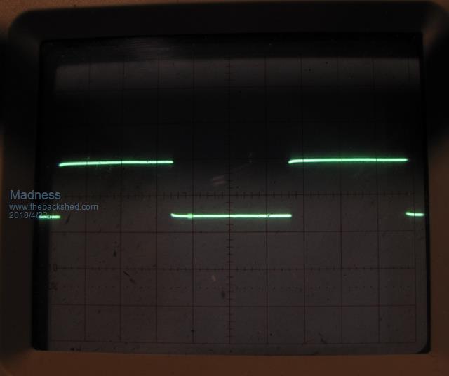 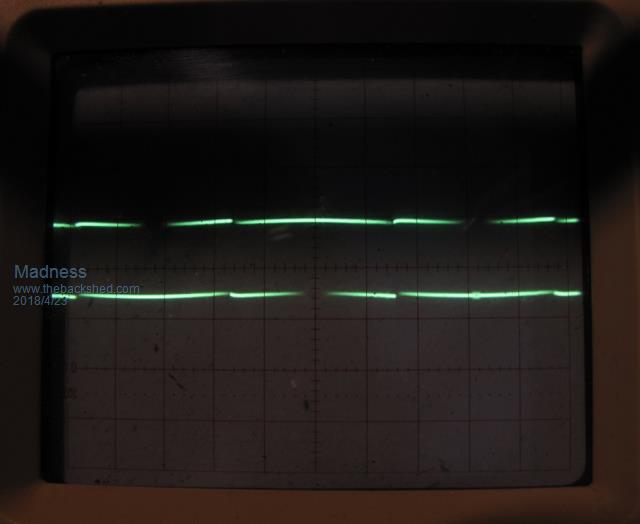 There are only 10 types of people in the world: those who understand binary, and those who don't. |
||||
renewableMark Guru Joined: 09/12/2017 Location: AustraliaPosts: 1678 |
Oh I'll still finish it mate, but just using your boards. I see little point banging my head against a wall while a better option is just around the corner. I've wasted too much time on it already. I pulled it all apart today to test each bit by themselves and really go over the power board. I'll have another crack since you went to the effort of taking and posting pics. If that fails all the bits will still get used in the Madinverter It's frustrating as I took it back to the setup it was in on p37 and it's just not working for some reason, something has failed since but just can't find it. Cheers Caveman Mark Off grid eastern Melb |
||||
| Tinker Guru Joined: 07/11/2007 Location: AustraliaPosts: 1904 |
This won't help you but gives me great satisfaction after reading about the number of faults suggested were possible with that ribbon cable  . .I'd done away with that type cable altogether, there are separate 3 pin plugs used for each bridge quarter gate drive on my board. One heck of a lot easier to check if each gate gets the correct signal...  That 10 pin plug was a carry over from the PJ conversion days, I suppose oztules kept it since he never got one wrong  . .Klaus |
||||
Madness Guru Joined: 08/10/2011 Location: AustraliaPosts: 2498 |
Mark, this is probably not what you want to hear but the boards I am doing will work just the same as those you have now should, at least with up to 16 MOSFETs. There is something up in the ones you have and it really just needs diagnosing, I know sounds easy. You need to follow right through from the power board back into the control board. From what we went over the other day I think (may be wrong though) your control board is okay at least to the IR2110s. However, I would thoroughly check the connections between the socket and those driver chips. I have had a similar result a long time ago but I would only be guessing as to what it was. You are probably better off having a break from it for a day or 2 and try again when you have cleared your head a bit. There are only 10 types of people in the world: those who understand binary, and those who don't. |
||||
renewableMark Guru Joined: 09/12/2017 Location: AustraliaPosts: 1678 |
Yes I get what you are saying, I had the board running fine producing a nice wave, just an ass bang I lost the ribbon cable and then stuffed up the next one. Something went pop(along with the fets), but stuffed if I can find it. Considering the time wasted it makes far more economic sense to start with a fresh board. I'm not totally stubborn, if it makes sense to toss the turd and start again I'll do that. Cheers Caveman Mark Off grid eastern Melb |
||||
| Warpspeed Guru Joined: 09/08/2007 Location: AustraliaPosts: 4406 |
Klaus has this exactly right. Ribbon cables are an instrument of the Devil. If you must use a ribbon cable approach it with much fear and caution and expect to have trouble. Every time you plug and unplug one you are stressing what is probably a horrible crappy joint between the ribbon and the connector. Insulation displacement joints are supposed to force a SOLID conductor between two tapered jaws where the wire is then supposed to be immovably and permanently wedged solid. Rather like a sliding type of crimp joint. Extreme constant applied pressure produces a quite good metal to metal electrical connection. Only a complete idiot would try to use this conductor wedging technique with a readily crushable multistranded wire. Think about it. If ribbon cables used single solid conductors they would not be as flexible, but at least the insulation displacement joints might stand a faint chance of working properly. If you can get the proper professional tooling to do it, its probably just barely acceptable if the whole mess is installed inside a piece of equipment and then never disturbed. Unfortunately for our typical home brew application, its never going to be left in peace but plugged, unplugged, and mercilessly stretched and flexed time after time. If you are really stuck, use pin headers and header plugs, and solder each individual wire, then cover each soldered joint with small bore heat shrink to limit flexing right at the soldered joint. Solder the male pins to the board, they never give trouble, its the females that can sometimes cause problems after many long years in a very dirty environment, so fit the females to the cable end if possible where they are more easily replaced. I don't expect anyone here to believe any of this. End of rant. Cheers, Tony. |
||||
oztules Guru Joined: 26/07/2007 Location: AustraliaPosts: 1686 |
"Only a complete idiot would try to use this conductor wedging technique with a multistranded wire. Think about it." I have thought about it..... me and all the manufacturers in the world of computers and near every other complex device and all telephone cords... are idiots...... but I knew that already... what was I thinking. Point to point wiring like tinker does, is part of the reason he took a year and a half and a mountain of fets to get a working unit. I took a day. .......oztules Village idiot...or... just another hack out of his depth |
||||
| Warpspeed Guru Joined: 09/08/2007 Location: AustraliaPosts: 4406 |
Think really cheap to manufacture like a corporate bean counter. They are smart, cunning and very intelligent people that specialize in planned obsolescence and maximum profit. Computers, telephones and similar consumer gear are only made to last a short time, and made difficult or impossible to repair before being junked or made obsolete. So go ahead and do it any way you want, I really do not care. But there is a very big difference between mass production on an assembly line where there is specialized tooling or even complete full automation, to "Fred" squashing together a few ribbon plugs together with pliers. I am no longer going to help ANYONE with their failed inverter projects, I always just get crapped upon. Cheers, Tony. |
||||
renewableMark Guru Joined: 09/12/2017 Location: AustraliaPosts: 1678 |
Tony, that's prone to making mistakes by connecting the wrong lead to the wrong pin, but at least when you push it down you would feel some resistance hopefully indicating a good contact. You can actually pull the plastic part off the IDC plug leaving the pins neatly aligned on the board. 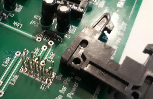 In my case, I don't think that's the problem, but I hear you, if the replacement boards weren't so cheap I would persevere and probably try that. You do seem to get confidence in a connection when you can feel it go on tight. 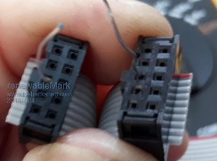 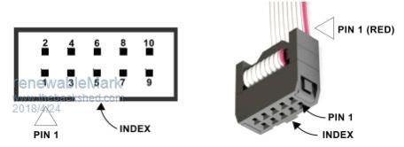 I did a resistance check on the cable by itself and pin to pin on each board, everything was fine, so that's not my issue here Cheers Caveman Mark Off grid eastern Melb |
||||
renewableMark Guru Joined: 09/12/2017 Location: AustraliaPosts: 1678 |
Good points there Tony, just for the record I appreciate your input. Cheers Caveman Mark Off grid eastern Melb |
||||
| Warpspeed Guru Joined: 09/08/2007 Location: AustraliaPosts: 4406 |
That type of connector is excellent because it has good strain relief. Most are not like that. 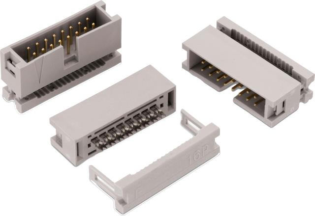 Cheers, Tony. |
||||
Madness Guru Joined: 08/10/2011 Location: AustraliaPosts: 2498 |
 There are only 10 types of people in the world: those who understand binary, and those who don't. |
||||
renewableMark Guru Joined: 09/12/2017 Location: AustraliaPosts: 1678 |
Just one out of left field here how does that crystal effect the circuit? (Control board) Cheers Caveman Mark Off grid eastern Melb |
||||
oztules Guru Joined: 26/07/2007 Location: AustraliaPosts: 1686 |
I do take your point Warp, and there is sense in it too... But life without ribbon connectors can get like this very quickly when you have data lines or a lot of interconnects  or this:  Imagine the insides of a tower, with 40 wires to the ide HD, and another 40 to the CD drive and yet another to the second disk... 120 wires drifting around the place.... and need to be fitted. The alternatives are difficult to perceive. So it seems to me to be the best bad alternative, rather than just a case of bean counting. It is simple repeatable idiot proof manufacturing..... and that makes it cheap.... I need idiot proof, so maybe thats why I am drawn to it. Don't withdraw just because we differ on opinion.... thats a good thing. Folks need your expertise more than mine, as you have a lifetime of electronic experience that I don't have. That does not mean I have to agree with every aspect of your beliefs. In this particular case, it is easy to reverse the header connection....only once. After that you get it right every time. Longevity is another matter, but in this case we just need to get it to work.... then it can be tidied up any way we want...... but to get a working example is the first priority. Once that is achieved,we get experience, and then can move on to point to point if we so chose. Because you understand what you are building ( because you designed it anyway ), it is easy to point to point, or break it down into smaller plugs and sockets as tinker has done, but as a first step, repeatable is best, and that means a paint by numbers board/s, and a blind wiring scheme ( ribbons) Prototyping can look like this, 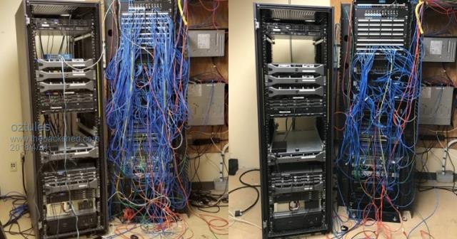 But, can you imagine manufacturing in this form? ......oztules Village idiot...or... just another hack out of his depth |
||||
oztules Guru Joined: 26/07/2007 Location: AustraliaPosts: 1686 |
"Just one out of left field here how does that crystal effect the circuit? (Control board) " The crystal is the clock for the 8010. The crystal resonates at a particular frequency, and the cpu uses this frequency as the basis for everything it does. Make sure you have a slight clearance from the board to preclude shorting the "can" to the pads under it. 1mm is plenty. ........oztules Village idiot...or... just another hack out of his depth |
||||
| Warpspeed Guru Joined: 09/08/2007 Location: AustraliaPosts: 4406 |
Oz, the largest single piece of equipment I was ever personally responsible for designing was a control desk used for theater stage automation. The one I designed was called "State 3" and just that control desk all by itself was worth over a million dollars just for the bare control desk. A whole turn key installation was several million depending on how large the project. We installed the very first one in the State Theatre in Melbourne, hence the name. And another in the Sydney Opera House, plus other complete installations in Indonesia, China, The Juilliard Theatre in New York, and Covent Garden Theater in London. That was all around 1996. After I left the company my successors designed the later "4" and "5" versions. Here is the picture of the most recent "5" version control desk. http://www.lynx.com/bytecrafts-state-v-theatre-automation-system/ My version used a couple of large card cages, and the whole beast was stuffed full with ribbon cables up to 100 conductors wide. I even successfully ran RGB video in quite long ribbon cables after some very careful impedance matching and testing. So ribbon cables do work, and are a very practical solution, but only if the ribbon connectors are very carefully assembled, and more importantly that they are not frequently moved around once installed. For the "build it on the kitchen table" type of hobbyist, there are much more suitable alternatives available, especially when the number of conductors is not that large. Designing a high end professional product is very different to designing kits for assembly by complete novices. Ribbon cables are very good for some things but are notorious for problems in less than experienced hands. Cheers, Tony. |
||||
| johnmc Senior Member Joined: 21/01/2011 Location: AustraliaPosts: 282 |
Good Day Warpspeed, I know almost nothing about electronics but you have illuminated, along with many other members, the some of the dark art of eletronics. ie "smoke catchers". Cheers john johnmc |
||||